Alli Mäkinen
School of Electrical Engineering
Thesis submitted for examination for the degree of Master of Science in Technology.
Espoo 21.11.2016
Thesis supervisors:
Prof. Raimo Kantola
Thesis advisor:
Author: Alli Mäkinen
Title: Emulation of IoT Devices
Date: 21.11.2016 Language: English Number of pages: 10+69 Department of Communications and Networking
Professorship: Internet Technologies Supervisor: Prof. Raimo Kantola Advisor: DI Jaime Jiménez
Internet of Things (IoT) connects real life objects to the Internet. In this concept, devices, such as sensors and actuators, control the physical environment generating a large amount of data that can be used in applications and services. As they are typically constrained in memory and power, lightweight implementations are needed. Moreover, the number of Internet-connected devices is continually growing and thus, the technical solutions need to be scalable too. This introduces a problem; managing such a large amount of devices as well as testing the different IoT scenarios may be cumbersome with existing physical testbeds, which require a lot of configuring and lack scalability.
This thesis proposes the design and implementation of emulated virtual devices using IoT specific protocols and data models, such as CoAP, LWM2M and IPSO objects. As device management is an important aspect of IoT, these devices are implemented to communicate with the management server through LWM2M interfaces in addition to communicating with each other. The emulated devices consist of virtual sensors and actuators represented as IPSO objects, which can be used to sense the simulated environment or control it with simple operations. Moreover, two use cases are defined and presented to create appropriate device logic. The virtualization of the devices is implemented by using Docker containers. They enable scaling to hundreds of devices, which is a key feature of the emulator. The design of the emualor follows CoAP and LWM2M specifications, which define the set of necessary functionalities and rules for the implementation. At the end of this thesis, the emulator is evaluated by comparing it to the initial design requirements along with scalability and bandwidth usage tests. Finally, future work for improving the emulator is presented.
Keywords: Internet of Things, CoAP, LWM2M, IPSO objects, emulation, virtual devices, device management
Tekijä: Alli Mäkinen
Työn nimi: IoT-laitteiden Emulaatio
Päivämäärä: 21.11.2016 Kieli: Englanti Sivumäärä: 10+69 Tietoliikenne- ja Tietoverkkotekniikan laitos
Professuuri: Internet Teknologiat Työn valvoja: Prof. Raimo Kantola Työn ohjaaja: Jaime Jiménez
Internet-verkko on nopeasti laajentunut laitteisiin, jotka voivat mitata ja ohjata ympäristöään Internet-yhteyden välityksellä muodostaen Esineiden Internetin (eng. Internet of Things, IoT). Tällaisilla laitteilla, kuten sensoreilla, on yleensä rajallisesti muistia, tehoa ja kapasiteettia tiedonkäsittelyyn. Tästä syystä onkin tärkeää, että ne ovat tekniseltä toteutukseltaan mahdollisimman kevyitä. Lisäksi IoT-laitteiden määrä kasvaa jatkuvasti, mikä tarkoittaa sitä, että teknisten toteutusten on oltava myös skaalautuvia. Valtavan laitemäärän hallinta sekä erilaisten IoT-skenaarioiden testaaminen on kuitenkin hyvin vaivalloista fyysisessä testiympäristössä, erityisesti heikon skaalautuvuuden takia.
Tämä diplomityö esittää ja toteuttaa ratkaisuksi emulaattorin, jolla voi emuloida useita virtuaalisia laitteita käyttäen IoT-protokollia ja datamalleja, kuten CoAP-ja LWM2M-protokollia sekä IPSO-objekteCoAP-ja. Koska laitehallinta on olennainen osa IoT-konseptia, virtuaaliset laitteet on toteutettu niin, että ne voivat paitsi kommunikoida keskenään, niitä voi myös hallita hallintapalvelimen kautta LWM2M-operaatioita käyttäen. Laitteet koostuvat virtuaalisista sensoreista ja kytkimistä, joita mallinnetaan IPSO-objekteilla. Niiden avulla dataa voidaan kerätä ja lähettää simuloidussa ympäristössä. Lisäksi, työssä esitellään kaksi testitapausta, joihin toteutettu laitelogiikka pohjautuu. Virtualisointi tapahtuu Docker-platformin avulla, joka mahdollistaa skaalaamisen satoihin laitteisiin. Emulaattorin toteutus pohjautuu CoAP- ja LWM2M-standardeihin, jotka määr-rittävät sallitut toiminnallisuudet ja operaatiot. Diplomityön lopussa emulaattori arvioidaan toteutuneiden suunnitteluvaatimusten sekä tehtyjen skaalautuvuustes-tien ja taajuuskaistan käyttöä tarkastelevien tesskaalautuvuustes-tien perusteella.
Preface
This thesis is conducted at NomadicLab, Oy L M Ericsson AB. This work has been the most challenging and largest academic work in my life, but then again, the most motivating and rewarding.
Firstly, I would like to thank Professor Raimo Kantola for accepting to be my supervisor for the thesis. I appreciate his comments and academic experience, which pushed me forward in the writing process.
Secondly, I would like to thank my thesis advisor, Jaime Jiménez from NomadicLab for his encouraging support, insights about the topic and useful feedback. He had always time to answer my questions and advise me. His helpful comments guided me through the whole process.
I would also like to thank all my colleagues from NomadicLab for their help and an enjoyable working environment. I also appreciate the support of my friends and family.
Contents
Abstract ii
Abstract (in Finnish) iii
Preface iv Contents v Abbreviations viii List of figures ix List of tables x 1 Introduction 1 1.1 Objectives . . . 2 1.2 Structure of thesis . . . 2 2 Background 3 2.1 Internet of Things. . . 4 2.2 The Web . . . 6 2.2.1 REST . . . 7 2.2.2 HTTP . . . 9
2.3 Communication protocols for IoT . . . 11
2.3.1 CoAP . . . 11 2.3.2 LWM2M . . . 16 2.4 Virtualization . . . 21 2.4.1 Cloud of Things . . . 21 2.4.2 Docker . . . 22 2.4.3 Greenhouse . . . 23
3.1 Requirements . . . 25
3.2 Use cases . . . 26
3.2.1 Simple IoT devices . . . 27
3.2.2 Fuel injection system . . . 30
3.2.3 Architecture . . . 32
4 Implementation 34 4.1 Software & hardware . . . 34
4.1.1 Coap-Node . . . 35
4.1.2 Leshan . . . 37
4.1.3 Hardware . . . 38
4.2 The implementation of IoT devices . . . 39
4.2.1 Object initialization . . . 40 4.2.2 Communication logic . . . 40 4.2.3 Virtualization . . . 44 5 Evaluation 48 5.1 Test environment . . . 48 5.2 Evaluation of functionalities . . . 48
5.2.1 Fulfillment of functional requirements . . . 49
5.2.2 Remaining issues . . . 50 5.3 Evaluation of scalability . . . 51 5.3.1 Reproducibility . . . 51 5.3.2 Memory usage . . . 53 5.3.3 Bandwidth usage . . . 53 5.3.4 Optimization . . . 56 6 Conclusions 59
Abbreviations
ACL Access Control List
AJAX Asynchronous JavaScript And XML API Application Programming Interface CoAP Constrained Application Protocol CoRE Constrained RESTful Environments DTLS Datagram Transport Layer Security ECM Engine Control Module
HTTP Hypertext Transfer Protocol IETF Internet Engineering Task Force IoT Internet of Things
IP Internet Protocol IPSO IP for Smart Objects
ITU International Telecommunication Union LLN Low Power and Lossy Networks
LWM2M Lightweight Machine-to-Machine M2M Machine-to-Machine
OMA Open Mobile Alliance
REST Representational State Transfer TCP Transmission Control Protocol UDP User Datagram Protocol URI Uniform Resource Identifier
WWW World Wide Web
List of figures
2.1 IoT stack. . . 6
2.2 HTTP message structure. . . 10
2.3 Example of HTTP request and response. . . 11
2.4 CoAP message format. . . 13
2.5 Examples of CoAP CON and NON messages. . . 13
2.6 The architecture of LWM2M. . . 17
2.7 The object model of LWM2M. . . 19
2.8 The architecture of full virtual machine (a) and Docker container (b). 23 3.1 Fuel injection system. [47] . . . 31
3.2 The composite IPSO object with linked objects. . . 32
3.3 Architecture of the first use case. . . 33
3.4 Architecture of the second use case. . . 33
4.1 User interface of Leshan demo server. . . 39
4.2 Networking of Docker. . . 46
5.1 Statistics about memory usage of containers from docker stat. . . 53
5.2 The current bandwidth usage of docker0 from iftop. . . 54
5.3 Traffic load from WireShark with 10 devices. . . 55
5.4 Lengths of CoAP packets measured with Wireshark. . . 56
5.5 Protocol hierarchy . . . 56
List of tables
2.1 Data elements . . . 9
2.2 CoAP response codes . . . 14
2.3 Mapping between LWM2M and CoAP operations . . . 18
3.1 Design requirements . . . 27
3.2 IPSO temperature . . . 29
3.3 IPSO objects & corresponding real sensors . . . 32
4.1 Reference values for ECM . . . 43
5.1 Fulfillment of functional requirements . . . 49
5.2 Results of scalability test 1 . . . 52
5.3 Peak bandwidth usage of docker0 interface. . . 54
While the term Internet of Things (IoT) is relatively new, the concept is not; machine-to-machine (M2M) solutions have been around for several decades enabling devices, such as sensors and actuators, to be connected to one another and communicate on closed purpose-built networks. The IoT, however, is a broader concept referring to the use of general Internet Protocol (IP) based technologies and standards, which allow devices to connect directly to the Internet. In this visionthings, that is, devices in the physical environment become smart enough to be able to communicate and process the data independently, without human intervention. Moreover, they can be remotely managed and monitored, which is another important aspect of IoT. Such connected devices typically have limited computing power, memory and battery life, which sets technical limitations to the IoT implementations; they need to be as lightweight as possible and data transmission needs to be as minimal and compact as possible. For these reasons, for example Constrained Application Protocol (CoAP) was designed. It is an application layer solution enabling devices to communicate over the Internet. It follows simple design principles, well-known from World Wide Web (WWW or web), and defines a compact message structure making it suitable for constrained environments. For device management, Lightweight Machine-to-Machine (LWM2M) protocol provides means to monitor multiple constrained devices via lightweight interfaces. It builds upon CoAP and enables interoperability between sensors or actuators and software applications by using a standard data model, LWM2M objects. Based on this model, IPSO Alliance has further defined a set of general purpose objects, which represent common types of sensors and actuators. As the number of IoT devices is expected to grow to billions, also the scalability of the technical solutions used in devices need to be considered. However, setting up physical testbeds and devices may be cumbersome and time-consuming, when it comes to testing IoT scenarios with hundreds, or even thousands of devices. For these reasons, testbeds with virtual devices could be useful. This thesis presents an emulation of IoT devices, which is appropriate for testing purposes. Emulation here refers to creating a system that behaves like real physical devices using the exact same protocol stack underneath. The virtual devices communicate using simulated
public data sources. Also in this context, an IoT device means a device, which consists of one or more sensors and actuators.
1.1
Objectives
In the beginning of this thesis, there were not sufficient IoT test devices with logic available at Ericsson and existing testbeds were rather cumbersome in terms of configuring and setting them up. The objective of this thesis is to provide general understanding of IoT and create a testbed of emulated devices using a full CoAP stack with LWM2M and IPSO objects on top of it. The emulator should simplify and ease up IoT related testing, provide devices with logic and enable scaling the amount of devices.
These devices are managed by LWM2M server, which interacts with the devices through LWM2M interfaces. IPSO objects are used to represent the common sensors and actuators and organize the data into a set of resources that can be read, written or executed. The implementation of the emulator will follow predefined design requirements and create device logic based on two use cases: emulation of several simple IoT devices and emulation of a single complex system.
1.2
Structure of thesis
This Master’s thesis consists of 6 chapters. Chapter 2 provides background infor-mation and theory relevant to the topic, describing common design principles, the most important protocols for IoT as well as the concept of virtualization. In Chapter 3, the design of the practical implementation is presented including requirements for the work and use cases. Chapter 4 deals with the actual implementation. It presents the relevant programming libraries, device logic and the tools used, such as Docker. Chapter 5 is about evaluation of the work and analyzing the scalability of the emulator based on several tests. Finally, conclusions in Chapter 6 summarize the thesis presenting the most important findings.
Internet of Things (IoT) and Machine-to-Machine (M2M) communication form the basis of the “future Internet”, where small devices with limited processing power, memory and battery, often called smart devices or smart objects, identify and control devices in the physical realm over the internet. [1] [2] The current trend of “anything that benefits from being connected will be connected” reflects well the fast development around the concept, but the realization of IoT is still in the making, both in technology and business perspective.
In general, Internet of Things can be approached with three different views: Internet-oriented (middleware), things Internet-oriented (sensors and actuators) and semantic Internet-oriented (knowledge).While the Internet-oriented approach looks for the means to integrate the heterogeneous devices and support interoperability within the applications, the starting point of the semantic view is on the services enabled by the new communication technologies. This thesis work focuses on the things oriented view, which emphasizes the active role of smart objects and particularly, the interaction and management of them. Above all, IoT is realized in the application domain, where these different approaches intersect. [3]
The IoT architecture is primarily characterized by openness, multipurpose and end-to-end interoperability contributing the use of open standards and development of new lightweight protocols, especially in the application layer [1]. These factors are shifting the M2M industry from highly fragmented vertical domains to more abstract horizontal domain, meaning that the customized, vendor-specific solutions aren’t valid anymore. It is common that different services have specific requirements and needs, which favors the development of customized solutions. However, such systems usually have inconsistent communications layers and Application Programming Interfaces (APIs), which don’t support cross-application integration. Creating a horizontal domain means sharing the common infrastructure and network elements, which brings new challenges for IoT. As vertical application requirements will still exist, support for the horizontal links requires the connectivity and information flow to be invisible to all applications. [4] [5]
This chapter provides background information required to understand the basic
concepts of IoT and virtualization. IoT heavily relies on the fundamentals of web, which are therefore explained in the beginning of this chapter. Next, the most important communication protocols for IoT, CoAP and LWM2M are introduced. Finally the concept Cloud of Things is explained along with the different virtualization tools, such as Docker and Greenhouse that are also used in the implementation.
2.1
Internet of Things
International Telecommunication Union (ITU) defines IoT as“a global infrastructure for the information society, enabling advanced services by interconnecting (physical and virtual) things based on existing and evolving interoperable information and communication technologies” [6]. It highlights both, IoT’s commercial and
tech-nological aspects. In techtech-nological point of view things, such as embedded sensor devices, communicate and share data over wired or wireless IP-based networks, the Internet. Especially, IPv6 has made it possible to feasibly connect myriads of devices by providing a large address space and features, such as IP mobility, which were not part of the original design of IPv4 [7]. In addition, IoT extends things into existing World Wide Web, adopting the well-known concepts of web and RESTful design principles. Smart objects typically have constraints on energy, bandwidth, memory and computing power, which has also motivated the development of new lightweight and compact protocols and standards, such as CoAP and LWM2M. In commercial point of view, IoT enables new kinds of services by utilizing the mass of generated data. For example, remote management and control of devices offer possibilities in maintenance business.
The decreasing costs and energy consumption of semiconductor components, in-creasing computing capabilities of sensors and actuators as well as the rise of cloud computing, and widespread adoption of Internet Protocol (IP) have driven the tech-nological development of IoT [1][9]. Moreover, this development has led to a change of traffic patterns; IoT devices exchange near real-time data in numerous, compact messages instead of bulk data. [10]. The new networks consisting of devices with limited resources are called Low Power and Lossy Networks (LLN). For example 6LowPAN [11] introduced by IETF is a low cost communication network, which makes use of small packet size and low bandwidth and hence, allow wireless connectivity in applications with limited power.
Though IoT provides a lot of possibilities, its applicability is ultimately dependent on the service requirements and the capabilities of the devices. For example,
secu-rity requirements, low battery life or low processing power of the devices may set restrictions to IoT applications. Thus, for different use cases, it may be useful to classify constrained devices based on their capabilities and identify IoT workflow to understand better the possible challenges. For example, in RFC7228, such devices have been divided into three classes; class 0 devices are the most constrained, roughly having much less than 10 KiB RAM and less than 100 KiB Flash, while class 2 devices are the least constrained having about 50 KiB RAM and 250 KiB Flash. This leaves class 1 devices in between. [2] Regardless of the device class, a simple IoT work flow of a device in general can be described with three stages [8]:
1. Sensing: smart devices collect data from the environment, for example about temperature.
2. Action: smart devices process the received data and trigger an action. 3. Feedback: smart devices provide feedback of the current status or action to
the management server or other devices.
For class 0 devices, actions, such as updating configurations or storing the security information need to be very simple and minimal, whereas more capable devices can handle larger data packets and maintain a larger database. In terms of security, it is relevant to ask, who can access the management server, does the data need to be encrypted or what kind of actions are allowed for devices to trigger. Reliability and reachability requirements also effect on the protocol choices and depend on the device capabilities.
IoT stack
The IoT stack used in this thesis is illustrated in Figure 2.1. It consists of standardized protocols, APIs, data models and the sensor application. Network connectivity between devices is provided by common physical and data link layer protocols, for example Ethernet, Wifi or 802.15.4, which is especially intended for wireless network of low-power devices. IoT utilizes the ubiquitous IP protocols, IPv4 and IPv6, for routing along with the 6LowPan, created by IETF for constrained environments. [12][13]
The scalability of web has promoted RESTful design of IoT applications suggesting the use of widely deployed Hypertext Transfer Protocol (HTTP). However, HTTP over Transmission Control Protocol (TCP) is too heavy to use with the power and memory limited devices in most cases and thus, IETF has developed a more compact
protocol CoAP, which communicates over User Datagram Protocol (UDP) by default. [13] LWM2M protocol together with IPSO object model provides a lightweight, universal interface for IoT architecture. The application software running on sensors and actuators relies on the full-stack. [12]
Figure 2.1: IoT stack.
2.2
The Web
One approach to realize IoT is to reuse the existing web technologies and standards and extend them to cover the network of constrained devices [14]. This Web of Things -approach facilitates the integration of devices with the Web considerably, since mapping traffic between the common web and emerging IoT protocols doesn’t require any complex procedures making the development easier and faster.
Web focuses on resources and content, and uses URI-based addressing scheme [15]. The resource-oriented view seems appropriate also in constrained IoT environments, where organizing and handling resources require careful planning and optimizing. Adopting the similar media types and addressing format further unifies the web and IoT. To understand better the emerging IoT technologies and their benefits, it is important to take a look first at the key concepts of web, namely RESTful design and HTTP, which are explained in the next sections in more detail.
2.2.1 REST
Fielding [16] defines Representational State Transfer (REST) as a architectural style, which provides design principles for distributed hypermedia systems. It introduces a set of constraints that aim for scalability, component independence and efficiency. In particular, the REST architecture is based on the client-server model, which separates the tasks of issuing requests (client) and providing services (server). Having two separate roles simplifies the implementation of components, but also improves portability, since components can be developed independently.
Fielding used REST to design HTTP/1.1 and URIs, making it one of the corner-stones of web. Hence, it has been a natural step to adopt the RESTful architecture for IoT as well, which has resulted in designing CoAP, a mere redesign of HTTP. Nevertheless, while the principles of REST have remained the same, CoAP has taken things further and extended the HTTP semantics. In HTTP, the endpoints have very distinct tasks: a client, for example a web browser, sends requests, while a server, for example a computer hosting a web site, provides resources accordingly. In CoAP on the other hand, the endpoints operate in both roles; for example a smart device acts as a client when registering with a resource directory, but fulfills a server role when providing sensor data [17]. Moreover, CoAP has changed the weight of the roles. HTTP server carries greater role in processing, storing and delivering the data than HTTP client, but CoAP turns the roles around. The CoAP requests are more complex in a sense that the client often needs to process data of its own resource database, whereas the request handling by CoAP server is sim-ple; resources are easily accessed from device’s own database with predefined methods. Design constraints
One of the fundamentals of the REST architecture is the stateless nature of commu-nication between the components, which removes the need for an awareness of the overall component topology. That is, the session state is kept mostly on the client. Each request must be self-descriptive, containing all information needed to under-stand the request. In addition to the improved visibility of the system, the stateless constraint increases scalability, since the server will not occupy resources for long. As a trade-off, the repetitive data increases, decreasing network performance. [16] IoT systems benefit from the stateless constraint, since it lowers memory requirements of servers, which typically are constrained and need to handle a large amount of clients [17].
REST also induces a cache constraint and a layered design, where independent, hierarchical layers restrict the knowledge of each component to a single layer. In other words, a client cannot see beyond the server it is connected to, which simplifies the overall architecture. Focus is also on a uniform interface between the components, which is optimal for common cases of web and encourages independent development of services.[16] This type of design is suitable for IoT systems; not only is it simple, but also already well-known from the use with HTTP. Hence, the integration of web services and IoT becomes easier.
Data elements
In relation to hypermedia systems, one of the most important aspects of REST is the concept of data elements (Table 2.1). They form a common base for RESTful application design and provide mutual language between the client and server, which promotes interoperability. At its core, the information is organized as set of resources, which can be retrieved, created, deleted or modified and each resource is identified, referenced and accessed through a global unique resource identifier (URI). HTTP and CoAP URIs have a common structure, which is shown below with the definitions of the components [18][19].
• Scheme creates a namespace for resources. For example “http” or “coap”. • Authorityidentifies an entity, such as the server "www.example.org" in the
current scheme. It is an IP address or a host name, with which the server can be reached, followed by an optional transport layer port number. In case of coap scheme, the default port 5683 is assumed if no port is given.
• Path identifies a resource within the scope of URI’s host and port. Path segments are separated by a slash (“/”) character. For example “/over/there” or “/rd-lookup”.
• Query contains a sequence of arguments to parameterize the resource fur-ther. The component begins with the question mark (“?”) character and the arguments are separated by the ampersand (“&”) character. For example “?ep=endpoint<=lifetime”.
• Fragmentrefers to some part of the resource, such as a section in an HTML document. It is separated by the hash (“#”) character. For example “#nose”. It is relevant for HTTP, but not for CoAP.
Components of the network exchange representations of the resources, such as HTML documents or JSON templates, in order to be able to interpret the state of the resources and perform actions on them. This introduces yet another important data element for hypertext-driven communications, a media type. Media type describes the data format of representation, that is, a set of rules for data encoding/decoding. It is sent in the “Accept” or “Content-Format/Content-Type” options field of the HTTP or CoAP header. As HTML is a typical media type for HTTP, for example JSON or TLV is typical for CoAP. The structure of the representation is specified by the representation format, which can be link or form. [21] Links are typically used in navigating among resources, while forms are used to change a resource state. For example CoAP resource discovery requests are sent in link-format with target attributes and more specific read requests are sent in form-format with GET method and a description of Content-Format. Finally, components need to define the meaning of the received requests and responses and process them by using control data. [16]
Table 2.1: Data elements
Data Element Examples
Resource Target of hypertext reference Resource identifier URL, URN
Representation HTML document, JPEG image Representation metadata Media type, Representation format Resource metadata Source link
Control data Cache-control
2.2.2 HTTP
The Hypertext Transfer Protocol (HTTP) [24] is a widely deployed stateless, appli-cation layer protocol for distributed hypermedia systems, which has been used for
web transfer since 1990. It follows a REST based request/response model building on resources, URIs, media types and methods, which make different kind of requests and functionalities possible. They include for example retrieval, search and editing of resources.
HTTP provides reliable data transfer, which is usually implemented over TCP/IP connections, but other protocols may also be used. The default TCP port is 80. HTTP communication takes place between the user agent (client) and a server, which hosts the requested resource, but different intermediates, such as proxies or gateways may be involved. HTTP connection is persistent by default meaning that only one TCP connection is established and used to carry out requests and responses. Connection can be secured by using encryption provided by TLS protocol [25] or its predecessor SSL [26].
Messaging model
There are two types of messages, requests and responses, to transfer entities, that is payload. In general they consist of start-line, message headers, empty line indicating the end of headers and possible message-body that carries entity-body. The headers in turn consist of general-header, request-header, response-header and entity-header fields. The message structure is shown in Figure 2.2. General header fields are relevant for both requests and responses. For example “Connection” field is used to signal the closing of TCP connection, which by default would otherwise remain open. Entity header fields, such as “Content-Type” provide information about the present entity-body. [24]
Figure 2.2: HTTP message structure.
As a client sends a request to the server, the message always includes the method to be applied on the target resource, the identification of the target resource (URI) and the protocol version within the start-line called a Request-Line. In addition, a request message may contain header fields, which provide additional information
about the request or client. For example, “Host” and “Accept” fields can be used to specify the target host and acceptable data format. Server responds with a message, which starts with a Status-Line containing the protocol version, status code and its textual presentation. Also the response message may have header fields that provide additional information about the server or the requested resource, such as ’Location” to redirect the request to another location than the one indicated in the request-URI. An example of HTTP request and response is shown in Figure 2.3. [24]
Figure 2.3: Example of HTTP request and response.
2.3
Communication protocols for IoT
IoT devices may communicate over the web using for example HTTP, but the constraint environment sets limitations. That is why CoAP was developed. It is basically a redesign of HTTP, but in a more appropriate form for constrained devices. CoAP uses lighter transfer mechanisms and has a shrinked header with less options. It also provides M2M-specific features, such as resource observation, which is relevant in IoT scenarios, where devices need to have up-to-date knowledge on the latest value of a specific resource. In this thesis CoAP is used on the emulation of IoT devices, LWM2M protocol on top of it. LWM2M provides a management and communication interface and a data model for smart objects. Its several APIs are used to define for example device, location, connectivity and server information. In addition, IPSO Alliance has defined a model for a set of smart objects, which can be used to represent the actual sensors and actuators in a device.
2.3.1 CoAP
The Constrained Application Protocol (CoAP), defined in [19], is a lightweight REST-ful web transfer protocol designed for constrained devices and networks, especially M2M applications. CoAP provides the basic concepts of web, such as URIs and
Internet media types, while defines specialized features for M2M, for example low overhead, multicast support and built-in resource discovery.
CoAP utilizes a request/response model between application endpoints like HTTP, but as a distinction CoAP messages are exchanged asynchronously between the endpoints over UDP by default. HTTP is a synchronous protocol in a sense that client issuing a request waits for the corresponding response, before continuing execution of other tasks. CoAP on the other hand can handle multiple simultaneous requests independently, thus performing more efficiently. In web though, the use of AJAX, a set of web development techniques, has enabled asynchronous HTTP requests [20].
UDP provides more lightweight data transfer than for example connection oriented TCP having no built-in reliability mechanism. TCP provides reliability and handles ordering of messages and tracking connections, which makes it more heavyweight. Nevertheless, recently there has been work in progress about using CoAP over TCP [27] in environments, where for example UDP based protocols may not be well received. Also in less constrained environments with only a limited amount of devices, TCP connections can easily be handled despite the possible decrease of efficiency. In fact, in the near future, TCP may be as relevant solution as UDP. In addition to the current, mandatory UDP binding, CoAP supports SMS option as well. [19] [23] CoAP also provides few security modes: no security, key-based (PreSharedKey & RawPublicKey) and certificate-based security. In a secure mode, Datagram Transport Layer Security (DTLS) [28] over UDP is used to secure the end-to-end communication channel. [19] [23]
Messaging model
CoAP requests and responses are carried in binary format messages (Figure 2.4). CoAP message format starts with a compact, fixed-size 4-byte header, which consists of CoAP version number (2-bit), message type indicator (2-bit), token length (4-bit), message code (8-bit) and message ID (16-bit). The header is followed by a variable-length token value, which is used to match requests to responses, and further by optional sequence of options and payload marker indicating the end of options and a start of payload that takes up the rest of the datagram. [19]
There are four types of CoAP messages: Confirmable (CON), Non-Confimable (NON), Acknowledgement (ACK) and Reset (RST). Reliability is provided by marking a message as Confirmable. CON messages are retransmitted at exponentially increasing
Figure 2.4: CoAP message format.
time intervals (back-off) until the recipient responds with acknowledgement message with the same message ID (for duplicate detection) or timeout is reached. The payload of the response is typically piggypacked in ACK message, but ACK may be empty if response is not immediately available. In this case, a separate response is sent later. If recipient cannot process CON message, it sends Reset message instead of ACK. On the contrary, a message that doesn’t require reliability is marked as Non-Confirmable. NON message is sent with a message ID, but not acknowledged. Instead, the response is sent in a new NON message. Example of Client/Server communication is shown in Figure 2.5. [19]
Methods and response codes
CoAP requests sent by the client and responses sent by the server are carried in CoAP messages, which include either a Method Code or a Response Code, respectively. CoAP makes use of GET, PUT, POST, and DELETE methods in a similar manner to HTTP. The GET method retrieves a representation for the information that currently corresponds to the request URI. The POST method requests that the representation enclosed in the request is processed. Depending on the target resource, POST request usually results in a new resource being created or the target resource being updated. The PUT method requests that the resource in question is updated or created with the enclosed representation. The representation data format is specified by the media type and the possible content coding. The DELETE method requests that the resource identified by the request URI is deleted. [19]
Also most of the Response Codes resemble the Status Codes of HTTP with few exceptions. The numbering is slightly modified though, for example HTTP 404 “Not Found” is written as 4.04 in CoAP. [24] [19] CoAP supports three classes of response codes defined in Table 2.2.
Table 2.2: CoAP response codes
Code Description
2.xx Success This class indicates that the request was successfully received, understood and accepted.
4.xx Client Error This class is intended for cases in which the client seems to have erred.
5.xx Server Error This class indicates to cases in which the server is aware that it has erred or is incapable of performing the request
Resource discovery
CoAP uses the "coap" and "coaps" URI schemes for identifying CoAP resources and providing means of locating the resource. One important feature of CoAP is the resource discovery, which provides information of all public resources offered by endpoints. This is particularly useful in M2M environments, where devices need to communicate with each other without human-intervention. For this purpose CoAP endpoints support the Constrained RESTful Environments (CoRE) Link Format of discoverable resources, described in [29]. The resource discovery provided by HTTP is generally called "Web Discovery", while description of relations between resources
is called "Web Linking". CoRE Link Format extends the “Web Linking” with specific M2M attributes including for example resource type “rt” attribute and interface description “if” attribute. The former one is a application specific description of a resource, for example “outdoor-temperature” or “kitchen-light”. The latter one describes the interface used to interact with the resource. It may be an URI, URN or a name, for example “sensor”.
CoAP can employ an entity called Resource Directory (RD) [30], which hosts the description of resources and a well-known resource path as a default entry point for the RD and allows lookups on resources. Performing a GET request to the well-known interface returns all available links in CoRE Link Format. The structure of a CoAP URI for resource discovery is:
coap://example.com:5683/.well-known/core
In addition, this interface supports filtering on link format attributes using query strings. For example a request GET /.well-known/core?rt=outdoor-temperature would return links that match that particular resource type. Nevertheless, server is not required to support filtering. Resource discovery can be performed either with unicast (one-to-one) or multicast (one-to-many) transmission.
Observation
The state of a resource may change over time, which can be undesirable for a client that is interested in the current representation of the resource. This has motivated the development of mechanism for a CoAP client to observe a resource on CoAP server [31]. According to the specification, the client can request that a representation of a resource is updated by the server periodically until client is no more interested in it.
The minimum and maximum time between the coming updates, notifications, are configurable and choosing the values is an important design matter in IoT applications. For example, for monitoring of public waste management system, one notification per hour may be enough [32], while monitoring presence in a room should be frequent, if the change in state is supposed to trigger an immediate action. The time interval has a significant effect on traffic load in the network.
This observer design pattern consists of two components called subject, which is a resource in the CoAP namespace, and observer, which is a CoAP client interested in the current representation of the resource. Observer registers its interest by sending an extended GET request to the server. When the state of resource changes,
server sends notification, that is, an additional CoAP response with the updated representation of the resource to the clients in the list of observers.
2.3.2 LWM2M
LWM2M is a an open industry standard, which provides a compact communica-tion interface and a data model enabling remote device management and service enablement of embedded IoT devices and resources [12]. It defines APIs for example for security, connectivity monitoring, firmware upgrade and software management. Open Mobile Alliance (OMA) designed the application layer protocol especially for constrained environments; it utilizes CoAP as an underlaying communication protocol and simple object model for organizing data. Moreover, the RESTful design of LWM2M is appealing to software developers, which makes LWM2M a potential solution for emerging IoT systems [23].
The architecture of LWM2M consists of three components: LWM2M client, LWM2M server and LWM2M bootstrap server. In essence, LWM2M client is a client soft-ware running on a M2M/IoT device, and LWM2M server is a server softsoft-ware on a M2M/IoT management and service platform. [23] Typically, the LWM2M server is located in data center and hosted by for example M2M Service Provider or Network Service Provider [12]. It is important to acknowledge that both, LWM2M client and server have the roles of CoAP client and server. The LWM2M architecture without bootstrap server is shown in Figure 2.6.
Interfaces
The communication mechanism between the components relies on four logical inter-faces: 1) Bootstrap, 2) Registration, 3) Device management & Service Enablement and 4) Information Reporting. Table 2.3 shows the mapping between all the LWM2M operations and CoAP operations and the direction of communication. Uplink means direction from the LWM2M client to the LWM2M server, while Downlink refers to direction from the LWM2M server to the LWM2M client. CoAP requests are always issued by the CoAP client, whereas responses come from the CoAP server.
Bootstrap Interface is used to enable the connection between LWM2M client and LWM2M server(s). The provisioned information between the components can be categorized into two types: LWM2M Server Bootstrap Information and LWM2M Bootstrap Server Bootstrap Information. Bootstrapping may be performed in four different modes: Factory Bootstrap, Bootstrap from Smartcard, Client Initiated or
Figure 2.6: The architecture of LWM2M.
Server Initiated Bootstrap. [33]
Registration Interface is used by the LWM2M client to register with LWM2M server(s), maintain registration and deregister from LWM2M server. During registration, the client sends “Register” operation, which provides the server the information required to contact the client and maintain the session. For example, each client must provide a unique client name, which is stored by the server. Also the list of client supported objects and existing object instances is forwarded. After registration, the client performs either periodically or on request, an “Update” operation to update its registration information. Finally when client wants to discontinue to use the services of LWM2M server, “Deregister” operation is triggered. [33]
Device management and service enablement Interface is used by the LWM2M server to access and act upon LWM2M client object instances and resources. The pos-sible operations include “Create”, “Read”, “Write”, “Execute”, “Delete”, “Write Attributes” and “Discover”. These operations allow the server to perform several actions on the resources, such as create, retrieve, update or configure resources. [33] Information Reporting Interface is used by the LWM2M server to observe changes on a resource of LWM2M client and receive notifications of new values. This is im-plemented by sending “Observe” request to the LWM2M client, after which LWM2M
client performs “Notify” operation to inform the server of the new resource values. Observation ends, when server sends “Cancel Observation” request. [33]
Table 2.3: Mapping between LWM2M and CoAP operations
LWM2M Operation CoAP Operation Direction
Request Bootstrap req: POST /bs?ep=ClientName rsp: 2.04 Changed
Uplink
Register req POST /rd?ep=ClientName<=8600&lwm2m=1&b=u rsp: 2.01 Created
Uplink
Update req: PUT /rd/AkTr0mE9v6?lt=12000&b=u rsp: 2.04 Changed
Uplink
Deregister req: DELETE /rd/AkTr0mE9v6 rsp: 2.02 Deleted
Uplink
Read req: GET /3303/0/5700
rsp: 2.05 Content
Downlink
Discover req: GET /3303/0/5700
Accept: application/link-format rsp: 2.05 Content
Downlink
Write req: PUT /3303/0/5700 rsp: 2.04 Changed
Downlink
Write Attributes req: PUT /1/0/0?pmin=10&pmax=60<=12000 rsp: 2.04 Changed
Downlink
Execute req: POST /3/0/1 rsp: 2.04 Changed
Downlink
Create Req: POST /3303/1 rsp: 2.01 Created
Downlink
Delete Req: DELETE /3303/0/5700 rsp: 2.02 Deleted
Downlink
Observation req: GET /3303/0/5700 Observe: 0 rsp 2.05 Observe: 1
Downlink
Cancel Observation Reset message
req: GET /3303/0/5700 Observe: 1 rsp: 2.05 Content
Downlink
Notify rsp: 2.04 Changed Observe: 2 rsp: 2.04 Changed Observe: 3 ...
Object model
LWM2M introduces a simple object model, where available information on LWM2M client is constructed as resources, and resources are organized logically into objects. Moreover, objects or resources may have multiple instances. The structure is illus-trated in Figure 2.7. Each object and resources within are addressed using URIs, which consist of unique identifiers, for example:
• “3/0/1”: identifies the “model number” resource of the "device" object • “3/0”: identifies the whole “device” object instance
Objects and resources must support at least one operation (read/write/execute/cre-ate/delete). In addition, LWM2M provides an access control mechanism per object instance allowing different servers to have different access rights upon objects and resources. This is realized by using Access Control Lists (ACLs) on access control object identifiers. [33]
Figure 2.7: The object model of LWM2M.
LWM2M defines an initial set of management objects, which are defined below [34]: • Security: handles the security data between the LWM2M server and the client.
One object instance should contain information about the bootstrap server. • Server: provides the data and functions related to the management server. • Access Control: defines the access rights of the LWM2M server. Access
control object instances contain ACLs that determine the allowed operations on a given object instance.
• Device: LWM2M server can query the device specific information via this object. It also provides device reboot and factory reset operations.
• Firmware: defines resources, which are needed for firmware updates. It enables for example installation of firmware packages.
• Location: provides information about the current location of the device, such as latitude and longitude.
• Connectivity monitoring: defines resources, such as "Link Quality" and "Router IP Address", which assist in monitoring the status of a network
con-nection.
• Connection statistics: provides statistical information about an existing network connection, for example about transmitted or received data.
IPSO Objects
IPSO Alliance has defined a set of general purpose smart objects, which represent common sensors and actuators. They ensure high level interoperability on the application layer by exposing a universal interface for devices and servers without the need to change the underlaying application logic. This object model is designed to operate on top of any RESTful protocols, and is based on OMA LWM2M specification. [35] [36] The object model consists of four parts described below.
Object representation follows OMA LWM2M object model, where objects and resources are structured into URI path components: Object Type ID/ Object Instance ID/ Resource Type ID. Object Type ID specifies a measurement point, for example a temperature sensor, whereas Object Instance ID represents a single instance of an measurement point. Object may have several resources, that is, properties such as current temperature value, which have their own Resource Type ID. For example 3304/0/5601 represents a humidity sensor (ID 3304) and its maximum measured value (ID 5601). [35]
Data types that the resources can be defined to be include string, integer, float, boolean, opaque, time and objlnk, which are defined in OMA LWM2M specification. [35]
Operationssupported by IPSO Objects also origin from OMA LWM2M specification. They include Read, Write, Execute, Create, Delete, Set and Discover depending on the target, which can be object, instance, resource or attribute. [35]
Format, Opaque, TLV, JSON and CBOR. In terms of media types for example text/plain, application/cbor, application/json, application/tlv and application/link-format are supported. [35]
2.4
Virtualization
This section discusses virtualization in terms of utilizing the concept in real IoT scenarios and utilizing it in the implementation part of this thesis. As the data generated by IoT devices increses, storing and processing it locally becomes difficult in real life scenarios. Cloud computing provides means to lighten the processing load of constrained devices. For implementing the testbed of virtual devices in this thesis, tools that enable building the whole virtual environment are needed. For example Docker is such a tool that can be used to create appropriate runtime environment for the applications. First, the concept of Cloud of Things, which combines IoT and cloud computing, is introduced. Next, tools called Docker and Greenhouse are presented in more detail.
2.4.1 Cloud of Things
Ericsson estimated in 2016 that the number of connected devices in total is expected to be around 28 billion by 2021, of which close to 16 billion will be related to IoT [39]. Thus, it is clear that the amount of data IoT generates is going to be vast and storing it locally is not possible anymore. Moreover, the data needs to be processed to a more suitable form for services, which can’t be managed in constrained IoT devices. This makes the importance of cloud computing evident. Aaza et al. (2014) refers to integrating IoT with cloud computing as Cloud of Things. [37]
Cloud computing provides virtual pool of computing resources and data to devices over the Internet. It is a dynamic environment that manages and allocates resources automatically and process data into more relevant form for different services. [38] User only needs to have a working Internet-connection to be able to utilize such services without any concern about the maintenance. Cloud computing presents different types of services, such as Software as a Service (SaaS) and Platform as a Service (PaaS). SaaS provides the user an access to an application on pay-as-you-go basis, whereas PaaS refers to renting a platform, which contains all the required resources needed to build applications. [37]
also has several issues related to for example protocol support, energy consumption and security. IoT may utilize different protocols, such as ZigBee or 6LowPan, depending on the environment and sensors used. Interoperability would require support for these protocols on a gateway device. Therefore, one of the suggested solutions is mapping the standardized protocols on a gateway. [37] In relation to energy issues, the operations of sensors and actuators as well as the connectivity with the cloud may consume a lot of energy, which becomes a problem, when billions of devices are connected to the network. For example new compression techniques and more efficient encoding/decoding methods improve energy efficiency as well as optimizing the use of resources on the cloud side. [37] Moving the IoT applications towards the cloud also brings security concerns due to for example lacking knowledge of the real location of data and trust in service providers. [38] These are the issues that still need to be addressed and solved before fully utilizinbg the Cloud of Things concept.
2.4.2 Docker
As the implementation of emulated devices is based on having only virtual components, a tool called Docker is utilized. It is an open platform, which enables distributed applications to run seamlessly regardless of the environment. Docker containers package the application with all the necessary runtime dependencies, system tools and libraries, and isolate it from other applications and the underlying infrastructure. That is, they guarantee that the applications run always in the same way. Containers are compatible with all major distributions of Linux and Microsoft Windows and operate on top of any infrastructure; any computer or cloud will do. [40] With Docker, we can create a separate container for each of the emulated devices. This way, each device will have their own system resources and a unique IP address.
In the core of the technology is the Docker Engine, that controls containers and images. In essence, image is a layered filesystem, which shares common files, and container is an instance of an image. Containers running on a single host machine share the kernel of the operating system and hence, use less memory (RAM) and start instantly. [41] Docker improves portability and scalability. Applications can be deployed fast, since the environmental and infrastructural constraints can be circumvented easily. In addition, Docker enables running several containers without consuming much space and memory of the host machine. [40]
Docker versus full virtual machine
Full virtual machine, or system VM, provides a complete system environment includ-ing the quest operatinclud-ing system along with the application and required binaries and libraries. It has its own set of system resources allocated and does minimal sharing. VM provides quest OS an access to virtualized hardware resources. While the system isolation is more thorough, full VM is much heavier than Docker. [42]
In contrast to VM, Docker containers share the kernel of the host OS and run as isolated processes in user space. Containers running the same OS image share the size of the image. Thus, docker can easily run hundreds or even thousands of containers simultaneously. The architectural difference is visualized in Figure 2.8. All in all, VM provides full isolation and guaranteed resources, while Docker provides less isolation, but lightweight platform for multiple simultaneous containers. [40]
(a) (b)
Figure 2.8: The architecture of full virtual machine (a) and Docker con-tainer (b).
2.4.3 Greenhouse
Greenhouse is a DevOps tool suite by Ericsson (currently internal use only), which provides custom functionality to existing platforms, for example configuration man-agement or automatic proxy handling. It is based on service choreography rather than service orchestration [44]. Service choreography is a decentralized form of service composition, which has a global perspective. It tracks message sequences between multiple endpoints instead of actions by a single party. Service orchestration
is a centralized model, where a single business process, orchestrator, control the interaction of multiple services. [43]
The Greenhouse architecture consists of four components: Bitverse, Facehugger, Farmer and Web-UI. Greenhouse creates decentralized peer-to-peer (p2p) network of containers, to which it injects its management processes to manage the application. The architectural components are discussed briefly below [44].
• Facehugger: a tool to inject Greenhouse functionality to existing docker container. User chooses, which tools are activated.
• Farmer: a gateway to support the different underlying platforms, such as Docker or Apcera. It consists of a daemon process (Farmerdaemon) and an executable (Farmer CLI).
• Bitwerse: a Distributed Hash Table (DHT) which handles state synchroniza-tion and messaging between distributed components. It implements two kinds of nodes: supernodes, which manage routing in bitverse network and edgenodes, which are integrated in clients and support sending messages to other clients. • Web-UI: a web-based user interface that visualizes the system.
As mentioned above, Greenhouse functionality is based on a set of tools, which can be independently activated. In this thesis work, the relevant tools are Jekyll and Tesla. Jekyll coordinates the running containers by starting and stopping them as appropriate. Tesla is used to find dependent containers in the network, connecting for example, the LWM2M clients to the LWM2M server. This is done by determining the polarity of the component: positive polarity (+) means the container is a “producer” (eg. LWM2M server) and a negative polarity (-) means the container is a “consumer” (eg. LWM2M client). Tesla automatically resolves mapping between virtual and
physical ports and determines the IP address of the host machine, making it possible to run several identical containers on the same machine.
In this thesis, an IoT device consists of one or more virtual sensors, which harvest information from the simulated environment and convey it to the management server or virtual actuators, which act like a switch being able to change the status of the device and inform the management server about it. The emulation of such devices is implemented by creating a LWM2M client software, which utilizes random data and is able to perform several basic functions through LWM2M and IPSO objects. As examples of IoT use cases, we present several simple IoT devices communicating with the management server and with each other, and a single complex system communicating with the management server.
This chapter defines the design requirements for the LWM2M clients and presents the use cases in more detail. Also the chosen IPSO objects and the architecture of the use cases are discussed.
3.1
Requirements
One of the goals of this thesis is to implement several virtual devices, LWM2M clients, which can be managed by the LWM2M server and communicate directly with each other. There is a set of client specific requirements stemmed from the LWM2M specification, but also more general scalability requirements, all of which are listed in Table 3.1 with the indication of their importance in the implementation.
In general, the most important client specific functionalities are LWM2M client’s ability to register, read, write and execute resources of single-instance objects and deregister. Single-instance object refers to an object, which is allowed to have only one instance, while multi-instance object may have several different instances. The division between single-instance and multi-instance objects is made here, since they support different data formats; single-instance objects may be dealt with for example plain text, whereas multi-instance objects must support JSON and/or TLV format. As important as communication between LWM2M server and client is, also the direct communication between LWM2M clients is important in real IoT scenarios, where devices need to be able to communicate without human intervention.
In addition, there are several requirements regarding scalability. For example repro-ducibility, memory usage and bandwidth usage of the devices (docker containers) are important factors in the implementation. LWM2M server should be able to handle hundreds of simultaneous devices, which send periodically data to the network. As the number of connected devices increases, the bandwidth and memory usage may become a problem, if not taken into account in the implementation.
3.2
Use cases
The implementation part involves two use cases: emulation of several simple devices and emulation of one complex system consisting of multiple sensors and actuators. In the former case, four different virtual devices, a weather observer, a radiator, a presence detector and a light controller are connected to a network. A weather observer and a radiator together control a room temperature, while a presence detector and a light controller manage the status of the lights depending on the occupancy of the room. This use case is chosen, because it demonstrates simple IoT scenarios showing the basic use of common sensors and actuators. Moreover, it is an appropriate and realistic use case for scalability testing. For example buildings usually have several lights and radiators that could be controlled by IoT.
The second use case presents a complex system, engine fuel injection system of a car, which consists of multiple virtual sensors and actuators. The heart of every modern car is a engine control module (ECM), a microcontroller, which controls several engine operations for the engine to run efficiently and economically. Its main tasks include control of fuel injection and fuel ignition. The focus of this use case is on the fuel injection. ECM receives information from different sensors, such as throttle position, cramshaft speed, coolant temperature and mass air flow sensors in real time and adjusts the time fuel injectors are open. Fuel injectors are basically ON/OFF switches, which open and close the injector valves accordingly. ECM also needs to check that the fuel is pumped at the correct pressure and make corrections if necessary. This use case shows, how a complex systems may be modeled and managed in IoT.
Table 3.1: Design requirements
Functionality Description Importance
Registration/ Deregistration
LWM2M client is able to register/deregister to/from the management server.
High
Resource initialization LWM2M client is able to initialize objects and resources.
High
Single-instance support: read/write/execute
LWM2M client is able to read, write and execute resources of single-instance objects.
High
Multi-instance support: read/write/execute
LWM2M client is able to read, write and execute resources of multi-instance object and read the whole instance.
Medium
Create/Delete LWM2M client is able to create and delete object instances.
Medium
Observe/Notify LWM2M client supports observe/notify concept.
High
JSON/TLV format LWM2M client supports JSON and/or TLV format required for handling multi-instance objects.
High
Device-to-Device communication
LWM2M clients are able to communicate di-rectly to each other.
High
Reproducibility LWM2M server should be able to handle hundreds of simultaneous clients.
High
Memory Usage LWM2M client should consume as little mem-ory as possible
High
Bandwidth Usage LWM2M client should generate small amounts of traffic in nearly real time instead of bulk data.
Medium
3.2.1 Simple IoT devices
This use case includes four devices: a weather observer, a radiator, a presence detector and a light controller. A weather observer simply provides temperature readings utilizing either random data or an OpenWeatherMap data source to get current
weather data from real weather stations. It has a programmable target temperature value for the room to which it compares the current temperature and if necessary, sends a control message to a radiator. A radiator switches its status to ON or OFF based on the control message. A presence detector observes occupancy of a room and sends a control message to a light controller, when its status is changed. A light controller turns the lights ON or OFF based on the control message.
For the emulation of these simple devices, IPSO temperature, humidity, light control, presence, set point and general actuator objects were chosen. They represent very common types of sensors and actuators, which enable remote data measurement (e.g. temperature sensor) and control (e.g. light control actuator) and thus, are appropriate targets for emulation purposes. A weather observer consists of a temperature and humidity sensors, a radiator consists of a general ON/OFF and a set point actuators, a presence detector comprises of a presence sensor and a light controller comprises of a light control actuator.
Temperature and humidity sensors can report current temperature/humidity values, minimum/maximum measured values and the range used, while the light control actuator can control a light source, such as a LED by allowing the light to be turned ON and OFF and for example setting dimmer between 0-100% and counting the time the device has been on. A general actuator is very much similar. A presence sensor can report the current state of itself and count the number of “active” states detected. Set point actuator allows setting a specific target value. As an example, a temperature sensor and its resources are described in Table 3.2.
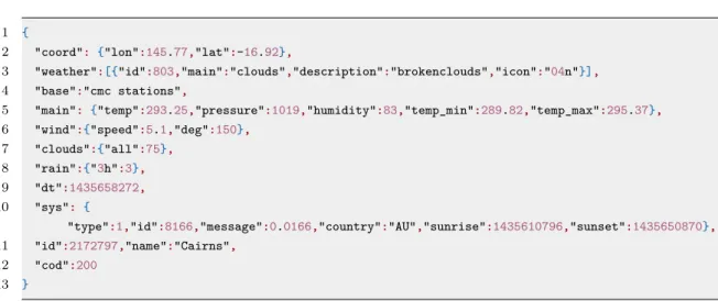
OpenWeatherMap
OpenWeatherMap [45] is an open data source, which is utilized in the weather observer. Data is collected from thousands of remote sensors of over 40 000 weather stations all around the world. User can access the current weather data of over 200 000 cities. In the implementation, the data from Helsinki weather station is used. It is provided in JSON, XML or HTML format through APIs. An example of API respond in JSON format:
1 {
2 "coord": {"lon":145.77,"lat":-16.92},
3 "weather":[{"id":803,"main":"clouds","description":"brokenclouds","icon":"04n"}], 4 "base":"cmc stations",
5 "main": {"temp":293.25,"pressure":1019,"humidity":83,"temp_min":289.82,"temp_max":295.37}, 6 "wind":{"speed":5.1,"deg":150},
7 "clouds":{"all":75}, 8 "rain":{"3h":3}, 9 "dt":1435658272, 10 "sys": {
"type":1,"id":8166,"message":0.0166,"country":"AU","sunrise":1435610796,"sunset":1435650870}, 11 "id":2172797,"name":"Cairns",
12 "cod":200
13 }
Usage of the data source requires an API key, which is acquired by registering to the service. In addition, integrating the API to the implementation requires using a small abstraction layer, for example node-openweathermap [46] can be utilized for that.
Table 3.2: IPSO temperature
Object Name ID Instances Object URN
Temperature Sensor 3303 Multiple urn:oma:lwm2m:ext:3303
Resource ID Oper. Mandatory Type Units Description
Sensor Value 5700 R Mandatory Float Defined by “Units” resource
Current measured sensor value
Min Measured Value
5601 R Optional Float Defined by “Units” resource
The minimum value measured by the sen-sor since power ON Max Measured
Value
5602 R Optional Float Defined by “Units” resource
The maximum value measured by the sen-sor since power ON Min Range
Value
5603 R Optional Float Defined by “Units” resource
The minimum value that can be measured Max Range
Value
5604 R Optional Float Defined by “Units” resource
The maximum value that can be measured Sensor Units 5701 R Optional String Measurement units definition e.g. “Cel” for celsius
Reset Min and Max Measured Values
5605 E Optional String Reset the min and max measured values to current value
3.2.2 Fuel injection system
Fuel injection system is a complex system consisting of multiple parts, which ensure the fuel is used efficiently. In essence, fuel is pumped from the fuel tank to the engine under pressure and finally to the cylinders. In modern cars the fuel injection system is electronical: the operation is controlled entirely by a microprocessor, a miniatur computer called ECM. The system also uses indirect injection, where injectors spray fuel into an inlet valve rather than directly to combustion chamber to feed cylinders. This way the fuel mixes properly with air. [47]
Different operating conditions require different fuel/air mix and different amount of fuel. In order to control these factors, ECM monitors several sensors. It compares the sensor values to the predefined factory values and based on that determines the correct amount of fuel needed. The Figure 3.1 illustrates the fuel injection system and its components. This use case models the following sensors and actuators:
• Throttle Position Sensor (TPS): signals the throttle position, which is dependent on the position of a gas pedal. As the pedal is stepped on and off, the throttle is opened and closed accordingly letting correct amount of air flow to the engine. Computer uses this information to determine the required amount of fuel. [49]
• Mass Airflow (MAF) sensor: signals the air mass entering the engine. The information is needed to calculate the correct amount of fuel needed. [50] • Engine Coolant Temperature (ECT) sensor: measures the internal
tem-perature of the engine and signals the temtem-perature changes to the ECM. The information is needed for the ECM to determine if the engine is cold, warm or overheating. [51]
• Crankshaft speed sensor: measures the rotational speed of the crankshaft. This information is also used to control fuel injection. Higher the engine speed, the more fuel is needed. [52]
• Fuel pressure sensor: measures the pressure of fuel in the rail. The pressure drop is signaled to the ECM, which restorates the pressure by controlling the pump valve. [47]
• Fuel pump valve: is an ON/OFF switch controlled by ECM. It is used to set the correct fuel pressure. [47]
• Fuel injector: is an On/OFF switch controlled by ECM. Injectors are opened and closed to feed the cylinders with a correct amount of fuel. [47]
Figure 3.1: Fuel injection system. [47]
A complex device or system can be modeled with a IPSO composite object, which of resources are links to other objects. In a constraint environment a composite object may be a lighter solution than a large nested object in a sense that it enables observation of only linked object instances instead of the full object. Thus, it saves bandwidth. [35] Here, we chose IPSO 4000 ObjectInstanceHandler, which represent a common composite object. The Table 3.3 shows the chosen linked IPSO objects and the corresponding real sensors. In reality, ECM contains both analog and digital inputs and outputs. Typically the sensors output a voltage value, which is proportional to the real measurement value. ECM digitize the data from analog sensors and calculates engine settings based on the voltage inputs. [53] The composite object with links is illustrated in Figure 3.2.
Table 3.3: IPSO objects & corresponding real sensors IPSO Object Real Sensor/Actuator IPSO 3303 Temperature ECT Sensor
IPSO 3316 Voltage Throttle Position Sensor IPSO 3316 Rate Mass Airflow Sensor IPSO 3346 Rate Crankshaft Speed Sensor IPSO 3323 Pressure Fuel Pressure Sensor IPSO 3306 Actuator Fuel Injector
IPSO 3306 Actuator Pump Valve
Figure 3.2: The composite IPSO object with linked objects.
3.2.3 Architecture
The overall architecture of the first use case consists of five components: LWM2M server and four LWM2M clients: weather observer, radiator, presence detector and light controller. The architecture is shown in Figure 3.3. All devices are connected to and managed by the LWM2M server, which maintains a registry of the available resources. In addition, a weather observer and a radiator as well as a presence detector and a light controller are communicating directly with each other.
Figure 3.3: Architecture of the first use case.
The architecture of the second use case is illustrated in Figure 3.4. The LWM2M server communicates with the fuel injection system operated by the ECM. ECM receives information from coolant temperature, throttle position, pressure, mass airflow and crankshaft speed sensors, and based on the current values sends commands to fuel pump valve to control the fuel pressure and fuel injector to control the amount of fuel injected into the cylinders.