D
epartment of
I
nformatics and
S
ystems
E
ngineering
,
Centre for Autonomous Systems
PhD THESIS
Academic Year 2009 - 2012
Jiyoung Choi
Model Checking for Decision Making
Behaviour of Heterogeneous
Multi-Agent Autonomous System
Supervisor:
Professor Antonios Tsourdos
January 2012
This thesis is submitted in partial fulfillment of the requirements for the Doctor of Philosophy
c
Cranfield University, 2012. All rights reserved. No part of this publication may be
An autonomous system has been widely applied for various civil/military re-search because of its versatile capability of understanding high-level intent and direction of a surrounding environment and targets of interest. However, as au-tonomous systems can be out of control to cause serious loss, injury, or death in the worst case, the verification of their functionalities has got increasing atten-tion. For that reason, this study is focused on the verification of a heterogeneous multi-agent autonomous system. The thesis first presents an overview of formal methods, especially focuses on model checking for autonomous systems verifica-tion. Then, six case studies are presented to verify the decision making behaviours of multi-agent system using two basic scenarios: surveillance and convoy. The initial system considered in the surveillance mission consists of a ground con-trol system and a micro aerial vehicle. Their decision-making behaviours are represented by means of Kripke model and computational tree logic is used to specify the properties of this system. For automatic verification, MCMAS (Model Checker for Multi-Agent Systems) is adopted due to its novel capability to ac-commodate the multi-agent system. After that, the initial system is extended to include a substitute micro aerial vehicle. These initial case studies are then further extended based on SEAS DTC exemplar 2 dealing with behaviours of convoy protection. This case study includes now a ground control system, an unmanned aerial vehicle, and an unmanned ground vehicle. The MCMAS suc-cessfully verifies the targeting behaviours of the team-level unmanned systems. Reversely, these verification results help retrospectively improve the design of decision-making algorithms by considering additional agents and behaviours during four steps of scenario modification. Consequently, the last scenario deals with the system composed of a ground control system, two unmanned aerial vehicles, and four unmanned ground vehicles with fault-tolerant and communi-cations relay capabilities. In conclusion, this study demonstrates the feasibility of model checking algorithms as a verification tool of a multi-agent system in an initial design stage. Moreover, this research can be an important first step of the certification of multi-agent autonomous systems for the domains of robotics, aerospace and aeronautics.
my handsome husband, and
my lovely daughter
First of all, I appreciate my supervisor, Prof Antonios Tsourdos, for his thought-ful consideration and valuable guidance all through this journey. I would like to thank Dr Peter Silson and Prof Brian White for reviewing my study and giving me precious comments about my research. I would also like to thank Dr Seunk-Keun Kim who provided valuable advice for revision of my papers and Dr Robert Alexander who offered me the related research in the inital stages of my study. Especially, I appreciate Graham Watson for giving me the motivation and ideas on my research scenario.
Abstract i Acknowledgements ii Nomenclature x 1 Introduction 1 1.1 Aim of research . . . 1 1.2 Related Work . . . 2
1.3 Contributions of the thesis . . . 5
1.4 Structure of the thesis . . . 7
2 Model Checking-Background Knowledge 8 2.1 Formal methods . . . 8
2.1.1 Formal methods and Systems Life-cycle . . . 8
2.1.2 Formal modelling . . . 11
2.1.3 Kripke modelling . . . 12
2.2 Formal specification: verifiable logic . . . 14
2.2.1 Propositional logic . . . 14
2.2.2 Modal logic . . . 15
2.2.3 Temporal logic . . . 15
2.3 Model checker . . . 16
2.3.1 Why model checking? . . . 16
2.3.2 Definition and requirement of model checker . . . 17
2.3.3 Model checking tools . . . 19
3 Surveillance Mission by a Single MAV 23
3.1 Scenario definition . . . 23
3.2 Kripke modelling of multi-agent system . . . 25
3.2.1 Kripke model for MAV . . . 25
3.2.2 Kripke model for GCS . . . 26
3.3 Modelling of properties to be verified . . . 27
3.4 Model checking with MCMAS . . . 28
3.4.1 MCMAS model . . . 28
3.4.2 Verification results . . . 31
3.4.3 Analysis and discussion . . . 31
3.5 Extended scenario definition . . . 32
3.6 Kripke modelling of extended scenario . . . 33
3.6.1 Kripke model for MAV and substitute MAV . . . 33
3.6.2 Kripke model for GCS with additional behaviour . . . 33
3.7 Property modelling of extended scenario . . . 34
3.8 Model checking of extended scenario . . . 35
3.8.1 MCMAS model . . . 35
3.8.2 Verification results . . . 35
3.8.3 Analysis and discussion . . . 35
4 Convoy Mission by Single UAV and Single UGV 37 4.1 Scenario definition . . . 37
4.2 Kripke modelling of multi-agent system . . . 38
4.2.1 Kripke model for UAV . . . 38
4.2.2 Kripke model for UGV . . . 39
4.2.3 Kripke model for GCS . . . 41
4.4 Model checking with MCMAS . . . 43
4.4.1 MCMAS model . . . 43
4.4.2 Verification result . . . 44
4.4.3 Analysis and discussion . . . 44
5 Convoy mission by a group of UAVs and UGVs 47 5.1 Scenario definition . . . 47
5.2 Kripke modelling of multi-agent system . . . 47
5.2.1 Kripke model for UAV 1 . . . 47
5.2.2 Kripke model for UAV 2 . . . 49
5.2.3 Kripke model for UGV . . . 50
5.2.4 Kripke model for GCS . . . 52
5.3 Modelling of properties to be verified . . . 52
5.4 Model checking with MCMAS . . . 53
5.4.1 MCMAS model . . . 53
5.4.2 Verification results . . . 54
5.4.3 Analysis and discussion . . . 54
6 Convoy mission by a group of UAVs and UGVs including fault problem 58 6.1 Scenario definition . . . 58
6.2 Kripke modelling of multi-agent system . . . 58
6.2.1 Kripke model for UAV 1 . . . 58
6.2.2 Kripke model for UAV 2 . . . 59
6.2.3 Kripke model for UGVs . . . 60
6.2.4 Kripke model for GCS . . . 63
6.3 Modelling of properties to be verified . . . 63
6.4 Model checking with MCMAS . . . 64
6.4.1 MCMAS model . . . 64
6.4.2 Verification result . . . 64
7 Convoy mission by UAV and UGV swarms with communications relay 69
7.1 Scenario definition . . . 69
7.2 Kripke modelling of multi-agent system . . . 69
7.2.1 Kripke model for UAV 1 . . . 69
7.2.2 Kripke model for UAV 2 . . . 72
7.2.3 Kripke model for UGVs . . . 74
7.2.4 Kripke model for GCS . . . 77
7.3 Modelling of properties to be verified . . . 78
7.4 Model checking with MCMAS . . . 79
7.4.1 MCMAS model . . . 79
7.4.2 Verification result . . . 79
7.4.3 Analysis and discussion . . . 80
8 Conclusions and Future Work 85 8.1 Summary . . . 85
8.2 Discussions . . . 87
8.3 Future Work . . . 89
2.1 The graphical representation of Kripke model . . . 13
2.2 Representations of LTL and CTL for a given transition system . . . 16
3.1 Sky view of Copehill Down . . . 24
3.2 The Stellar team in Grand Challenge . . . 24
3.3 The scenario overview of surveillance mission by a single MAV in perspective of Grand Challenge mission . . . 25
3.4 Kripke model for the MAV . . . 26
3.5 Kripke model for the GCS . . . 27
3.6 The elements of MCMAS model in Section 3.4.1 . . . 28
3.7 ISPL code used for this chapter . . . 30
3.8 Verification results . . . 31
3.9 The counterexample of formula 2 . . . 31
3.10 Kripke model for the MAV and the substitute MAV . . . 33
3.11 Kripke model for the GCS with replacement behaviour . . . 34
3.12 Verification result of modified scenario . . . 36
4.1 Convoy mission using single UAV and single UGV . . . 38
4.2 Kripke model for the UAV . . . 38
4.3 Kripke model for the UGV . . . 40
4.4 Kripke model for the GCS . . . 41
4.5 Verification Result . . . 45
4.6 Comparision of BDD information . . . 46
5.1 Extended system with a group of UAVs and UGVs . . . 48
5.3 Kripke model for UAV 2 . . . 50
5.4 Kripke model for the UGV . . . 51
5.5 Verification Result . . . 54
5.6 Counterexample of formula 9 . . . 55
5.7 BDD information of verification result . . . 57
6.1 Kripke model for UAV 2 . . . 59
6.2 Kripke model for the UGV . . . 60
6.3 Verification Result . . . 65
6.4 Counterexample of formula 8 . . . 66
6.5 Counterexample of formula 13 . . . 67
6.6 BDD information of verification result . . . 68
7.1 Convoy mission of multi-agent system using communication relay 70 7.2 Kripke model for UAV 1 . . . 70
7.3 Kripke model for UAV 2 . . . 72
7.4 Kripke model for the UGV . . . 75
7.5 Verification Result . . . 79
7.6 Counterexample of formulae 1 . . . 81
7.7 Counterexample of formulae 2 . . . 82
7.8 BDD information of verification result . . . 84
8.1 System extension of surveillance mission scenario . . . 86
8.2 System extension of convoy mission scenario . . . 86
8.3 Comparison of BDD data . . . 87
All units are in SI unless otherwise stated
Alphanumeric
L Labelling function R Accessibility relation W A set of possible worlds
Abbreviations
CTL Computational Tree Logic DTC Defence Technology Centre FSA Finite State Automata GCS Groud Control System
ISPL Interpreted Systems Programming Language LTL Linear Temporal Logic
MAV Micro Aerial Vehicle
MCMAS Model Checker for Multi-Agent Systems MoD Ministry of Defence
MSC Message Sequence Chart
OBDD Ordered Binary Decision Diagram PLTL Propositional Linear Temporal Logic PN Petri Net
RTTL Real-Time Temporal Logic
SMV Symbolic Model Verifier SPIN Simple Promela Interpreter UAV Unmanned Aeial Vehicle UGV Unmanned Ground Vehicle
Introduction
1.1 Aim of research
An autonomous system is capable of understanding higher level intent and direction. From this understanding and its perception of its environment, such a system is able to take appropriate action to bring about a desired state. It is capable of deciding a course of action, from a number of alternatives, without depending on human oversight and control, although these may still be present. Although the over-all activity of an autonomous unmanned aircraft will be predictable, individual actions may not be.
This is a definition of autonomous systems [1]. To use such autonomous systems has attracted extensive attention to many civil/military applications as Unmanned Aerial Vehicles (UAVs). They are commonly used for the tasks associated with four elements: dull, dirty, dangerous and deep[2]. Surveillance mission, a role of communication relay, or acting as a air-to air refuelling tanker can be considered asdull tasks. Dirtytasks are missions in contaminated environments by CBRN (Chemical, Biological, Radiological, or Nuclear) elements. For instance, UAVs are being applied for the reconnaissance over civilian fire locations that is dan-gerous to human because of smoke and flames. Moreover, UAVs are recently committed to the battlefield, for example, Predator in Libya, for the performance of dangerous tasks. Lastly, deep tasks are kinds of penetrating enemy territory to complete observation and attack missions. As various tasks of autonomous systems get introduced, safety concerns to the operations in a general public area have been raised because autonomous systems can be out of control enough to cause loss, injury, or death to persons or property. Safety cannot be guaranteed simply by good design because the any behaviour of system may be upset by mistakes made during its production, installation or use[52]. Furthermore, to ap-ply autonomous systems to more complex missions the structure of systems has got more complicated, which increases the possibility of malfunctions. Therefore,
aviation communities in most of the countries have focused on the regulatory authorities and certification to supervise the manufacture and operation of au-tonomous systems. Federal Aviation Administration in USA issued a Notice of Policy on Unmanned Aircraft in the National Airspace System in 2007 [3] and has focused on the development of certification standards to make unmanned aircraft system uniformly certified. SEAS DTC in UK has also been focusing on certifica-tion, especially for safety-related issues, in their research scope [4]. This study has been motivated by this demand of certification for autonomous systems. Since the research about the regulation for autonomous systems is in the initial phase, the most important part for the current certification issues is to abstract the essential properties which must be valid in autonomous systems in realistic application scenarios. For that reason, this thesis deals with several practical scenarios and aims to move forward towards the verification of heterogeneous autonomous systems.
1.2 Related Work
Beyond a single-agent autonomous system, a group of autonomous systems could be more reliable due to inherent redundancy to unexpectedness. Here, the agent means autonomous program which should select an proper action that is expected to maximise its performance measure, given the evidence provided by the per-cept sequence and whatever built-in knowledge it has[5]. In this background, a multi-agent autonomous system has been recently considered as a substitute to the single-agent autonomous system for higher mission successfulness[6]. In the reference [7], a team of UAVs were used to search an area of interest that contains regions of opportunity and potential hazard cooperatively. Kloetzer and Belta [8] developed a hierarchical framework for mission planning and control of robotic groups. Moreover, mission planning and optimization for multiple UAVs has been studied by using Linear Temporal Logic (LTL) [9, 10]. The temporal logic was used to perform motion planning for robots as well [11, 12]. For complicated systems, there have been attempts to verify the reliability of them at the design level by using a simulation in a virtual environment [13], a test with a mock-up, and formal methods. Firstly, the test with a mock-up costs a lot of money and time and does not guarantee the safety during the operation. Although the
sim-ulation costs less than the mock-up test, it is not easy to consider all the possible scenarios and situations. On the other hand, the formal methods are based on solid mathematical techniques and offer quantifiable answers to questions related with reliability of systems. Chaudemar et al. proposed a formal specification of the layered architecture of the UAV control system within the safety analysis using the Event-B method [14]. The Event-B is one of formal languages developed to specify and model the complex system with refinement mechanism [15]. In the reference [16], a formal approach to reactive system design was presented using POLIS [17]. Another formal approach, reverse engineering, was used to describe a case study involving a mission control system developed by the NASA Jet Propulsion Laboratory to command an unmanned spacecraft in [18]. Model-checking [19] is an automatic technique based on formal methods for verifying a finite state system to automatically check whether the target system satisfies the required properties or not. There are three sub-processes in model-checking: modelling, specification, and verification. The system to be verified is abstracted and translated into a language used in a model checker. The properties which we are interested in are specified by means of temporal logic. Finally, the model checker verifies the system properties and gives the result with yes or no on the system satisfying them. In [, baie08] model-checking technique is compared to a computer chess program. A model checker examines all possible systems sce-narios in a systematic manner like a computer chess program checks all possible moves. In this way, model-checking provides exhaustive verification ability that makes far more wide-reaching states verified than testing and simulation. Thus, model checkers are widely used to verify the safety-critical or high-autonomy systems. SPIN [20, 21] and SMV [22] are the most widely-used model checkers and have pros and cons respectively. SPIN was originated from automated pro-tocol validation techniques introduced by Holzmann to deal with industrial-size problems [23]. Holzmann andet al. studied about new reduction strategies for conventional reachability analysis, as used in [23], to reduce either run time or memory requirements by four to six times [24] and this study based the SPIN. Al-though the SPIN was developed to deal with protocol validation, the application area of it is not limited in computer science. Havelund et al. [25] used SPIN to verify the multi-threaded plan execution module of a spacecraft control system. The SPIN was also used for the verification of a complex and cooperative UAV monitoring task [26]. SMV was developed to avoid the state explosion problem
in computer science subject [27], however, its application has been very wide. In [28], a software system for Traffic Alert and Collision Avoidance System II (TCAS II) was analysed using the SMV. The SMV was also used to verify the discrete-state algorithms [29] and Computational Tree Logic (CTL) specifications for a Statechart [30]. Moreover, Pecheuret al. [31, 32] used the SMV for the development of au-tonomous controllers and the verification of diagnosability based on Livingstone, a model-based health-monitoring system, that can detect and diagnose anomalies and suggest possible recovery actions. While SPIN uses an automaton approach and only LTL formulae, SMV is a symbolic model checking tool and can mainly deal with CTL problems. Choi [33] investigates the explicit model checker SPIN on commercial flight guidance systems based on her prior work with the use of the symbolic model checker NuSMV [34]. There are the other model checkers for more complex system. Mohamed and Hans-Michael used SESA to check the validation of distributed multi-agent reconfigurable embedded control systems [35]. Furthermore, Duet al. [36] proposed a new class of labelled Petri net (LPN) for the testing and analysis of the obligations and accountability of participants in cooperative systems. Bordiniet al. [37, 38] introduced AgentSpeak(F) to verify a multi-agent system and associated it with the SPIN and JPF [39]. In references [40, 41], Siminiceanu and Ciardo used SMART which is a software package pro-viding a seamless environment for the logic and probabilistic analysis of complex systems. In addition to the temporal logic, modal logics including modal opera-tors to reason about knowledge, beliefs, and strategies are considered for model checking. The tool MCMAS [42] is one of the recently-developed model checkers that can reason about time, knowledge, and correct behaviours of agents. Rai-mondiet al. [43] verified diagnosability and recoverability of Livingstone models using the MCMAS. Furthermore, Molnar and Veres [44] used the MCMAS for the verification of autonomous underwater vehicles as well. This research for verification of autonomous systems using model checkers can be a cornerstone of certification of autonomous systems. Websteret al. have showed the feasibility of using formal methods within the certification of UAVs for civil airspace [45, 13].
1.3 Contributions of the thesis
This thesis kindly shows the whole cycle of model checking for verifying agent system and modifying system/property using verification result. The multi-agent systems dealt in this thesis are all not from book but from the real world problem. Therefore, the systems have more number of agents than those dealt in the previous research [46, 47, 48] and consist of heterogeneous agents. These four aspects can make this thesis be novel in the related research area.
The main contribution of this thesis is the demonstration of the feasibility of model checking for verifying the decision-making logic of multi-agent systems in the design-level. Although many researchers have mentioned about the feasibility of model checkers in the design-level, it is hard to find the studies that directly focus on that purpose. In this thesis, each scenario is inspired by the previous one. The first scenario related to a surveillance mission has been enhanced by means of adding the substitute MAV in the second scenario. This complementary measure comes out from the analysis of the verification result in the first scenario. The convoy scenario has been also modified in each phase to reflect the mistake found in the previous phase or to add supplementary agents/behaviours. As a result, the final scenario deals with seven agents, two environmental agents, fault-tolerant behaviours, improved safety properties, and communications relay behaviours. All these processes show how the users can apply a model checking algorithm to improve system design. Furthermore, by extending each scenario not only the lessons learned are transferred, but also some behaviours already verified before do not have to be analysed again if they are not related with a modification of system/property for the extension. Therefore it can lead to an efficient and practical design tool for verification of autonomous systems.
The second key contribution of this study is that the multi-agent systems dealt in this thesis are captured from the real world problem. The first multi-agent sys-tem in Chapter 3 is reproduced from MoD Grand Challenge. The Grand Challenge was a competition held by Ministry of Defence in UK. Because performance of this competition was assessed by not only innovative idea but also by implemen-tation techniques, the multi-agent system used in the competition was practical and realistic. Also, the basic scenario for multi-agent system used in Chapter 4 to 7 is originated SEAS DTC Exemplar 2. Exemplar 2 is a scenario candidate to guide
researchers in their study related to military problem focusing on realistic issues. The multi-agent system in Exemplar 2 is intended to be of practical use and the events considered in Exemplar 2 is probable in real battlefield. By using these practical and reasonable multi-agent system, this thesis demonstrates that aca-demic competence is successfully applied to solve real-world, industry-supplied problems.
Furthermore, this thesis represents the scalability of the MCMAS which can verify the extended multi-agent system consisting of nine agents including vari-ous environmental elements. The previvari-ous model checkers, e.g. SPIN and SMV, have the limitation of handling many number of agents [46, 48]. From that reason, they have dealt with the multi-agent systems composed of only two/three agents and have not considered an environmental element. Many researchers using the SPIN or SMV have acknowledged the problems of state-space explosion due to capability limitation of those model checkers. However, the MCMAS deals with nine agents (includingEnvironment Agent) successfully in this thesis. In the final system in Chapter 7, the possible worlds and accessibility relations become more complex and interactive, so the reachable states of that scenario exceeds twenty millions. Moreover, the MCMAS still has the possibility that it can cope with more agents depending on the performance of computing resources. This scalability is an absolute strength of the MCMAS, and this thesis exhibits it clearly and for the first time with various mission scenarios of multi-agent systems.
As above-mentioned, the multi-agent systems described in this thesis are het-erogeneous. The heterogeneous multi-agent system is more complicated because the interactions among the agents are more elaborate, and the priority of properties becomes more important for correct behaviours. Despite inevitable complexity, the heterogeneous multi-agent system can perform various missions in a versatile way not only in the battlefields but also in the civil applications. The multi-agent system considered in this study consists of ground vehicles, aerial vehicles, and manned agents. Additionally, the events which can be faced in real situations with uncertainty are taken into account for an individual agent. This heterogeneous system can make us approach more practically and deal with realistic scenario.
1.4 Structure of the thesis
The remainder of this paper has the following structure: First of all, the back-ground knowledge to understand model checking is presented in Chapter 2. Chapter 3 describes the surveillance mission by a single MAV and a GCS. The scenario of this chapter is defined in Section 3.1. System modelling using Kripke approach is explained in Section 3.2, and property modelling using CTL is de-scribed in Section 3.3. Then, verification process and discussion are shown in Section 3.4 in detail. The scenario composed of the MAV and GCS is extended to a multi-agent system including two MAVs and a GCS in Section 3.5. Fur-thermore, the process of modelling and verification are unfolded from Section 3.6 to Section 3.8. Chapter 4 to Chapter 7 deal with a new mission scenario for convoying the UGVs using the UAVs and GCS. The scenario starts with a single UGV, an UAV, and a GCS in Section 4.1 and the following sections are composed of system modelling in Section 4.2, property modelling in Section 4.3, and ver-ification and discussion in Section 4.4. In Chapter 5, the multi-agent system is extended to a larger multi-agent system possessing two UAVs, four UGVs, and a GCS as explained in Section 5.1. Moreover, Chapter 6 and Chapter 7 show more complicated multi-agent systems with fault-tolerant and communications relay behaviour, respectively. These three chapters have the same sections describing system modelling, property modelling, verification and discussion as Chapter 4. Conclusions and future works are discussed in Chapter 8.
Model Checking-Background
Knowledge
2.1 Formal methods
2.1.1 Formal methods and Systems Life-cycle
Formal methods can be regarded as different things to different people. The term is originated in formal logic, but now used in computer science area to refer to a wide range of mathematically based computing activities [49]. In this thesis, the most proper definition of formal methods [50] is that ‘A formal method is a set of tools and notations (with a formal semantics) used to specify unambiguously the requirements of a computer system that supports the proof of properties of that specification and proofs of correctness of an eventual implementation with respect to that specification.’ Therefore, formal methods are not so muchmethods according to this definition. In [51], Rushby identifies four levels of rigour in the implementation of formal methods:
• Level 0: No use of formal methods Specification documents are written in
natural languages, pseudo-code or a programming language, augmented with diagrams and equations. Verification is performed manually by re-viewing and inspecting. Validation is based on testing that is determined by the nature of the requirements, the specification and program structure.
• Level 1: Use of concepts and notation from discrete mathematics The some
parts of requirements and specification documents written in natural lan-guage are replaced with notations and concepts derived from logic and discrete mathematics. This does not represent a full adoption of a formal approach.
• Level 2: Use of formalised specification languages with some mechanised
no-tation for discrete mathematics. Hence they can usually provide some auto-mated methods of checking for certain classes of faults. Proofs are normally performed informally and referred to as rigorous proofs. However, several methods in this level provide explicit formal logics of deduction that would permit formal proof, even manually.
• Level 3: Use of fully formal specification languages with comprehensive
support environments, including mechanised theorem proving or proof checking The fully formal specification languages employ a strictly defined logic and provide methods for the use of formal proofs. The formal proving methods permits the use of mechanised techniques such as proof check-ers and theorem provcheck-ers. In this level, the probability of detection faults increases within the various descriptions of the system. Moreover, mech-anised techniques effectively remove the possibility of faulty reasoning. However, the fully formal specification languages costs a lot of effort and money in use and are generally very restrictive.
The use of formal methods is motivated by the expectation that mathematical analysis can contribute to the reliability and robustness of a system [52]. To develop a reliable system formal methods can be used at various phases through the life-cycle of a system. The systems life-cycle is a process of developing, or sometimes altering information of, systems [53]. It can be divided into five phases: Design, Implementation, Testing, Evaluation, Analysis. System design can be constructed from motivation, conception, or requirements. After that, according to the design concept, system is developed and sometimes integrated with the other system. A developed system is now operated and tested for evaluation. Analysis of the evaluation can result in phase-out and disposal of the system, maintenance, or modifying the system design [54]. In life-cycle, a system can be validated its performance whether it satisfies the requirements or not in testing and evaluation phases. It means if there is mistake by a designer in an initial design phase, it is probably found in the testing phase. Therefore, if the system does not fulfill the requirements of developers by this mistake, its development life-cycle resumes from the design phase again. In that case, huge loss of effort and cost can be anticipated.
Therefore, to prevent the propagation of mistake in a design phase, formal methods can be applied to verification of a system in this level. The significance
of applying formal methods to a design-level certification of critical and real-time systems has been clearly understood among systems developers, and there has been an increased proliferation to study formal methods, not only in theory but also in application for autonomous systems. Applying the formal methods entails the construction of a high-level description or a mathematical model of the system of interest. The model can then be subjected to a variety of analyses such as simulation, model checking and performance evaluation. As such processes can be automated and performed iteratively, the formal methods approach can be incorporated into system design at an early stage and offers a systematic approach during the design-level with a great degree of automation. In this context, a systematic approach represents for investigating events, gathering new knowledge, and then correcting or integrating it with previous knowledge of a system. In order to apply formal methods to a system design-level the tasks to be performed are logically partitioned into three parts:
ModellingThe system design or operating scenario is converted to a formalism that is acceptable to automated verification tools, called model checkers. In some cases, abstraction may be used to suppress unimportant details of the design.
SpecificationThe next step is to state the necessary properties that the system must satisfy. Again, it is necessary to use a formalism that is acceptable to the model checker. In this process a temporal logic is usually used for hardware and software systems.
Verification The model checker then verifies the validity of the specification against the proposed model iteratively. The most common mode of operation is for these tools to verify a system’s state-space for validity of the specifications and to produce verification results. For negative results produced by the tool, the counter example has to be analyzed, and then the problem can be traced back either to the model or specification incorrectness. After that, suitable amendment steps can be taken.
The outcome of this exercise is that the design has been proof-checked exhaus-tively, and all possible modes of system operation.
2.1.2 Formal modelling
Formal modelling techniques have originally evolved around the study of reactive systems. A reactive system/program constantly maintains an interaction with its environment rather than to result in some final value. The reactive programs widely include concurrent and real-time programs, embedded and process control programs, and operating systems such as a plane or a nuclear reactor. Because some reactive systems are not planned to terminate, they cannot be specified by a relation between initial and final states, but must be identified by their ongoing behaviour [55]. Therefore, its specification must be done in terms of its ongoing behaviour that changes with time. This definition closely tallies with an informal description of a robot application, and many researchers have considered applying these techniques to studying robot applications. To date several formal modelling techniques such as Message Sequence Charts (MSCs) [56], Finite State Automata (FSA) [57], Petri nets (PNs) [58], Kripke models and temporal logics have been proposed to specify, analyse, understand and verify the correctness of reactive systems.
The MSCs is a language for the description of message flow using graphic and text. It is usually applied for communicating and concurrent processes which can be easily represented as a message flow. Because only the explicit message flows can be specified by the MSCs, other details of behaviours must be deduced from the specification. Therefore, incomplete message specification can be used for more practical scenarios such as communication failure among multi-agent sys-tems. However, the conventional MSC represents only a deterministic behaviour intrinsically. Deterministic property in this context means that for everything that happens there are conditions such that, given them, nothing else could hap-pen [59]. Therefore, to conduct non-deterministic system high-level message sequence charts [60], which is extended from MSCs by allowing interaction and non-deterministic choices, are needed.
A model set used in the FSA, an automaton, consists of states, an initial state, an input alphabet, and a transition function that maps input symbols and current states to a next state. Although the FSA has an expressive power, in case multi-agent systems are required, explicit marking of states with channels and clocks, so called timed-automata, are essential in order to synchronize the whole systems.
Timed-automata [59] is equipped with a finite set of real-valued clock variables to model the behaviour of time-critical systems. However, the addition of channels and clocks makes automated systems complicated, large in size and determinis-tic. To express non-deterministic behaviour in addition, nondeterministic finite automaton (NFA) [61] is needed further. NFA is a canonical finite automata which is able to jump into several possible next states from each state and a given input alphabet.
Petri nets are an alternative method for modelling concurrent systems and computation community. The PNs are based on both mathematical and visual approach. A net is a bipartite directed graph consisting ofplacesandnet-transitions [55]. Places represent conditionals and transition represent events when a net models a system. Inherently, the Petri nets has a merit of modelling generality, but conventional Petri nets are not expressive enough to represent real-time system, and additionally including uncertainty in time. To tackle these type of systems, various type of canonical Petri nets are considered such as timed-Petri nets [62, 63, 64] and stochastic Petri nets [65].
The Kripke model is pioneer in the sense that every modal logics associates with not just a single interpretation, but a set of possible interpretations, called aspossible world by S. Kripke in the 1950s and 1960s. This formalism is widely used in highly complex and zero fault tolerance problems such as verification of real-time software and correctness of logic-system design. The main advantage of this approach is its ability to represent real world uncertainty using a formal, yet intuitive model in the form of a directed graph.
2.1.3 Kripke modelling
Mathematically, a Kripke model [19] is represented a triple M = (W,W0,R,L) as
shown in Table 2.1.
W is the set ofpossible worlds W0 is the set ofinitial possible worlds
R is a relation onW, (R⊆W×W),accessibility relation
L is a functionL: W→P(atoms),labelling function
Graphically, a Kripke model can be viewed as a directed graph, i.e., a set of labelled nodes, connected by directed edges as illustrated in Figure 2.1.
Figure 2.1: The graphical representation of Kripke model
The nodes are represented bypossible worlds, thelabelling function Lidenotes what
holds in each of these nodes, and the edgeRi, representsaccessibility relation for
the transition between thepossible worlds. Although these models are simple, they are expressive enough to capture temporal behaviours that are most important for reasoning about reactive systems. An expected behaviour of a system is tied down using the following mechanisms:
Possible worlds- The states that system components can stay at during operation. Labelling functions- Propositional formulae representing unambiguous behaviours
in each world.
Transition functions- Discrete conditions governing the traversals between worlds. This kind of Kripke model is suitable for unambiguous modelling and repre-sentation of hybrid control approaches where discrete decision making such as obstacle avoidance, speed increase, flight-path change co-exist with continuous system dynamics. Another critical aspect of real-time systems is the order of task execution, also known as ‘computation sequence’. The Kripke models allow us to capture this in a compact manner, unlike the FSA. Moreover, the same Kripke model can be reused to capture varying levels of granularity that is desired for validation. It is important to define the meaning of the term ‘granularity of tran-sitions’ here. When a system switches from one mode of operation to another, the transitions ought to be such that they are atomic in the sense that no observable state of the system can result from executing part of a transition. If the transitions are too coarse, one may not include some states that are observable. Conversely, if the transitions are too fine, a state space explosion may occur or other spurious
errors may creep into the system. A state space explosion refers to the exponential rise in the number of states in the model related to the number of components that actually make up the state. With computational and algorithmic advances, mod-ern software for model checking can handle a large number of states, so the issue is not the computational difficulty, but the challenge of retaining modelling trans-parency. Consequently, the main reasons for the success of the Kripke approach is its ability to represent real world uncertainty formally so it has been applied for complicated and safety-critical problems like real-time software [66, 67].
Additionally Kripke models can capture the temporal behaviour. However, because the representation of real system can be too complex and the size of states and variables become very large to describe the real system concretely, it is important to balance between the simple representation of model and the accurate reflection of the real system.
2.2 Formal specication: veriable logic
2.2.1 Propositional logic
Propositional logic [59] is a two-valued logic, where formulae are assigned true or false values. Therefore, it can be regarded as a verifiable logic since the formulae can be checked whether they are true or not in some systems. The semantics of this logic is represented by using truth tables or inductive rules on the structure of the formula itself. Generally speaking, there are two types of truth value asser-tion: static and dynamic. If there is a fixed and time-independent truth value, the assertion is termed as static. In contrary, if an assertion is time-dependent, it is considered as dynamic. The propositional logic is also one of the logics that stud-ies joining/modifying entire propositions, statements or sentences to form more complicated ones and deriving the logical relationships and properties by com-bining or altering the statements. Logical connectives such as the words ‘and’ and ‘or’, and the rules determining the truth-values of the propositions are involved in propositional logic. It also connects with the way of modifying statements, for example, using the addition of the word ‘not’ changes an affirmative statement into a negative statement.
2.2.2 Modal logic
A modal logic [68, 69] attempts to deal with modalities. ‘Modal’ means to qualify the truth of a judgment. Traditionally, there are three modes represented by the modal logic: possibility, probability, and necessity. The logics for dealing with a number of the related terms such aseventually, formerly, can, could, might, may, andmust, are also called as modal logics. The representative branches of study in the modal logic are as follows: alethic modalities (necessity, possibility, and impossibility), epistemic logic (certainty), temporal logic, deontic logic, doxastic logic (belief), and so on.
2.2.3 Temporal logic
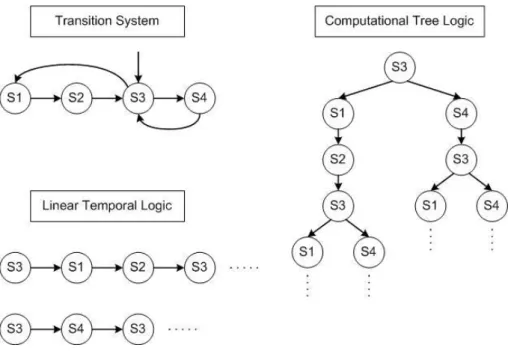
Temporal logic can be used to describe how the behaviours of systems unfold over time. In [70], Pnueli suggested a unified approach to program verification for sequential and parallel systems. The main proof methods suggested in this study was that of temporal reasoning about systems. And then, Manna and Pnueli firstly proposed the use of temporal logic for reasoning about the properties of reactive systems [55]. This logic uses a set of atomic properties, Boolean connectives, and four temporal operators. The temporal operators normally meanfutureoperators: invariant, eventually, next, anduntil. There are two different underlying structures of time. The first one is Linear Temporal Logic (LTL) [59], and the second one is Computational Tree Logic (CTL) [71, 72]. The underlying structure of time in the LTL is a totally ordered set. On the other hand, in the CTL the underlying structure of time is branching tree-like as depicted in Figure 2.2.
The LTL uses four temporal operators: X(next),G(invariant),F(eventually), andU(until), and the CTL uses the temporal operators above mentioned with two path quantifiers:A(for all paths) andE(a path exists). Even though the CTL uses the path quantifiers additionally, the expressive power of the CTL and LTL are not comparable because there are the properties that can be expressed in the LTL but cannot be expressed in the CTL, and vice versa. But there is a temporal logic, CTL*, which is definitely more powerful than the CTL and LTL. It uses the temporal operators of the LTL and the path quantifiers of the CTL, but differently from the CTL its temporal operators can be used without path quantifiers. Therefore, CTL can be viewed as a fragment of CTL*. There is another fragment of CTL*,
Figure 2.2: Representations of LTL and CTL for a given transition system
Propositional Linear Temporal Logic (PLTL) [57]. PLTL [73] is a linear time logic with past modalities Y (yesterday) and S (since). Because it does not use the path quantifiers like LTL, it only deals with the set of executions and can not examine alternative executions which split off from one state at each time step where a nondeterministic choice is possible. Based on this original temporal logic, Real-Time Temporal Logic (RTTL) is extended to apply automated verification to real-time distributed systems for safety-critical applications [74, 75].
2.3 Model checker
2.3.1 Why model checking?
Model checking[59, 57] can explore all possible systems states in a brute-force manner. In other words, model checking tool examines all possible system sce-narios in a systematic manner and shows that a given system satisfies a certain property. There are some advantages of model checking which induce industry an increasing interest. Firstly, recently-developed model checking tools can handle state spaces of about 108 to 109 states with explicit state-space enumeration and
and tailored data structures. Moreover, model checking can reveal even the subtle errors that may remain undiscovered by testing and simulation because they are aimed at tracing the most probable defects. Additionally, the properties of interest can be checked individually when model checking is used. Therefore, users can focus on the essential properties at every phase of development. The autonomous multi-agent systems dealt with in this thesis can be considered as prototype. They are not fully-developed system and have potential to be extended. Hence, a ver-ification tool for these systems must have ability to deal with increasing state space. Moreover, it needs to discover any error that can be created from evolution of system/specification and does not require complete specification in the initial phase of study. Consequently, model checking is the most proper technique to verify the systems in this study.
2.3.2 Denition and requirement of model checker
Model checking is an automated procedure that performs an exhaustive or sym-bolic search of the system’s state-space and determines the truth value of the specification in question, i.e., an automated formal methods. Moreover, the model checking always terminates with a‘true’ or ‘false’ answer and provides a coun-terexample which can be used to check the system errors and to take corrective actions. The algorithms used in model checking rely on the explicit construction of the finite state model targeted for verification. When applied to finite state systems, model checking can be performed automatically. In the case of complex systems, such an approach rapidly leads to the state explosion problem. There-fore, the principles underlying these model checking algorithms have evolved continuously, based on the type of temporal logic used in the specification. Usu-ally, model checking involves satisfying theneverclaims, where the aim is to show that a (undesirable) specification (or condition) is never reached.
The model checking problem of a system involves the verification of certain fundamental system properties:reachability, safety, livenessandfairnessproperties. The details of each property follows as:.
• safety property represents that, under certain conditions, something never
occurs.
• livenessproperty means that, under certain conditions, something will
ulti-mately occur.
• fairness property implies that, under certain conditions, something will (or
will not) occur infinitely often.
Reachabilityis simple to express such as ‘the program can enter a critical section’ or ‘the program cannot reach the crash state.’ They can also be conditional like ‘critical section can be entered without n=0’. Reachabilitymay also apply to any reachable state. LTL is poorly suited for specifyingreachabilityproperties because it implicitly quantifies over all computation paths. Thus, LTL can only express reachabilitynegatively such as ‘something is not reachable’.
Safetyconditions are generally of the form ‘both processes will not be in the critical section simultaneously.’ In general, safetystatements express that an un-desirable event will not occur.
Examples ofliveness include ‘any request will ultimately be satisfied’ or ‘the program will terminate.’ As the terminology suggests, the general meaning of theliveness property is to state that some event will occur in the end. From an utilitarian point of view, thelivenessproperty yields no information.
A classic fairness statement is the ‘if access to a critical section is infinitely often requested, then access will be granted infinitely often.’ In practice, the fair-ness properties are very often used to describe some form of non-deterministic sequences, in particular when dealing with concurrent system [76]. Fairness assumptions are requisite to establish liveness properties or other properties im-plying that the system makes progress [59]. There are two different types of fairness constraints: strong fairness and weak fairness. Strong fairness represents that an activity infinitely often occurs, but is not necessarily always. In other words there may be finite periods during which the activity does not occur. On the other hands, weak fairness means that an activity continuously happens and no period is allowed in which the activity does not happen.
2.3.3 Model checking tools
Many researchers have used model checking to deal with finite state concurrent systems, especially to verify hardware and software such as complex sequential circuit designs and communication protocols [19]. Also, many automatic tools for model checking, i.e., model checkers have been developed for a long time. As examples of earlier model checkers, there are Simple Promela Interpreter (SPIN), Symbolic Model Verifier (SMV/NuSMV), UPPAAL, KRONOS, HYTECH and so on.
The SPIN is a model checker for the LTL and was developed for the verification of protocols and software in the 1980s. As its programming language is PROcess Meta Language (PROMELA), the user must translate the system of interest into the PROMELA. The SPIN is known as a mature tool but cannot handle unbounded data.
The SMV is one of the model checking tools using Ordered Binary Decision Di-agrams (OBDD) and based on the model checking techniques for the CTL. NuSMV, a re-implementation of SMV, applies the bounded model checking methods for the LTL in addition to the OBDD for the CTL. In the same way as the SPIN, the SMV and NuSMV need to translate the system into their own input languages. Generally, these translations in the aforementioned tools require simplification or abstraction of the systems, by which false counter-examples can be caused.
UPPAAL[77] is an integrated tool for modelling, simulating, and verifying real-time systems. It is able to analyze networks of timed automata with binary synchronization. The timed systems are described usinggraphical editorpart and then users can perform simulation of the systems and check the behaviour of the designed systems usinggraphical simulator. At last,verifiercheck the reachability properties of the systems.
KRONOS[78] is a model checker for the TCTL (Timed Computation Tree Logic)properties of a timed automaton. The timed automaton can be given in textual form starting from a system consisting of some components. After that, KRONOS computes the automaton corresponding to the synchronized product.
HYTECH[79] is developed to analyze linear hybrid automata at Cornell Uni-versity. A set of linear hybrid automata synchronized by some common transi-tions can be used in HYTECH. It computes the subsets of the global state space
from the automata in a textual form. Subsequently, the result of the computation provides information about the behaviour of the system.
There are more recently evolved model checking tools. For instance, BLAST [80] was developed to check the temporal safety properties of C programs au-tomatically. It verifies a program by the following steps. Firstly, a program is represented by using a set of control flow automata. And then BLAST constructs an abstract reachability tree to present a portion of the reachable state space of the program. Finally, it shows whether the error configuration is never reached or not. BLAST was developed by the University of California and can be used to prove the memory safety of C programs.
SLAM [81] verifies the temporal safety properties of Window APIs imple-mented in the C programs. The analysis engine of the SLAM is SDV (Static Driver Verifier) which checks whether a device driver correctly interacts with the Win-dow operating system kernel or not. Its constructs a Boolean program which has the same control-flow structure of the original C program but consists of only Boolean variables. And then these Boolean variables track important predicates over the states in the original program using the predicate abstraction technique to perform reachability analysis and counter-example driven refinement.
Zing [82] is a framework for software model checking. This project aimed to build a flexible and scalable model checking infrastructure for concurrent soft-ware. It includes a modelling language, a state explorer, and an automatic model generator from common programming languages such as Visual Basic, C/C++, C#, and so on.
Java Path Finder [83] was started from the translation from Java to Promela. Nowadays it is based on a Java Virtual Machine, which is a state software model checker for Java. The same as other software model checker, it explores all execution paths of a program and find violations of properties.
MAGIC [84] is another model checker that can be applied to C programs. Its main task is to check the consistency between software specifications and implementations.
There is one more model checker named as MCMAS[42]. The goal of the MC-MAS is the development of formal verification techniques for multi-agent systems using model checking techniques. The systems used in the MCMAS are
deon-tic interpreted systems. For the purpose of specification of multi-agent systems, CTLKD−AD,C formulae are used. The CTLKD−AD,C stands for
Alternating-time Temporal Epistemic Logic (ATEL) extended with the operators for correct behaviour. It means that this multi-modal logic includes temporal, epistemic, correct behavioural and strategic operators.
2.3.4 Selection of model checking tool: MCMAS
In this thesis, the MCMAS is adopted to verify a heterogeneous multi-agent autonomous system because it is more suitable for multi-agent system than the other tools and has no limitation of dealing with a large multi-agent system composed of many autonomous agents. MCMAS [42] is based on OBDD and uses its own language ISPL to describe deontic interpreted systems. OBDD is a canonical graph of Boolean function and acquired by imposing an ordering on the Boolean variables and reducing the graph of the Boolean function [85]. Originally, binary decision diagrams were introduced by Lee [86], and further studied and made known by Akers [87] and Boute [88]. Based on their studies, the full potential for efficient algorithms derived from the data structure was introduced by Randal Bryant. He suggested a fixed variable ordering for canonical representation and shared sub-graphs for compression as above-mentioned[85, 89, 90].
An interpreted system which can be used in MCMAS is represented with a tuple IS as follows.
IS =D(Li,Acti,Pi,ti)i∈{1,···,A},(LE,ActE,PE,tE),I,V
E
(2.1) where A is the number of agents in the system and E represents Environment Agentwhich can be used to describe the environment in which agents interact. Li are local states of agent i, Acti represents a set of actions, and Pi and ti mean
protocolsPi : Li →2Acti and evolution functionsti :Li×LE×Act→Lieach, where
Act=Act1× · · · ×ActA×ActE. Additionally,Iis a set of possible initial global states
andVis an evaluation relation,V⊆S×AP, in a given set of atomic propositions
AP. As described in the equation of evolution functions, evolution of one agent is affected by not only its own local state and action but also local state and action ofEnvironment Agentand actions of the other agents. By this way, MCMAS can
practice interactions among individual agents and environment to construct a multi-agent system.
The ISPL has six essential parts to represent an above-described interpreted system: Environment Agent, Agent, InitStates, Evaluation, and Formulae. In the Agent parts including Environment Agent, a Kripke model can be constructed using state variables, actions, protocols, and evolution. Possible worlds can be defined as state variables,labelling functionis described in protocol section using properties defined as actions, and rules in evolution representaccessibility relation among possible worlds. In the InitStates part, the initial states of all agents are defined. Finally, the atomic propositions and their valid states are each declared in the Evaluationpart. Using these propositions, the properties which we want to verify are expressed in theFormulaepart.
Surveillance Mission by a Single MAV
3.1 Scenario denition
To start with a simple multi-agent system, a part of decision making model used in the MoD Grand Challenge1is considered in this chapter. The Grand Challenge
was a competition to look for innovative ideas and the technology to solve the military problem faced in a hostile urban environment. The scenario was that the competitors were in command of a troop operating apart from them and the troop made a reconnaissance to find threats. The competitors had already been aware of potential danger points where the enemy may lie in ambush, but, there were snipers, danger, and improvised explosive devices all around. Therefore, they had to discover whether the hostile urban environment is safe or not finding and removing hidden threats using intelligence graphic information gathered from multiple joint and coalition sources such as satellite and manned/unmanned aerial vehicle feeds. Figure 3.1 shows the town where the final demonstration was set up [91].
Cranfield University participated in this project as a member of the Stellar team and used the Kripke models to describe autonomous systems: Ground Control System (GCS), Micro Aerial Vehicle (MAV), High-Level Unmanned Aerial Vehicle (HLUAV), and Unmanned Ground Vehicle (UGV) which implemented missions for the MoD Grand Challenge [47]. These integrated mixed vehicle systems demonstrated by the Stellar team found targets with complete coverage and no false alarms. Moreover, despite the bad weather, Stellar team detected system failure and used their operators effectively during the search, so they could create a clear and accurate report upon completion of the task. As a consequence, Stellar team became the winner and won the RJ Mitchell Trophy as shown in Figure 3.2. As an initial step, only the GCS and MAV are selected from the aforementioned Grand Challenge scenario to abstract the decision making model from one of their missions. An overview of the mission between the GCS and MAV is depicted in
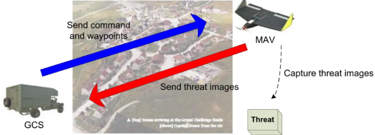
Figure 3.1: Sky view of Copehill Down
Figure 3.3. The main mission of the MAV is to obtain images of potential threats. For this, the MAV follows the waypoints commanded from the GCS, captures the images and sends them back to the GCS. Then, the images obtained from the MAV can be used for threat analysis, which decides whether each threat needs to be verified further by the UGV. Moreover, the MAV will automatically land by following safety requirement in cases: 1) the communication channel to the GCS is lost, 2) the GCS sends a landing command.
Figure 3.3: The scenario overview of surveillance mission by a single MAV in perspective of Grand Challenge mission
3.2 Kripke modelling of multi-agent system
3.2.1 Kripke model for MAV
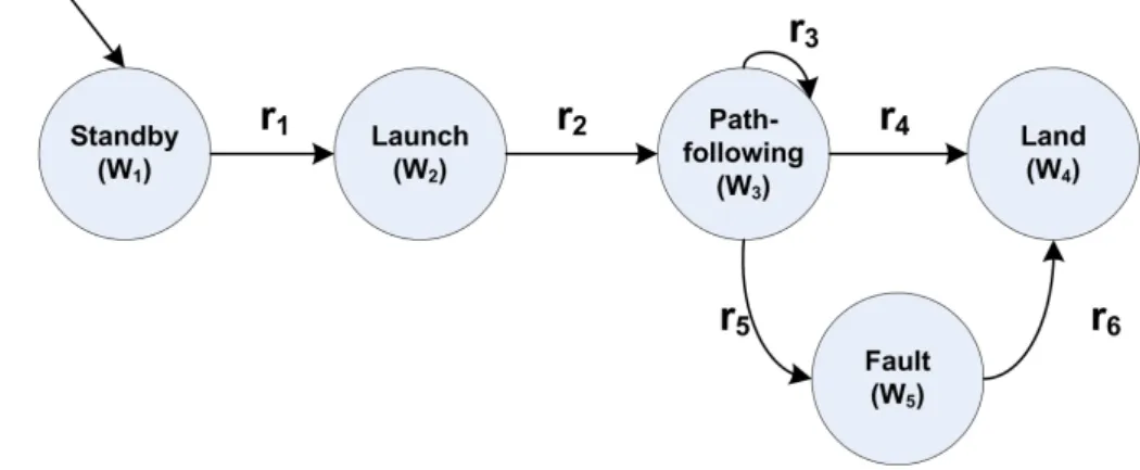
The behaviours of the MAV can be defined as follows: launch, path-following, capturing images, sending images, and land. However, in a real situation, it is impossible for the MAV to transit from path-following to capturing/sending images state because the MAV follows the waypoints capturing or sending images simultaneously. Therefore, the behaviours performed in the same time need to be integrated to construct a correct Kripke model. Figure 3.4 shows the modified Kripke model for the MAV. In the state of the path-following the MAV performs a waypoint following manoeuvre, captures the target images and sends them to the GCS.
Figure 3.4: Kripke model for the MAV
• (W1−W2): The transition happens if the MAV receives the launching
com-mand. r1 =
true if the MAV receives the launching command successfully. f alse otherwise
• (W2−W3): The transition happens if the MAV has launched successfully.
r2 =
true if the MAV has been launched successfully. f alse otherwise
• (W3−W3): The MAV follows the waypoints, captures and sends the target
images to the GCS in normal situation. r3 =
true if the MAV performs path-following and its mission successfully.
f alse otherwise
• (W3−W4): The transition happens if the MAV needs to land.
r4 =
true if the GCS sends the landing command or communication is lost.
f alse otherwise
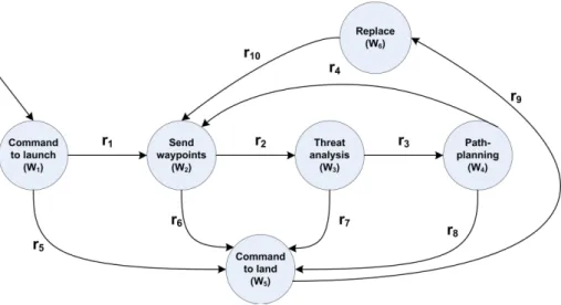
3.2.2 Kripke model for GCS
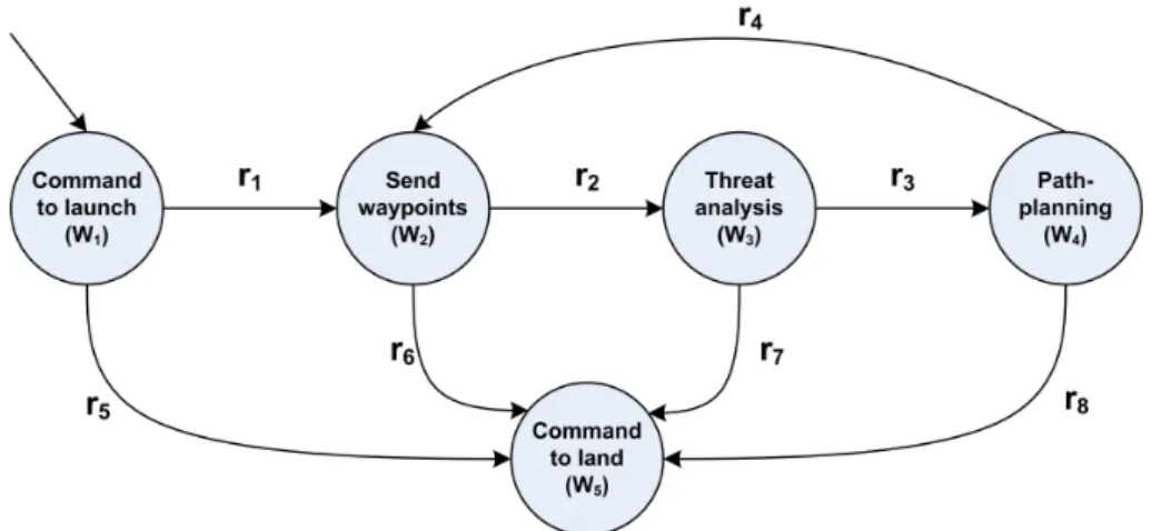
To construct the Kripke model for the GCS, the behaviours of the GCS related with MAV mission can be defined as the following states: launch-commanding, waypoint-sending, threat analysis, path-planning, and land-commanding. In the path planning state, the GCS calculates the next waypoint that the MAV has to visit.
Figure 3.5: Kripke model for the GCS
• (W1−W2): The transition happens if the GCS sends the launching command.
r1 =
true if the GCS sends the launching command successfully. f alse otherwise
• (W2−W3): The transition happens if the MAV sends the threat images.
r2 =
true if the GCS receives the threat images from the MAV. f alse otherwise
• (W3−W4): The transition happens if the GCS has finished threat analysis.
r3 =
true if the GCS has finished threat analysis. f alse otherwise
• (W4−W2): The transition happens if the GCS has finished path-planning.
r4 =
true if the GCS has finished the calculation of new waypoints. f alse otherwise
• (W1−W5),(W2−W5),(W3−W5),(W4−W5): The transition happens if the GCS
has decided to command landing to the MAV. r5,r6,r7,r8 =
true if the GCS sends the landing command to the MAV because of the emergency or mission completion. f alse otherwise
3.3 Modelling of properties to be veried
There are two properties to be verified in this scenario. The first property is‘The MAV must land or stay at standby state if the GCS sends the landing command or the
communication channel is lost.’ This is an important property in unmanned systems by the safety requirement. The second property to be verified is‘The MAV must be launched if the GCS sends the launching command successfully.’ This property is defined to check whether the MAV follows the command from the GCS correctly or not. These properties can be expressed in CTL as follows.
AG(((GCS.state=LC)∨(Environment.state=LO))
→AX((MAV.state=SB)∨(MAV.state=LA))) (3.1)
AG(((GCS.state=CL)∧(Environment.state=CO))
→AX((MAV.state=L))) (3.2)
where‘LC’and ‘CL’meanCommand to LandandCommand to Launch states of the GCS, respectively. Similarly‘SB’, ‘L’, and‘LA’ represent Standby, Launched, and Land states of the MAV. The states related with the state of communication are represented by‘LO’,Communication Lost, and‘CO’,Communicating.
3.4 Model checking with MCMAS
3.4.1 MCMAS model
To perform the model checking automatically, the decision making behaviours of multi-agent system described in Section 3.2 are translated into ISPL, the input language of MCMAS. Figure 3.6 depicts the elements of the ISPL for the verifica-tion.
Figure 3.7 shows the entire ISPL code which represents allAgents, initial states of each agents,Evaluation, andFormulae. Environment Agentis constructed to rep-resent the states of communication between the GCS and MAV. It has two states, communicating and lost, and available actions, send/receive and none. The Kripke models of the GCS and MAV are represented inAgentpart by means of interpreted system formulation explained in Section 2.3.4. The Agent GCS consists of five states as described in the Kripke model: launch-commanding state, waypoint-sending state, threat analysis state, path-planning state, and land-commanding state. Each state has an action equivalent to their state and, additionally, com-manding landing action for emergency. The states of the MAV inAgent MAVare standby state, launch state, path-following state, and land state. The standby state, launch state, and land state have only one action respectively which means state completion. While the path following state has three different actions: waypoints following, sending images to the GCS, and landing. As explained in Section 2.3.4, Evolutionparts ofAgent GCSandAgent MAVshow that all evolution of individ-ual agent are established under interactions of locals and actions possessed by every agents and environment at that phase. To help to find the interaction part inEvolution, local states and actions of environment and the other agent used for each agent’s evolution are marked with yellow line in Figure 3.7. The proper-ties discussed in Section 3.3 are described inFormulaeas CTL expression and the atomic propositions used to describe these properties are defined inEvaluation. The initial states of the GCS and MAV are declared as launch-commanding state and standby state respectively as depicted in each Kripke model. In case ofAgent Environment, communicating is assigned as the initial state for the nominal state of environment.
3.4.2 Verication results
The properties described in Section 3.3 are verified by means of MCMAS model checking command, and the results of them are shown in Figure 3.8
Figure 3.8: Verification results
Equation 3.1 has been verified as‘true’, but Equation 3.2 has‘false’result. Using the counterexample/witness option, an error trace can be acquired and discussed in the next section.
3.4.3 Analysis and discussion
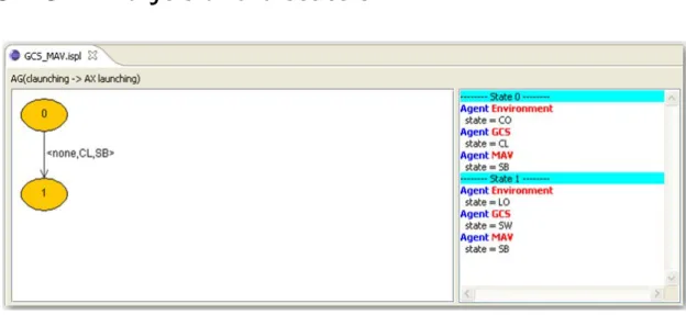
Figure 3.9: The counterexample of formula 2
Formula 2 is defined to check whether the MAV follows the command from the GCS correctly or not. Therefore, the MAV must be launched if the GCS sends the launching command successfully by designer’s intention. However, the
verification result of formula 2 represents that this property is violated in some branch of the computational tree. The counterexample shows the case in which the communication has been lost after the GCS sent the launching command. In this situation, the MAV can not receive the command and can not help staying at the standby state. That is, the MAV can not launch because the GCS sent the launching command successfully but this command has not been sent to the MAV. This case has not yet been considered the stage of property modelling. In this scenario, communication between the agents is the most important part to perform cooperation correctly. Through the communication, agents share the information of targets, and transmit the command and waypoints. Therefore it is essential not only for mission execution but also for safety. However, the counterexample illustrated in Figure 3.9 showed that the mission cannot even be started when the communication has been lost. In real world, there is no almighty solution against communication loss. If communication between remote agents from each other is lost, the only option which they can take is to return to a base safely. Therefore, an interruption of mission execution by communication loss can not be conquered. Another possible case causing the interruption of mission completion is irrecoverable malfunction of agents. If agents have problems such as mechanical fault, disorder of electrical devices, or false of main controller and these problems can not be repaired for themselves, missions can not be executed any longer, either. Accordingly, the only alternatives for improving the probability of mission success are to use an additional agent or redundant communication channels.
3.5 Extended scenario denition
As a result of discussion in Section 3.4.3, the scenario is extended as follows: If the MAV malfunctions in the path following state, the GCS commands the MAV to land and a new MAV to launch. Then the new MAV performs the mission as a substitute for the old MAV. The extended model cannot solve the problem of communication loss basically, however, it can certainly improve the probability of mission completion. To construct the modified scenario the Kripke models of the GCS and MAV have to be changed with additional states.
3.6 Kripke modelling of extended scenario
3.6.1 Kripke model for MAV and substitute MAV
The new behaviour of the MAV aims to overcome malfunction during performing the mission. Figure 3.10 shows the modified Kripke model for the MAV and the substitute MAV.
Figure 3.10: Kripke model for the MAV and the substitute MAV
The additionalaccessibility relationsare described below:
• (W
3−W5): The transition happens if the MAV detects its malfunction during
path-following. r5 =
true if the MAV detects its malfunction during the mission. f alse otherwise
• (W5−W4): The transition happens if the GCS commands to land because of
malfunction. r6 =
true if the GCS commands to land because of malfunction. f alse otherwise
3.6.2 Kripke model for GCS with additional behaviour
To combine the replacement behaviour into the original Kripke model for the GCS, the replacement state is added as depicted in Figure 3.11.