Algorithm
Features
• Cost-effective and flexible 3-phase induction motor drive • Interrupt driven
• Low memory and computing requirements
1.
Introduction
Electrical power has been used for a long time to produce mechanical motion (either rotation or translation), thanks to electromechanical actuators. It is estimated that 50% of the electrical power produced in the United States is consumed by electrical motors. More than 50 motors can typically be found in a house, and nearly as many in a car.
To preserve the environment and to reduce green-house effect gas emissions, gov-ernments around the world are introducing regulations requiring white goods manufacturers and industrial factories to produce more energy efficient appliances. Most often, this goal can be reached by an efficient drive and control of the motor speed. This is the reason why appliance designers and semiconductor suppliers are now interested by the design of low-cost and energy-efficient variable speed drives. Because of their high robustness, reliability, low cost and high efficiency ( 80%), AC induction motors are used in many industrial applications such as
• appliances (washers, blowers, refrigerators, fans, vacuum cleaners, compressors …);
• HVAC (heating, ventilation and air conditioning);
• industrial drives (motion control, centrifugal pumps, robotics, …); • automotive control (electric vehicles)
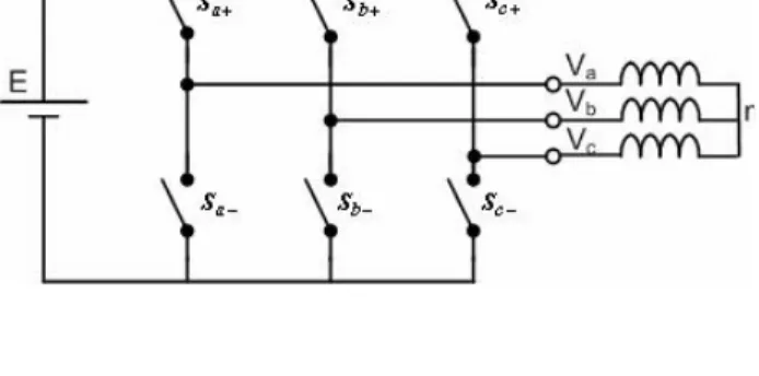
However, induction motors can only run at their rated speed when they are connected to the main power supply. This is the reason why variable frequency drives are needed to vary the rotor speed of an induction motor. The most popular algorithm for the control of a three-phase induction motor is the V/f control approach using a natural pulse-width modulation (PWM) technique to drive a voltage-source inverter (VSI), as shown on Figure 1-1. The aim of this application note is to show how these techniques can be easily implemented on a AT90PWM3, an AVR RISC based microcontroller dedicated to power control applications.
≈
7545A–AVR–12/05
8-bit
Microcontrollers
Figure 1-1. Typical Structure of an Inverter-fed Induction Motor
2.
AT90PWM3 Key Features
The control algorithms have been implemented on the AT90PWM3, a low-cost low-power sin-gle-chip microcontroller, achieving up to 16MIPS and suitable for the control of dc-dc buck-boost converters, permanent magnet synchronous machines, three-phase induction motors and brushless DC motors. This device integrates:
- a microcontroller with an 8-bit AVR advanced RISC architecture (similar to the ATmega 88),
- 8 kBytes of In-System-Programmable flash memory allowing up to 4096 instructions for the boot program and the application program,
- 512 bytes of static ram to store variables and lookup tables used in the application program, - 512 bytes of EEPROM to store configuration data and look-up tables,
- one 8-bit timer and one 16-bit timer,
- a programmable watchdog timer with an internal oscillator, - an 11-channel 10-bit ADC and a 10-bit DAC.
The main features that make this device suited to motor control applications are the three “power-stage controllers” (called PSC). These peripherals are 12-bit up/down counters with two
comparators, whose output can drive the power transistors of an inverter leg. This allows to gen-erate any three-phase waveform by pulse width modulation, with an easy management of the inverter dead times.
full range. This allows to use a sinusoidal steady state model of the induction motor, in which the magnitude of the stator flux is proportional to the ratio between the magnitude and the frequency of the stator voltage. If this ratio is kept constant, the stator flux will remain constant, and so the motor torque will only depend on the slip frequency.
More precisely, starting from the usual model of an induction motor expressed in a fixed refer-ence frame
where , , , , are respectively the stator voltage, stator and rotor magnetic fluxes,
stator and rotor currents, and and are respectively the global stator
resistance, rotor resistance, stator inductance, rotor inductance, global leakage inductance and mechanical pulsation. If the motor is fed with a sinusoidal 3-phase voltage with a pulsation
, the steady-state currents in the rotor and the stator will also be sinusoids with
pulsation : and . The previous equations lead to
, and , with
and . Hence, the rotor magnitude can be kept
constant if the ratio is kept constant. At high speed, ,and the rotor flux
magnitude is kept constant if the ratio is kept constant: .
The motor torque is then proportional to the slip frequency: . These
expres-sions show that a desired motor torque and a desired
motor speed can be obtained if . At low speed, , and
. When the stator frequency fails under a given frequency threshold (called the boost frequency), the voltage magnitude must be kept at a given level (called the boost voltage) to keep the rotor flux magnitude constant. At the opposite, when the frequency becomes higher than the rated value, the voltage magnitude is also kept to the rated value, to take the saturation of the inverter into account. The rotor flux is no more constant and the torque decreases.
p
I
I
L
p
C
I
L
I
L
I
L
I
L
I
R
j
dt
d
V
I
R
dt
d
m m r s m em s m r r r r m s s s r r r m s s s s sω
φ
φ
φ
ω
φ
φ
=
Ω
=
+
=
+
=
=
+
−
=
+
);
Im(
2
3
;
;
;
0
;
* s V φs φr Is Ir , s R Rr, Ls, Lr, Lm ωm , s ω Vs=Vsmejωst s ω j( st s) sm s I e I = ω +ϕ j( st r) rm r I e I = ω +ϕ s lp s r r s V L j R I Δ + = ω Ir=− jLmΔωslpVs φr=LmΔRrVs ωslp=ωs−ωm s slp m slp r r s s s jL R jL L R ω )( ω ) 2ω ω ( + + + = Δ φrm Δsm V s s rL R j ω ≈ Δ s sm V ω s sm s m sm s s r r m rm RLLRω V LL Vω φ ≈ = slp r rm em p R C φ2 ω 2 3 = em C m ω 3 2 2 rm r em m s Cp R φ ω ω = + Δ≈RsRr s s m r ≈LR V φFigure 3-1. Stator Voltage Magnitude Versus the Stator Frequency Deduced from the V/f Principle
Roughly speaking, the scalar V/f control principle consists in feeding the motor windings with a 3-phase sinusoidal voltage whose amplitude is proportional to the frequency, except below the boost frequency and over the rated frequency, as shown on Figure 3-1. In practice, the slope that defines the relation between the voltage magnitude and the voltage frequency is deduced from the rated terminal supply voltage and the rated supply frequency written on the motor name plate, and the boost frequency is chosen equal to a percentage (say 5%) of the rated frequency.
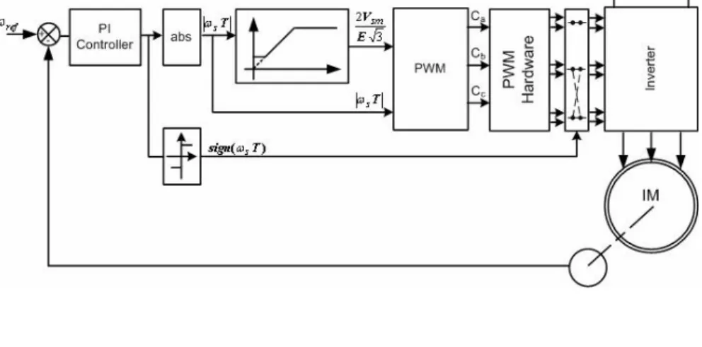
This principle can be used to build a speed control loop (Figure 3-2.) in which the difference between the desired speed and the measured speed feeds a PI controller that determines the stator voltage frequency. To decrease the complexity of the controller, the input of the V/f law and of the space vector PWM algorithm is the absolute value of the stator voltage frequency. If the output of the PI controller is a negative number, two of the switching variables driving the power transistors of the inverter are interchanged. It should be noticed that the control principle described here can only be used in applications where the speed is kept constant whatever the load torque. Applications where the load torque must be kept constant whatever the motor speed require stator current measurements and more sophisticated control principles.
Figure 3-2. Block-diagram of a V/f Speed Control Loop System
3.3
The Natural PWM Principle
So as to feed the stator windings with a 3-phase sinusoidal voltage through an inverter, a first solution is to use a sine table to generate three sine waves with 120 degrees phase shift to each other. For this, the stator pulsation is used to feed three discrete-time integrators which com-pute the instantaneous phase of each stator voltage,
with , , , being the sampling period of the control algorithm.
When one of these angles becomes higher than , is subtracted to it to keep it between 0 and . A sine table is the used to compute the three voltages that should be applied to the stator,
where is the stator voltage magnitude deduced from the constant Volts per Hertz
prin-ciple and .
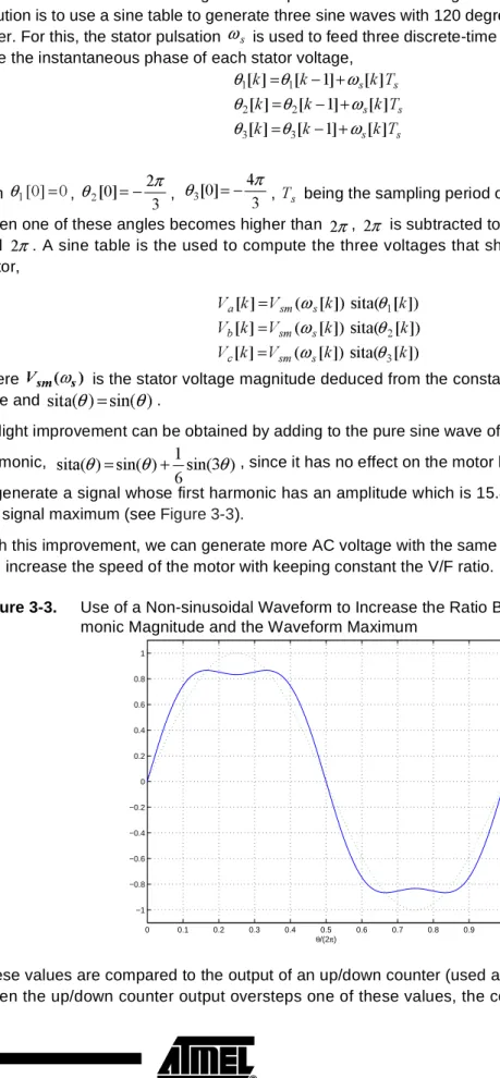
A slight improvement can be obtained by adding to the pure sine wave of the sine table a third
harmonic, , since it has no effect on the motor behavior and it allows
to generate a signal whose first harmonic has an amplitude which is 15.47% higher ( ) than the signal maximum (see Figure 3-3).
With this improvement, we can generate more AC voltage with the same DC bus voltage, so we can increase the speed of the motor with keeping constant the V/F ratio.
Figure 3-3. Use of a Non-sinusoidal Waveform to Increase the Ratio Between the First Har-monic Magnitude and the Waveform Maximum
These values are compared to the output of an up/down counter (used as a triangle generator). When the up/down counter output oversteps one of these values, the corresponding output of
s ω s s s s s s T k k k T k k k T k k k ] [ ] 1 [ ] [ ] [ ] 1 [ ] [ ] [ ] 1 [ ] [ 3 3 2 2 1 1 ω θ θ ω θ θ ω θ θ + − = + − = + − = 0 ] 0 [ 1 = θ 3 2 ] 0 [ 2 π θ =− 3 4 ] 0 [ 3 π θ =− Ts π 2 2π π 2 ]) [ sita( ]) [ ( ] [ ]) [ sita( ]) [ ( ] [ ]) [ sita( ]) [ ( ] [ 3 2 1 k k V k V k k V k V k k V k V s sm c s sm b s sm a θ ω θ ω θ ω = = = ) ( s s
m
V ω)
sin(
)
sita(
θ
=
θ
) 3 sin( 6 1 ) sin( ) sita(θ
=θ
+θ
3 2 0 0.1 0.2 0.3 0.4 0.5 0.6 0.7 0.8 0.9 1 −1 −0.8 −0.6 −0.4 −0.2 0 0.2 0.4 0.6 0.8 1 θ/(2π)the comparator toggles. As a result, the duty cycle of each PWM channel is proportional to the corresponding stator voltage value. Since this up/down counter with three comparators would be very heavy to implement by software, such a device must be included in a microcontroller so as to suit AC motor control applications. This is of course the case of the AT90PWM3, which pro-vides three power stage controllers (PSCs). Taking the first phase as an example, the duty cycle stored in the compare register of the corresponding PSCs will be proportional to
, with , and are respectively the highest value of the
stator
voltage magnitude and the dead time of the inverter switches. The resulting data-flow diagram is shown on Figure 3-4.
Figure 3-4. Natural PWM Data Flow Diagram
)
]
[
1
(
2
smax a sV
k
V
T
α
+
s T δ α =1−2V
smaxδ
3.4
How Many Bytes are Needed to Store a Sine Table
As presented in the previous section, the natural PWM algorithm requires a sine table to com-pute for all values of between 0 and . Thanks to the properties of the trigonometric functions, several solutions are possible to reduce the length of this look-up table. The most effi-cient uses a look up table of the values of the sinus function for between 0 and only, since
for between and
for between and
for between and
for between and
for between and
However, this solution does not easily allow to add a third harmonic to the sinus function, as explained in the previous section.This is the reason why we advise to use a look-up table
with the values of either or for between 0 and , and to use
the following relationships to compute between and :
for between and
for between and
for between and
The latter solution allows to easily interchange between the two possible look-up tables.
3.5
The PI Regulator Principle
A PI controller is an algorithm that can be implemented without resorting to any heavy control theory. The aim of such an algorithm is to determine the plant input (in our case the stator volt-age frequency) that will make the measured output (in our case the speed of the rotor) reach the reference (the speed the user wishes to have). PI stands for Proportional and Integral, two terms which describe two distinct elements of the controller:
- a proportional term, which is equal to the product of the error signal (the measured plant output subtracted to the reference) by a constant called the proportional gain. The proportional term mainly determines the short-term behavior of the controller since it determines how the controller strongly reacts to reference changes;
- an integral term, which adds long-term precision to the controller. This term is the product of the sum of all the previous error signal values by a constant called the integral gain. This sum keeps all the previous error signal values in memory, and evolves as long as the error is not
)
sin(
θ
θ
2π θ 3 π ) 3 2 sin( ) 3 sin( ) sin(θ = θ−π + π −θ θ 3 π 3 2π ) sin( ) sin(θ = π−θ θ 23π π ) sin( ) sin(θ =− θ−π θ π 3 4π ) 3 5 sin( ) 3 4 sin( ) sin(θ =− θ− π + π −θ θ 3 4π 3 5π ) 2 sin( ) sin(θ =− π−θ θ 3 5π π 2 )sita(θ sin(θ) sin(θ)+61sin(3θ) θ
2 π ) sita(θ 2 π 2π ) ( ) (θ =sitaπ −θ sita θ 2 π π ) ( ) (θ =−sitaθ−π sita θ π 32π ) 2 ( ) (θ =−sita π−θ sita θ 2 3π 2π
zero. It allows the controller to cancel the difference between the measured output and the refer-ence, but it usually makes the closed loop system slower and decreases its stability, however. These two terms are sometimes added to a third one, proportional to the derivative of the error signal. The resulting regulator is then called a PID (Proportional, Integrator and Derivative). To control the speed of and induction motor by the V/f principle, this third term is not useful. It increases the speed of the closed loop, but it also derivates noises and it decreases the stability of the closed loop. So, the D term is tricky to adjust.
3.6
Sensors for Motor Control
Speed sensors play a critical role in a control loop. Several solutions are possible to obtain the speed and direction of the rotor.
The most precise, but also the most expensive, is to use absolute or incremental encoders. These optical sensors may be as expensive as the induction motor itself.
Another solution that we used in our experiments is to use the output of a tachometer generator that is connected to the rotor shaft. An analog-to-digital converter is needed to interface the out-put of this sensor with the microcontroller.
A third solution is to use Hall effect sensors. These cheap non-contact sensors are now pro-posed in small IC packages including the sensor and a sensor signal conditioning circuit. They provide an output that can be directly connected to the input-output port of a microcontroller.
4.
Hardware Description (ATAVRMC200)
This application is available on the ATAVRMC200 evaluation board. This board provides a way to start and experiment asynchronous motor control.
ATAVRMC200 main features: • AT90PWM3 microcontroller • 110-230VAC motor drive
• Intelligent Power Module (230V / 370W board sized) • ISP & Emulator interface
• RS232 interface • Isolated I/O for sensors
5.
Software Description
All algorithms have been written in the C language using IAR's embedded workbench and AVR Studio as development tools. The CPU is clocked at 8 MHz using the internal calibrated RC oscillator. In this application, 3 components of the microcontrollers play an important role: The 8-bit timer0 is used to generate an interruption every 1 ms, which is the sampling period of the ADC and of the PIO controller. This timer is used in CTC mode (clear timer on compare) and clocked at 32 kHz. The 16-bit timer1 is free for other tasks.
The PSCs are clocked by the PLL at 64 MHz and are used as three synchronous counters, the third one (PSC2) being the “master” and PSC0 and PSC1 being the “slaves”. In this configura-tion, the modifications of the values of the compare registers of PSC0 and PSC1 are taken into account when the PSC2 compare registers are modified. This allows the three PSCs to evolve simultaneously. They are configured in centered mode with a switching frequency of 12 kHz (the value 2666 is stored in the RB registers, so that the PWM frequency approximately equals 64 MHz/(2* 2666)=12 kHz).
The analog-to-digital converter is also configured to generate an interruption when the conver-sion is finished. This allows to have a constant delay between two samples of the measured speed. The voltage reference of the converter is chosen as Vcc.
The digital-to-analog converter can also be used during the tests to watch how internal variables
evolve. For the natural PWM algorithm, a table of the rounded values of or
for between 0 and 120 is used. The length of this table (121 bytes) is a good trade-off between the size of the available internal memory and the quantification of the rotor shaft speed. For a bidirectional speed control, the values stored in two of the compara-tors are interchanged when the output of the PI regulator is a negative number.
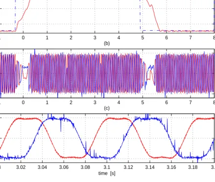
Figure 5-1 and Figure 6-2 show the speed responses and the stator voltages obtained with the microcontroller for speed reference steps between +700 and -700 RPM. These results were obtained on a 750 W induction machine (with a load less than 370W). These figures show that the desired speed is reached after a 1 second transient, and that when the stator frequency obtained at the output of the PI regulator nears zero, the stator voltage magnitude is equal to the boost voltage. These figures also confirm that the same speed and torque can be obtained with a lower stator voltage peak-to-peak amplitude thanks to the use of a third harmonic component, at the price of a less regular transient.
) 480 2 sin( 127 πk )) 480 6 sin( 6 1 ) 480 2 (sin( 127 πk + πk k s ω
Figure 5-1. Experimental Results Obtained with Purely Sinusoidal Lookup Table −1 0 1 2 3 4 5 6 7 8 −500 0 500 (a) speed [rpm] −1 0 1 2 3 4 5 6 7 8 −50 0 50 (b) stator voltage [V] 3 3.02 3.04 3.06 3.08 3.1 3.12 3.14 3.16 3.18 3.2 −50 0 50 (c) time [s] stator voltage [V]
Figure 5-2. Experimental Results Obtained with a Lookup Table Including a Third Harmonic Component
6.
Resources
Code Size: 1 947 bytes
Ram Size: 246 bytes (including sine table)
CPU Load: 30% (without PI regulation) / 55% (with PI regulation)
7.
References
1. W. Leonhard, “Control of electrical drives”, 2nd Ed, Springer, 1996.
2. F.A. Toliyat, S.G. Campbell, “DSP-based electromechanical motion control”, CRC Press, 2004. −1 0 1 2 3 4 5 6 7 8 −500 0 500 (a) speed [rpm] −1 0 1 2 3 4 5 6 7 8 −50 0 50 (b) stator voltage [V] 3 3.02 3.04 3.06 3.08 3.1 3.12 3.14 3.16 3.18 3.2 −50 0 50 (c) time [s] stator voltage [V]
Atmel Corporation
Atmel Operations
2325 Orchard Parkway San Jose, CA 95131, USA Tel: 1(408) 441-0311 Fax: 1(408) 487-2600
Regional Headquarters
EuropeAtmel Sarl
Route des Arsenaux 41 Case Postale 80 CH-1705 Fribourg Switzerland Tel: (41) 26-426-5555 Fax: (41) 26-426-5500 Asia Room 1219
Chinachem Golden Plaza 77 Mody Road Tsimshatsui East Kowloon Hong Kong Tel: (852) 2721-9778 Fax: (852) 2722-1369 Japan 9F, Tonetsu Shinkawa Bldg. 1-24-8 Shinkawa Chuo-ku, Tokyo 104-0033 Japan Tel: (81) 3-3523-3551 Fax: (81) 3-3523-7581 Memory 2325 Orchard Parkway San Jose, CA 95131, USA Tel: 1(408) 441-0311 Fax: 1(408) 436-4314
Microcontrollers
2325 Orchard Parkway San Jose, CA 95131, USA Tel: 1(408) 441-0311 Fax: 1(408) 436-4314 La Chantrerie
BP 70602
44306 Nantes Cedex 3, France Tel: (33) 2-40-18-18-18
Fax: (33) 2-40-18-19-60
ASIC/ASSP/Smart Cards
Zone Industrielle
13106 Rousset Cedex, France Tel: (33) 4-42-53-60-00 Fax: (33) 4-42-53-60-01 1150 East Cheyenne Mtn. Blvd. Colorado Springs, CO 80906, USA Tel: 1(719) 576-3300
Fax: 1(719) 540-1759
Scottish Enterprise Technology Park Maxwell Building
East Kilbride G75 0QR, Scotland Tel: (44) 1355-803-000 Fax: (44) 1355-242-743 RF/Automotive Theresienstrasse 2 Postfach 3535 74025 Heilbronn, Germany Tel: (49) 71-31-67-0 Fax: (49) 71-31-67-2340 1150 East Cheyenne Mtn. Blvd. Colorado Springs, CO 80906, USA Tel: 1(719) 576-3300
Fax: 1(719) 540-1759
Biometrics/Imaging/Hi-Rel MPU/ High Speed Converters/RF Datacom
Avenue de Rochepleine BP 123
38521 Saint-Egreve Cedex, France Tel: (33) 4-76-58-30-00
Fax: (33) 4-76-58-34-80
Literature Requests
![Figure 3-4. Natural PWM Data Flow Diagram])1[2(smaxasVkVT+αTsα=1−2δVsmax δ](https://thumb-us.123doks.com/thumbv2/123dok_us/12491.3001313/6.892.218.803.135.658/figure-natural-data-flow-diagram-smaxasvkvt-αtsα-δvsmax.webp)
![Figure 5-1. Experimental Results Obtained with Purely Sinusoidal Lookup Table −1 0 1 2 3 4 5 6 7 8−5000500(a)speed [rpm] −1 0 1 2 3 4 5 6 7 8−50050(b)stator voltage [V] 3 3.02 3.04 3.06 3.08 3.1 3.12 3.14 3.16 3.18 3.2−50050(c) time [s]stator voltage [](https://thumb-us.123doks.com/thumbv2/123dok_us/12491.3001313/10.892.359.752.182.492/figure-experimental-results-obtained-purely-sinusoidal-lookup-voltage.webp)