Architectural Engineering -- Dissertations and
Student Research Architectural Engineering and Construction, Durham School of
5-2012
Residential Energy Recovery Radiant Heat System
Residential Energy Recovery Radiant Heat System
Scott Sharp
University of Nebraska-Lincoln, ssharp5@huskers.unl.edu
Follow this and additional works at: https://digitalcommons.unl.edu/archengdiss
Part of the Architectural Engineering Commons
Sharp, Scott, "Residential Energy Recovery Radiant Heat System" (2012). Architectural Engineering -- Dissertations and Student Research. 15.
https://digitalcommons.unl.edu/archengdiss/15
This Article is brought to you for free and open access by the Architectural Engineering and Construction, Durham School of at DigitalCommons@University of Nebraska - Lincoln. It has been accepted for inclusion in Architectural Engineering -- Dissertations and Student Research by an authorized administrator of DigitalCommons@University of Nebraska - Lincoln.
By Scott D. Sharp
A THESIS
Presented to the Faculty of
The Graduate College at the University of Nebraska In Partial Fulfillment of Requirements
For the Degree of Master of Science
Major: Architectural Engineering
Under the Supervision of Professor Haorong Li
Lincoln, Nebraska May, 2012
RESIDENTAL FURNACE ENERGY RECOVERY RADIANT HEAT SYSTEM Scott D. Sharp, M.S.
University of Nebraska, 2012 Adviser: Haorong Li
Energy recovery systems aim to recover waste energy that is normally lost to the environment. Waste energy comes in a variety of forms. Many processes involving building HVAC involves transferring energy from one working fluid to another. Governing codes put strict requirements on ventilation requirements for various
occupancy types. Increased ventilation demands more from the HVAC equipment since outdoor air (ventilation air) is being brought into the building and requires tempering in order to retain occupant comfort. The energy required to temper this air increases as ventilation rates increase. Many commercial buildings have implemented exhaust air energy recovery, or runaround loops in order to re-capture the energy in the exhaust air streams.
Residential HVAC systems are no different than commercial systems, just less complex typically. There is little being done to recover energy lost in the residential sector. The commercial industry is much further along in energy recovery systems than the residential sector. This is partially due to the lack of interest by home owners. Residential buildings consumed 35% of the total U.S. natural gas consumption in 2008 accounting for more than $90 billion dollars annually. Typical residential furnaces are 80% thermally efficient. The wasted energy is largely found in the combustion products,
or flue gasses. By recovering heat from the flue gases, this energy can be reclaimed and put to use.
Having a source for energy recovery is only part of the predicament. A desirable application of the recovered energy is also necessary. Home owners need to see a quick payback as well as an incentive in order to be enticed to make capital investments. Without government aid or tax incentives many individuals lose interest.
This thesis researches using energy recovery from residential gas furnaces to apply reclaimed heat to a radiant driveway heating system. The incentive for this application is the not only a maintenance free driveway in the winter, but reduced costs for snow removal.
Author’s Acknowledgements
I want to thank Dr. Haorong Li, Dr. Yong Cho, and Daihong Yu for their advice and guidance through the thesis process. Special thanks go out to Alta Sharp for funding the experimental model that was built to test this theory.
Table of Contents
CHAPTER 1: INTRODUCTION ... 1
1.1. PROBLEM STATEMENT ... 1
1.2. RESEARCH OBJECTIVES ... 2
CHAPTER 2: LITERATURE REVIEW ... 3
2.1. RESIDENTIAL ENERGY CONSERVATION ... 3
2.2. FLUE GAS ENERGY RECOVERY ... 5
2.3. SUMMARY ... 6
CHAPTER 3: DEVELOPMENT OF RESIDENTIAL ENERGY RECOVERY SYSTEM AND APPLICATION ... 7
3.1. INTRODUCTION ... 7
3.2. COMMERCIAL ENERGY RECOVERY SYSTEMS ... 9
3.3. RESIDENTIAL ENERGY CONSUMPTION ... 13
3.4. RESIDENTIAL INDIRECT-FIRED GAS FURNACE OPERATION ... 18
3.5. OPTIONS FOR RESIDENTIAL GAS FIRED FURNACE ENERGY RECOVERY ... 25
3.6. PROPOSED ENERGY RECOVERY SYSTEM ... 28
3.7. ECONOMIC ANALYSIS ... 29
3.7.1. Analysis... 30
CHAPTER 4: INITIAL ANALYTICAL ANALYSIS ... 33
4.1. RADIANT HEATED DRIVEWAY ANALYSIS ... 33
4.3. FURNACE COMBUSTION ANALYSIS ... 43
CHAPTER 5: EXPERIMENTAL TESTING SETUP ... 47
5.1. FLUE GAS ENERGY RECOVERY SYSTEM DESIGN ... 47
5.2. RADIANT HEAT SNOW MELT SYSTEM DESIGN ... 51
5.3. DATA COLLECTION ... 56
CHAPTER 6: EXPERIMENTAL SYSTEM TEST RESULTS ... 61
6.1. INITIAL FLUE GAS ENERGY RECOVERY SYSTEM RESULTS ... 61
6.2. INITIAL RADIANT HEAT SNOW MELT SYSTEM RESULTS ... 63
6.3. FULL SYSTEM TEST AND ANALYSIS ... 65
6.4. FURNACE COMBUSTION ANALYSIS RESULTS ... 71
CHAPTER 7: ANALYSIS AND DISCUSSION... 74
7.1. FLUE GAS ENERGY RECOVERY ANALYSIS AND DISCUSSION ... 74
7.2. RADIANT HEAT SUB-SYSTEM ANALYSIS AND DISCUSSION ... 75
7.3. FURNACE COMBUSTION ANALYSIS AND DISCUSSION ... 75
7.4. UNCERTAINTY ANALYSIS AND DISCUSSION ... 76
CHAPTER 8: CLOSING STATEMENTS ... 78
8.1. CONCLUSION AND RECOMMENDATIONS ... 78
CHAPTER 9: FUTURE CONSIDERATIONS ... 80
9.1. GLYCOL HEATING SOLUTION STORAGE TANK (CLOSED SYSTEM)... 80
9.2. THREE-WAY CONTROL VALVE ... 82
List of Figures
FIGURE 1: RUN AROUND COIL SCHEMATIC (SHAH,2011) ... 11
FIGURE 2: ENTHALPY WHEEL OPERATION (MILLER,2008) ... 13
FIGURE 3: RESIDENTIAL SITE ENERGY CONSUMPTION BY END USE (D&RINTERNATIONAL, LTD.,2011) ... 14
FIGURE 4: AIR COOLED HEAT PUMP IN COOLING MODE ... 16
FIGURE 5: AIR COOLED HEAT PUMP IN HEATING MODE ... 17
FIGURE 6: GAS FIRED DOMESTIC WATER HEATER DIAGRAM (GUADALUPE,2010) ... 18
FIGURE 7: INDIRECT FIRED GAS FURNACE OPERATION (1ST CHOICE HOME INSPECTION SERVICE,2012) ... 19
FIGURE 8: VENTURI-TYPE BURNER SCHEMATIC (FLECK,ARNOLD,ACKERMAN,DALE, KLACZEK,&WILSON,2009) ... 22
FIGURE 9: THEORETICAL DEW POINTS OF COMBUSTION PRODUCTS OF INDUSTRIAL FUELS (2009ASHRAEFUNDAMENTALS,2009) ... 24
FIGURE 10: SIMPLE PAYBACK GRAPH ... 33
FIGURE 11: INITIAL COPPER ENERGY RECOVERY COIL ... 49
FIGURE 12: NATURAL GAS FIRED FURNACE WITH ENERGY RECOVERY ... 50
FIGURE 13: SYSTEM CIRCULATION PUMP ... 51
FIGURE 14: RADIANT HEAT SLAB PROPOSED LOCATION ... 52
FIGURE 15: RADIANT HEAT PIPING SCHEMATIC ... 53
FIGURE 16: RADIANT HEAT SLAP PREPARATION (WWW.RADIANTCOMPANY.COM,2009) 53 FIGURE 17: RADIANT HEATING SYSTEM BEFORE POUR ... 55
FIGURE 19: FINISHED RADIANT HEAT SLAB ... 56
FIGURE 20: RUNAROUND ENERGY RECOVERY SCHEMATIC ... 57
FIGURE 21: INFRARED THERMOMETER ... 58
FIGURE 22: CRAFTSMAN MULTI-METER ... 59
FIGURE 23: COMBUSTION ANALYZER COMPUTER ... 60
FIGURE 24: COMBUSTION ANALYZER PROBE ... 60
FIGURE 25: INDOOR COIL FLUID RETURN TEMPERATURE VS.TIME ... 62
FIGURE 26: GLYCOL SOLUTION RECOVERY CHANGE IN TEMPERATURE ... 63
FIGURE 27: INITIAL SNOW COVER ... 64
FIGURE 28: RADIANT HEATING GLYCOL SOLUTION RETURN TEMPERATURE ... 65
FIGURE 29: DRAINABLE FLUE CONFIGURATION ... 66
FIGURE 30: FULL SYSTEM TEST INITIAL SNOW COVER ... 67
FIGURE 31: HUMAN COMFORT ZONES (2009ASHRAEFUNDAMENTALS,2009) ... 68
FIGURE 32: MODIFIED ENERGY RECOVERY COIL ... 69
FIGURE 33: VELOCITY PROFILES OF FLOW IN PIPES (2009ASHRAEFUNDAMENTALS, 2009) ... 70
FIGURE 34: MODIFIED COIL INSTALLED IN FLUE ... 70
FIGURE 35: FINAL RADIANT SYSTEM RESULT ... 71
FIGURE 36: STORAGE TANK SCHEMATIC DIAGRAM ... 81
FIGURE 37: THREE-WAY VALVE SCHEMATIC DIAGRAM ... 82
FIGURE 38: INITIAL SNOW COVER (TEST 1) ... 89
FIGURE 39: RADIANT SLAB (TEST 1,T=15MIN) ... 89
FIGURE 41: RADIANT SLAB (TEST 1,T=76MIN) ... 90
FIGURE 42: RADIANT SLAB (TEST 1,T=87MIN) ... 91
FIGURE 43: RADIANT SLAB (TEST 1,T=94MIN) ... 91
FIGURE 44: RADIANT SLAB (FULL-SYSTEM TEST T=0MIN) ... 92
FIGURE 45: RADIANT SLAB (FULL-SYSTEM TEST T=2.5HOURS) ... 92
FIGURE 46: RADIANT SLAB (FULL-SYSTEM TEST T=4.1HOURS) ... 93
FIGURE 47: RADIANT SLAB (FULL-SYSTEM TEST T=5.8HOURS) ... 93
FIGURE 48: RADIANT SLAB (FULL-SYSTEM TEST T=7.8HOURS) ... 94
FIGURE 49: RADIANT SLAB (FULL-SYSTEM TEST T=9HOURS) ... 94
FIGURE 50: RADIANT SLAB (FULL-SYSTEM TEST T=10HOURS) ... 95
FIGURE 51: RADIANT SLAB (FULL-SYSTEM TEST T=11.1HOURS) ... 95
FIGURE 52: RADIANT SLAB (FULL-SYSTEM TEST T=12HOURS) ... 96
FIGURE 53: RADIANT SLAB (FULL-SYSTEM TEST T=15.5HOURS) ... 96
FIGURE 54: RADIANT SLAB (FULL-SYSTEM TEST T=21HOURS) ... 97
FIGURE 55: RADIANT SLAB (FULL-SYSTEM TEST T=23.5HOURS) ... 97
FIGURE 56: RADIANT SLAB (FULL-SYSTEM TEST T=25.5HOURS) ... 98
FIGURE 57: RADIANT SLAB (FULL-SYSTEM TEST T=26.5HOURS) ... 98
FIGURE 58: RADIANT SLAB (FULL-SYSTEM TEST T=27HOURS) ... 99
FIGURE 59: RADIANT SLAB (FULL-SYSTEM TEST T=28HOURS) ... 99
FIGURE 60: UNMODIFIED FURNACE INSTALLATION... 100
FIGURE 61: UNMODIFIED FURNACE INSTALLATION #2 ... 101
List of Tables
TABLE 1: VALUE OF RESIDENTIAL BUILDING IMPROVEMENTS AND REPAIRS,BY SECTOR
(D&RINTERNATIONAL,LTD.,2011) ... 8
TABLE 2: CHARACTERISTICS OF A TYPICAL-SINGLE-FAMILY HOME (D&R INTERNATIONAL,LTD.,2011) ... 15
TABLE 3: PRESENCE OF AIR-CONDITIONING AND TYPE OF HEATING SYSTEM IN NEW SINGLE-FAMILY HOMES (D&RINTERNATIONAL,LTD.,2011) ... 15
TABLE 4: RESIDENTIAL FURNACE EFFICIENCIES (PERCENT OF UNITS SHIPPED)(D&R INTERNATIONAL,LTD.,2011) ... 26
TABLE 5: CIRCULATION PUMP ELECTRICITY COST (OPPD,2012) ... 32
TABLE 6: RADIANT SLAB CALCULATION VARIABLES ... 41
TABLE 7: HEAT FLUX REQUIRED AT SNOW-MELTING SURFACE ... 43
TABLE 8: PROPYLENE GLYCOL SOLUTION PROPERTIES ... 47
TABLE 9: MEASURED POINTS ... 57
TABLE 10: INDOOR INITIAL FLUID CONDITIONS ... 61
TABLE 11: AMBIENT CONDITIONS FOR INITIAL SYSTEM TESTS ... 64
TABLE 12: AMBIENT CONDITIONS FOR FULL SYSTEM TEST ... 67
TABLE 13: AVERAGE INCOMING/OUTGOING SUPPLY AIR TEMP ... 72
Table of Equations
EQUATION 1: FLUE GAS CONDENSATION CHEMICAL REACTION ... 21
EQUATION 2: HYDROCARBON COMBUSTION PROCESS FUNDAMENTAL REACTIONS ... 23
EQUATION 3: SIMPLE PAYBACK ... 32
EQUATION 4: RADIANT SLAB ENERGY BALANCE ... 33
EQUATION 5: SENSIBLE HEAT FLUX EQUATION ... 34
EQUATION 6: HEAT FLUX TO MELT SNOW ... 35
EQUATION 7: CONVECTIVE AND RADIATIVE HEAT LOSS ... 36
EQUATION 8: CONVECTIVE HEAT TRANSFER COEFFICIENT FOR TURBULENT FLOW OVER A HORIZONTAL PLANE ... 36
EQUATION 9: REYNOLDS NUMBER BASED ON CHARACTERISTIC LENGTH ... 37
EQUATION 10: MEAN RADIANT TEMPERATURE ... 37
EQUATION 11: CLEAR SKY CURVE FIT EQUATION ... 37
EQUATION 12: EVAPORATIVE HEAT FLUX REQUIRED TO EVAPORATE WATER FROM RADIANT SLAB ... 38
EQUATION 13: MASS TRANSFER COEFFICIENT ... 39
EQUATION 14: HUMIDITY RATIO... 39
EQUATION 15: ATMOSPHERIC PRESSURE ADJUSTMENT BASED ON ALTITUDE ... 40
EQUATION 16: THEORETICAL AIR (BASED ON MASS)(2009ASHRAEFUNDAMENTALS, 2009) ... 44
EQUATION 17: EXCESS AIR PERCENTAGE ... 44
EQUATION 19: EXCESS AIR %BASED ON VOLUMETRIC PERCENTAGES (2009ASHRAE
FUNDAMENTALS,2009) ... 45
EQUATION 20: EXCESS AIR %BASED ON VOLUMETRIC PERCENTAGES ALT.2(2009
ASHRAEFUNDAMENTALS,2009) ... 46
Nomenclature
∆T – Change in temperature
AFUE – Annual Fuel Utilization Efficiency
ASHRAE – American Society of Heating, Refrigeration, and Air-Conditioning Engineers BMS – Building Management System
CFM – Cubic Feet per Minute GPM – Gallon per minute
IECC – International Energy Conservation Code IMC – International Mechanical Building Code IPC – International Plumbing Code
MBH – Thousand Btu’s per hour
NFPA – National Fire Protection Association PEX – Cross linked Polyethylene
SEER – Seasonal Energy Efficiency Ratio
UL Listing – A product marking that signifies that a UL representative inspected the product and it met UL’s safety standards.
CHAPTER 1:
Introduction
1.1.
Problem Statement
Residential energy conservation has been studied in the past in regards to reducing consumption. One study suggests replacing appliances with higher efficiency units (Chiras). This is the most common solution to decreasing energy consumption on the residential level. Another study suggests saving energy through the brushless direct current motors in residential furnaces (Kendall, 2004). Previous research offered modifications or replacement to the existing equipment with higher efficient parts or systems. Energy recovery from combustion flue gasses has been studied on large industrial plants, such as the research performed on Karlskoga in central Sweden (Teppler, Wood, & Buzzell, 2008). In the study the concentration was on treating recovered flue gas condensate to be reused as boiler makeup water. Recovered heat was utilized for space heating. Research has been performed to provide cleaner flue gas energy recovery on large goal fired boilers (Zhelev & Semkov, 2004). Latent energy recovery from the condensation of the flue gases has been analyzed as well (Osakabe). The vast majority of the research available to review was applied to large scale
equipment in comparison to a residential furnace. Given this information, it was
understood that research of the recovery process and application was necessary. Whether a mid-efficiency natural gas furnace had enough waste energy to supply a radiant system was unknown. Previous research tested recovery and various applications for the
Specifically, an energy recovery system centered on a radiant heating application was uncertain.
1.2.
Research Objectives
The main objective of this study was explore the feasibility of a flue gas energy recovery system on a residential furnace to supply waste energy to a radiant slab snow melt system. To achieve the desired information calculations to test the feasibility of the radiant heat application were necessary before a full-scale model was constructed to insure it was not a wasted effort. Data measurement and analysis of the full-scale system were then conducted to compare analytical results to insure accuracy. The sections to follow explain the experimental model that was built, data results, system analysis with final conclusions and recommendations.
CHAPTER 2:
Literature Review
2.1.
Residential Energy Conservation
Residential energy conservation typically goes hand in hand with the building envelope (windows, doors etc.). It is true that when the envelope of the building is increased in thermal resistance (R-value) less heat transfer is allowed between the interior of the home to the exterior. This will directly reduce energy consumption for heating and cooling the residence. The envelope indirectly reduces energy consumption of household appliances, such as the furnace. Dishwashers, furnaces and water heaters directly impact the consumption of utilites in the residence. Many times when an appliance is considered to be inefficient the first recommendation is to replace that unit with a higher efficiency piece of equipment (Chiras). Replacement of appliances are costly and take years to recover the cost of the appliance (Fluger, Dumont, & MacDermott, 2005). This particular study suggests that the payback from replacing low efficiency equipment is better than the payback of a mutual fund. While replacement of equipment does increase energy conservation in a residence, it does not implement true energy recovery.
Residential energy recovery options are limited. Commercial applications of energy recovery are mostly applied to outdoor air ventilation. The commercial building code requires ventilation air be brought into the building depending on the number of people and application of the building. The residential building code does not require dedicated outdoor air be brought into the building to the central HVAC equipment as the
commercial building code does. Outdoor ventilation air is assumed to be brought in through operable windows and doors. Additionally, the commercial building codes
require energy recovery be applied during designs and renovations. This is not true of the residential building code.
Other applications of energy recovery in the commercial industry are typically applied to large equipment that are not necessary in a residence. Chillers, water towers, ice storage and the like have no logical application for a residence. It is possible for a residence to have this equipment, but is cost effective or logical.
Retrofitting equipment is a possibility for increased energy utilization. One such study modifies a mid-efficiency natural gas fired furnace with a second condensing heat exchanger (Che, Liu, & Gao, 2004). While this study achieved increased efficiencies, the improvement resulted into a reduced utility bill. The research contained within this thesis applies waste energy to a desired application of the home owner resulting in benefits and a desired application by home owners. While home owners can be excited about reduced utility bills, the application of the recovered waste energy does not indirectly save the home owner money. The increase in furnace efficiency reduces furnace firing time which results directly in a reduced gas bill. Payback on the modified furnace varied depending on the material of the second heat exchanger. Additionally, the secondary heat exchanger that yielded the shortest payback, was also corrosion sensitive and would require replacement after an extended period of time. The energy recovery system and application of the reclaimed energy shall have a long maintenance-free life. In addition, it is desired to have an application for the residential energy recovery system shall indirectly benefit the home owner with a favorable payback. Some benefits outside of decreased utility costs are desired.
2.2.
Flue Gas Energy Recovery
The combustion process of fuels releases a substantial amount of energy. While a majority of this energy is utilized for the intended purpose, most of the time a large amount of energy is lost during transmission of the energy. Heat transfer occurs anytime there are two mediums at a different energy state thermally. To try to harness a
combustion process to transfer 100% of the released energy is very hard to do, if not impossible. Research has been completed on recovering energy from large scale combustion processes. Mainly the application has been for large industrial plants. Applications of the recovered energy have ranged from space heating to treating
condensate to use as boiler makeup water (Teppler, Wood, & Buzzell, 2008). One study utilized flue gasses from a solid waste incinerator to preheat air (Suvarnakuta,
Patumsawad, & Kerdsuwan, 2010). As previously mentioned, pretreating ventilation air isn’t necessary to residences. Re-treating heating supply air to the residence is possible, but would be comparable to increasing the efficiency of the furnace, as described above. Recovering condensate and heat from the flue gasses has been studied on large industrial plants (Teppler, Wood, & Buzzell, 2008) as well. Of course, heating boiler make-up water is not applicable in a residence, but recovery of the condensate is possible. The main drawback to recovering this additional energy is the treatment of the flue gasses. Corrosive flue gasses require treatment equipment and chemicals to provide a fluid that is usable by a residence. Use for the treated condensate could be utilized for domestic hot water heating or water supply for an irrigation system. These types of applications require constant supply of chemicals that would not be desirable by a home owner or future home owners for that matter. Costs for reverse osmosis equipment would also
drive home owners away. Recovered storm water would be an easier application for residences to use as irrigation water. Recovery of this water is easy and doesn’t require costly chemicals.
While flue gasses are present for any combustion process or piece of equipment, testing of recovery on a small scale residential furnace is uncertain. Secondly, applying this recovered energy to a radiant heating system outdoors for snow melting purposes has limited resources. Whether a typical residential furnace has enough waste energy in the flue gasses to successfully provide enough heat for a radiant heated driveway is also unknown. This application provides a benefit to the home owner financially that is indirect of utility bills. Other benefits are also realized from not having maintenance on snow removal equipment or investing the time required to do such maintenance.
2.3.
Summary
Previous research has shown a potential for savings from flue gas energy
recovery. Energy recovery has been applied to large scale equipment in the commercial or industrial building industry. While the researched concepts apply to smaller
combustion equipment, the application of a radiant snow melt system in combination with a standard residential natural gas fired furnace remains unknown. Whether the system would function properly, payback, be provide savings to a home owner is unknown.
CHAPTER 3:
Development of Residential Energy
Recovery System and Application
3.1.
Introduction
The goal of this thesis is to explore energy recovery options on a residential level that will pay back within 12 years. An important factor to consider is to find an energy recovery option that is attractive to home owners. Capital investments for residences are harder to justify as home owners typically do not see a profit from the operation of the building, such is the case with a business or commercial building. In 2007 it was reported that $177.4 billion dollars were invested into residential improvements and repairs, an equivalent of $1,500 per residence1. This data is shown below in Table 1. Declining home values during the recession corresponded with a $63 billion decrease in home improvement spending between 2007 and 2009 (D&R International, LTD., 2011). Even elevated data from 2007, the average expenditure is not enough money to have a professional contractor replace a gas fired furnace.
1 Based on 2011 General Housing Characteristics from the U.S. Census Bureau for total number of households.
Buildings Energy Data Book: 2.6 Residential Home Improvement March 2011
2.6.1 Value of Residential Building Improvements and Repairs, by Sector ($2009 Billion) (1)
Improvements Maintenance and Repairs Total
1980 71.6 34.9 106.5 1985 81.6 64.8 146.4 1990 90.7 84.8 175.5 1995 104.9 63.3 168.2 2000 137.1 52.3 189.4 2003 154.9 51.4 206.4 2004 167.8 57.4 225.2 2005 177.5 59.2 236.7 2006 185.8 56.8 242.6 2007 (2) 177.4 56.6 233.9 Note(s ): Source(s):
1) Improvem ents includes additions , alterations , reconstruction, and major replacements . Repairs include m aintenance. 2) The US Cens us Bureau discontinued the Survey of Res idential Alterations and Repairs (SORAR) after 2007.
DOC, Historic Expenditures f or Residential Properties by Property Type: Quarterly 1962-2003 (Old structural purposes) f or 1980-2000; DOC, 1997 Census of Construction Industries: Industry Summary, Jan. 2000, Table 7, p. 15; DOC, Historic Expenditures for residential Proerties by Property Type: Quarterly 2003-2007 (New structural purposes) f or 2003-2007; and EIA, Annual Energy Review 2009, August 2010, Appendix D, p. 383 f or GDP and price deflators.
Table 1: Value of Residential Building Improvements and Repairs, By Sector (D&R International, LTD., 2011)
Improvements and repairs consist of items such as replacing furnace filters, housing additions or renovations, and replacement of failed equipment. Monthly savings in a residence are easily noticeable on utility statements. Primary energy consumption in the residential sector totaled 21.54 quadrillion Btu (quads) in 2008, equal to nearly 54% of consumption in the buildings sector and 22% of the total primary energy consumption in the United States. Nearly half (47%) of this primary energy was lost during transmission and distribution (D&R International, LTD., 2011). These statistics warranted further investigation to see what can be done to recover some of the wasted energy.
Finding a reason, or incentive, for residences to make capital improvements is important. Most home owners don’t live in the same house for 30+ years. Paybacks in this range are not very enticing and will not be given much thought. Without tax rebates or government funding to help pay for upgrades, there needs to be an incentive with the product in order to gain interest from home owners. This will be discussed further in the Economic Analysis section.
3.2.
Commercial Energy Recovery Systems
Energy recovery has become a major part of the commercial building industry. As the world focuses on being more ‘green’ with our energy consumption there has been large pushes to implement saving techniques to conserve energy and lower our carbon footprint. A carbon footprint is a measure of the impact our activities have on the environment, and in particular climate change. It relates to the amount of greenhouse gases produced in our day-to-day lives through burning fossil fuels for electricity, heating and transportation etc. (Carbon Footprint - What Is A Carbon Footprint?). Having an increased awareness of our impact on the earth has led to building codes integrating energy recovery into building designs. The International Energy Code Council (IECC), among other organizations, has implemented an energy code that has been adopted around the United States for commercial buildings. For example, a commercial buildings being designed to the IECC 2009 standard is required to have ventilation energy recovery if the following is true of the designed system;
• Individual fan systems that have both a design supply air capacity of 5,000
cfm or greater and a minimum outside air supply of 70 percent or greater of the design supply air quantity shall have an energy recovery system that provides a change in the enthalpy of the outdoor air supply of 50 percent or more of the difference between the outdoor air and return air at design conditions. Provision shall be made to bypass or control the energy recovery system to permit cooling with outdoor air where cooling with outdoor air is required (International Code Council, Inc., 2009).
This section of the code requires that 50% of the difference in energy between the design return air condition and outdoor air condition be recovered and applied to the
unconditioned outdoor air. Outdoor air is required by the governing building codes to provide ventilation to building occupants. Outdoor air is used to dilute and remove indoor air contaminants. The energy required to condition the outdoor air can be a significant portion of the total space-conditioning load (2009 ASHRAE Fundamentals, 2009). There are many options for energy recovery. They include the following;
• Air-to-air heat exchangers with metal walls. • Air-to-air heat exchangers with permeable walls. • Heat wheels.
• Enthalpy wheels. • Heat pipes.
• Runaround coils. (Shah, 2011)
The recovery options above will help transfer energy to/from incoming outdoor air being supplied to building ventilation equipment. In the heating season when outdoor air is dry and cold, the exhaust air will transfer heat to the outdoor air thus reducing the heating load on the ventilation equipment. In the summer when the outdoor air is humid and hot, the outdoor air will transfer heat to the exhaust air before it is exhausted, thus cooling the outdoor air. Depending on the method of energy recovery utilized, latent energy can also be recovered or transferred. As energy recovery methods and technologies are perfected the cost of implementation will decrease. When it becomes cost effective for residences to add these types of systems it is suspected that the building code requirements will filter down to residential applications.
In the consulting industry, a good HVAC system will be designed to create a slightly positive pressure inside the building. In this situation, the HVAC equipment will bring in more air than is being exhausting, creating a net positive building pressure. Comfort is better controlled if tempered air is lost to the outdoors rather than have untreated air enter into the building through cracks in the building. Air entering through cracks and crevasses is known as infiltration. To maintain a positive building pressure the exhaust rate needs to be exceeded by the rate of incoming outdoor air. This outdoor air must be tempered to maintain comfort to occupants. Treating outdoor air is costly since it typically requires a substantial amount of energy. Using the energy recovery techniques mentioned above will help reduce the load on HVAC equipment.
Sensible energy transfer is easily transferred using a runaround coil. This configuration is shown below in Figure 1. As the figure shows, a coil is inserted into each air stream and a transfer fluid, typically a water glycol mixture, is pumped through the coils to absorb energy from one airstream and transfers it to the other. This will recover sensible energy only since moisture is not transferred from one air stream to the other.
Runaround coils have a unique feature of offering complete flexibility in terms of the location of supply- and exhaust-air streams; all of the other devices (listed above) require the air streams to be close together. Another advantage of runaround coils is the
impossibility of cross-contamination between supply air and return air; this is a risk with all of the other devices listed above (Shah, 2011).
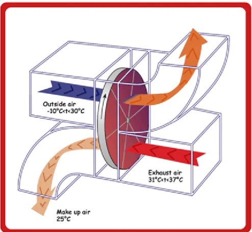
Latent energy recovery is possible, but requires a different recovery system than a runaround coil. Of course, latent energy can be recovered from condensing the flue gasses; however a runaround coil does not transfer moisture from one airstream to the other since it utilizes a heat transfer solution. Enthalpy wheels, or rotary heat exchangers, transfer sensible or sensible and latent energy between the exhaust air and the incoming outside air. Both sensible-only wheels and total energy wheels, sometimes referred to as desiccant wheels, are available (VanGeet, 2006). Desiccant wheels absorb energy, including moisture, and transfers it to the other air stream. Figure 2 below shows how the total energy wheel operates. Careful consideration needs to be taken to be sure that the wheel transfers only moisture and not airborne contaminants (VanGeet, 2006).
Figure 2: Enthalpy Wheel Operation (Miller, 2008)
Energy recovery is a growing concept and continues to expand in the commercial building marketplace.
3.3.
Residential Energy Consumption
According to the 2010 Buildings Energy Data Book, residences consumed 54.5% of the primary energy consumed by buildings in 2010 (D&R International, LTD., 2011). This percentage equates to 22 quadrillion Btu’s of energy. This is equivalent to
792,000,000 tons of coal. This shows an increasing trend from the 2008 levels. With dwindling supplies of natural resources, a large potential for reducing energy
consumption by the end use for a typical residence. As shown, space heating and water heating are the top two energy consumers in a residence. Space heating and cooling – which combined account for 54% of site energy consumption and 42% of primary energy consumption – drive residential energy demand (D&R International, LTD., 2011).
Figure 3: Residential Site Energy Consumption by End Use (D&R International, LTD., 2011)
Data on a typical single-family home is shown below in Table 2. This data is an average of all residences in the United States. As shown the preferred method of space heating, on average, is through a central furnace system. The majority of new residences have central air handling system installed for heating as Table 3 shows. The percentage of furnaces installed has dropped in recent years as the heat pump has been introduced. Heat pumps are versatile, but do not operate at extreme temperatures.
Buildings Energy Data Book: 2.2 Residential Sector Characteristics March 2011
2.2.7 Characteristics of a Typical Single-Family Home (1)
Year Built | Building Equipment Fuel Age (5)
Occupants 3 | Space Heating Natural Gas 12
Floorspace | Water Heating Natural Gas 8
Heated Floorspace (SF) 1,934 | Space Cooling 8
Cooled Floorspace (SF) 1,495 |
Garage 2-Car |
Stories 1 | Appliances Size Age (5)
Foundation Concrete Slab | Refrigerator 19 Cubic Feet 8 Total Rooms (2) 6 | Clothes Dryer
Bedrooms 3 | Clothes Washer
Other Rooms 3 | Range/Oven
Full Bathroom 2 | Microwave Oven
Half Bathroom 0 | Dishwasher
Windows | Color Televisions 3
Area (3) 222 | Ceiling Fans 3
Number (4) 15 | Computer 2
Type Double-Pane | Printer Insulation: Well or Adequate |
Note(s ):
Source(s):EIA, 2005 Res idential Energy Cons um ption Survey: Characteris tics, April 2008, Tables HC 1.1.1, HC1.1.3, HC 2.1, HC 2.2, HC 2.3,
mid 1970s Type
Central Warm-Air Furnace 49 Gallons
Central Air Conditioner Type / Fuel / Number 2-Door Top and Bottom Electric
Top-Loading Electric
1) This is a weighted-average house that has combined characteris tics of the Nation's stock hom es . Although the population of homes with s imilar traits may be few, thes e are likely to be the m os t common. 2) Excludes bathroom s . 3) 11.5% of floors pace. 4) Bas ed on a nominal 3' X 5' window. 5) Years .
Table 2: Characteristics of a Typical-Single-Family Home (D&R International, LTD., 2011)
Buildings Energy Data Book: 2.2 Residential Sector Characteristics March 2011
2.2.8 Presence of Air-Conditioning and Type of Heating System in New Single-Family Homes
Type of Primary Heating System
Warm-Air Hot Water Other or |
Year furnace Heat pump or steam (1) none (2) |
1980 57% 24% 4% 15% | 62% 1985 54% 30% 5% 11% | 70% 1995 66% 25% 5% 4% | 79% 2000 71% 23% 4% 2% | 85% 2005 67% 29% 3% 1% | 89% 2006 63% 33% 3% 2% | 89% 2007 62% 34% 2% 2% | 90% 2008 60% 34% 3% 3% | 89% 2009 56% 37% 3% 4% | 88% Note(s ) Source(s): Total Homes (thousands) Air-Conditioning 957 1,654 1,066 1,242 1,636 1,072 1,218 819 520
1) Includes both air source and geothermal (ground s ource) versions. 2) Includes electric bas eboard, panel, radiant heat, s pace heater, floor or wall furnace, s olar, and other types .
DOC, 2009 Characteristics of New Housing, June 2010, "Type of Heating System Used in New Single-Family Houses Completed" and "Presence of Air-Conditioning in New Single-Family Houses Completed"
Table 3: Presence of Air-Conditioning and Type of Heating System in New Single-Family Homes (D&R International, LTD., 2011)
Heat pumps use an energy input (almost always electricity) to transfer heat from a cold medium (the outside air or ground in the winter) to a warmer medium (the warm air or hot water used to distribute heating in a building). During hot weather, the heat pump
can operate in reverse, thereby cooling the indoor space. In winter, drawing heat from a relatively warm source (such as the ground rather than the outside air) and distributing the heat at the lowest possible temperature can dramatically improve the heat pump efficiency (Levine, et al., 2007). A typical air cooled operation in both cooling and heating are shown below in Figure 4 and Figure 5, respectfully. Air cooled heat pumps are most commonly installed over ground-source heat pumps since the installation cost of the well-field is expensive. A ground source heat pump exchanges energy with the earth rather than the outside air through the use of buried piping.
Figure 5: Air Cooled Heat Pump in Heating Mode
When outdoor temperatures fall below 40°F, a less-efficient panel of electric resistance coils, similar to those in your toaster, kicks in to provide indoor heating. This is why air-source heat pumps aren’t always very efficient for heating in areas with cold winters. Fuel-burning furnaces generally can provide a more economical way to heat homes in cooler U.S. climates (National Renewable Energy Laboratory (NREL), 2001).
Gas fired domestic water heaters operate by passing flue gasses through a flue, which is surrounded by domestic water. Figure 6 below shows a cut-away of a typical non-condensing gas-fired domestic water heater. Electric water heaters are available but are less commonly used when gas is available. As Table 2 above listed, the average single-family residence has a natural-gas fired domestic water heater installed.
Figure 6: Gas Fired Domestic Water Heater Diagram (Guadalupe, 2010)
Since the furnace and water heater combine to consume over 60% of the energy consumed by a typical residence, energy recovery results are best applied to these appliances. This is due to the fact that the largest potential for savings can be realized where the most energy consumption lies.
3.4.
Residential Indirect-Fired Gas Furnace Operation
Natural gas fired furnaces function to heat a supply airstream through the use of a heat exchanger. The heat exchanger keeps combustion gasses separate from the air supplied to the residence. This is why it is referred to as an ‘indirect-fired’ gas furnace. Combustion gas has harmful substances in it that are caustic to breath, so separation of the airstreams is crucial. Natural gas fired residential furnaces are typically an indirect
fired unit. There are applications that use direct-fired furnaces, but these types of furnaces are rarely (if ever) used in a residential application for central air. There are many variations of natural gas indirect-fired furnaces. Figure 7 below is an example of a category I indirect-fired gas furnace. The flue from this furnace is under negative pressure as it uses the stack effect to exhaust combustion gasses to the outdoors. The negative pressure of the flue insures that combustion gasses don’t escape into the residence. There are four vent categories which are classified depending on the furnace components and how the heat is transferred to the supply air stream. These vent
categories are listed in the NFPA standards (National Fire Protection Association, 2002).
• Category I – An appliance that operates with a non-positive vent static
pressure and with a vent gas temperature that avoids excessive condensate production in the vent. This furnace is commonly referred to as a ‘natural draft furnace.’ These units were manufactured before 1992.
• Category II – An appliance that operates with a non-positive vent static
pressure and with a vent gas temperature that may cause excessive condensate production in the vent. This is a variation of the natural draft furnace.
• Category III – An appliance that operates with a positive vent static
pressure and with a vent gas temperature that avoids excessive condensate production in the vent. This furnace is commonly referred to as an
‘induced-draft non-condensing furnace.’
• Category IV – An appliance that operates with a positive vent static
pressure and with a vent gas temperature that may cause excessive condensate production in the vent. This furnace is commonly referred to as an ‘induced-draft condensing furnace.’
Flue gas is very corrosive by nature. This is due to the fact that most conventional fuels contain small amounts of sulfur, which is oxidized to sulfur dioxide (SO2) or sulfur
trioxide (SO3) during combustion, and the noncombustible substances such as mineral
mater (ash) , water, and inert gas (2009 ASHRAE Fundamentals, 2009). When sulfur trioxide comes in the presence of water vapor, sulfuric acid forms. This is shown in Equation 1.
+ ⇔
+ ⇔
Equation 1: Flue Gas Condensation Chemical Reaction
Galvanized steel is commonly used for venting a non-condensing furnace (category I and III). When galvanized steel comes into contact with an acid, the zinc plating deteriorates from a chemical reaction with the sulfuric acid. After the zinc coating (sacrificial anode) is depleted, the exposed steel remains unprotected. The exposed steel will begin to corrode in the presence of an oxidizing agent, such as oxygen. For this reason, careful consideration needs to be taken in the selection of materials for natural gas fired furnaces. The material used for the heat exchanger is just as crucial.
Category III vents are used on non-condensing induced-draft furnaces. When this type of furnace operates it uses a fan to induce air into the heat exchanger where
combustion occurs. Typical category III furnaces will use a horizontal venturi-type burner. Fuel exiting from the fuel gas orifice enters one end of the venturi as a jet. This induces the primary combustion air into the venturi where turbulent mixing occurs. About 60% of the air required for complete combustion (stoichiometric air) is drawn in by this process. An inner combustion cone sits at the outlet end of the venturi. The remaining or secondary combustion air is drawn into the flame zone at the outlet end of the venturi by the combined action of the induced draft from the fan-assist and the buoyancy of the flue gasses. Here the air mixes with the unburned fuel and products of combustion from the inner combustion zone. The combustion is controlled by diffusion and turbulent mixing, resulting in a secondary burn out region that stretches well into the
heat exchanger (Fleck, Arnold, Ackerman, Dale, Klaczek, & Wilson, 2009). Figure 8 shows a single venturi-type burner. Furnaces have multiple burners installed for operation typically.
Figure 8: Venturi-type Burner Schematic (Fleck, Arnold, Ackerman, Dale, Klaczek, & Wilson, 2009)
A combustion process is considered complete if all the carbon in the fuel burns to CO2,
all the hydrogen burns to H2O and all the sulfur burns to SO2 (Cengel & Boles, 2006).
The three fundamental chemical reactions that occur during the combustion of a hydrocarbon fuel are shown below (2009 ASHRAE Fundamentals, 2009). Further discussion of the combustion process is found in the Furnace Combustion Analysis section.
+ →
+ →
Equation 2: Hydrocarbon Combustion Process Fundamental Reactions
Heat exchangers for induced-draft furnaces are made out of aluminized steel. Although aluminized steel has better corrosion properties than galvanized steel, it is still susceptible to oxidation (corrosion). The vent on this type of furnace (category III) can be
galvanized steel since condensation is not likely in the flue piping.
A condensing gas furnace (high-efficiency) is much like an induced-draft furnace in that the flue is under positive pressure from the fan that aids in combustion. Burners are typically venturi-style as well. The main difference is that a condensing gas furnace has a series of heat exchangers. A second heat exchanger is located downstream of the standard aluminized steel exchanger. The second exchanger is typically made out of stainless steel or some material that is corrosion resistant. In the secondary heat exchanger, more energy is transferred from the combustion gasses to the point that condensation starts to precipitate out of the combustion gasses. In a condensing gas furnace, the most corrosive conditions exist at the leading edge of the condensing region, especially areas that experience evaporation during each cycle (Stickford, Talbert, Hindin, & Locklin, 1988). Draining condensate retards the concentration of acids on system surfaces; regions from which condensate partially or completely drains away before evaporation are less severely attacked than regions from which condensate does not drain before evaporation (2009 ASHRAE Fundamentals, 2009). As shown in
130°F-150°F depending on the amount of excess air applied to the combustion process. In general, any natural gas flue gas temperature below 130°F will start to condense.
Figure 9: Theoretical Dew Points of Combustion Products of Industrial Fuels (2009 ASHRAE Fundamentals, 2009)
Efficiency of space heating systems for residential and commercial buildings are usually expressed in terms of the annual fuel utilization efficiency, or AFUE, which accounts for the combustion efficiency as well as other losses such as heat losses to unheated areas and start-up and cool-down losses (Cengel & Boles, 2006). Over the years, the AFUE ratings of gas-fired furnaces have increased. The minimum allowed AFUE rating for a non-condensing fossil-fueled, warm-air furnace is 78%; the minimum rating for a fossil-fueled boiler is 80%; and the minimum rating for a gas-fueled steam
boiler is 75% (U.S. Department of Energy, 2011). The following are typical AFUE ratings for different residential heating and ventilation equipment.
• Old, low-efficiency heating systems:
→ Natural draft venting → 68%-72% AFUE
• Mid-efficiency heating systems:
→ Induced-draft combustion → Positive pressure venting → 80%-83% AFUE
• High-efficiency heating systems:
→ Condensing flue gasses in a second heat exchanger for extra efficiency → 90%-97% AFUE (U.S. Department of Energy, 2011)
The annual fuel utilization efficiency can be determined by following the testing procedure found in ASHRAE Standard 103 (Method of testing for annual fuel utilization).
3.5.
Options for Residential Gas Fired Furnace Energy Recovery
Energy recovery from an indirect-fired gas furnace lies in the recovery of energy from flue gasses. High efficiency condensing gas furnaces take advantage of the extra energy in the flue gasses by having a secondary condensing heat exchanger, as previously discussed. While high efficiency furnaces take advantage of the excess energy, not many residences in the United States have high efficiency furnaces installed. As shown in Table 4,
in 2006 over half of the gas-fired furnaces shipped in the United States were between 75%-88% efficient. The AFUE of most new heating systems is about 85%, although the AFUE of some old heating systems is under 60% (Cengel & Boles, 2006).
Buildings Energy Data Book: 5.3 Heating, Cooling, and Ventilation Equipment March 2011
5.3.2 Residential Furnace Efficiencies (Percent of Units Shipped) (1)
AFUE Range 1985 AFUE Range 2006 AFUE Range 1985
Below 65% 15% 75% to 88% 64% Below 75% 10%
65% to 71% 44% 88% or More 36% 75% to 80% 56%
71% to 80% 10% Total 100% More Than 80% 35%
80% to 86% 19% Total 100%
More than 86% 12%
Total 100%
Average shipped in 1985 (2): 74% AFUE Average shipped in 1985 (2): 79% AFUE Average shipped in 1995: 84% AFUE Average shipped in 1995: 81% AFUE
Best Available in 1981: 85% AFUE Best Available in 1981: 85% AFUE
Best Available in 2007: 97% AFUE Best Available in 2007: 95% AFUE
Note(s):
Source(s):
Gas-Fired Oil-Fired
1) Federal appliance standards effective Jan. 1, 1992, require a minimum of 78% AFUE for furnaces. 3) Includes boilers .
GAMA's Internet Home Page for 2006 AFUE ranges; GAMA New s, Feb. 24, 1987, for 1985 AFUE ranges; LBNL for average shipped AFUE; GAMA, Consumer's Directory of Certified Efficiency Ratings, May 2004, p. 12 and 72-73 f or 2004 best-available AFUEs; GAMA Consumer's Directory of Certif ied Ef ficiency Ratings for Heating and Water Heating Equipment, May 2007; GAMA Tax Credit Eligible Equipment: Gas- and Oil-Fired Furnaces 95% AFUE or Greater, May 2007; and GAMA AFUE press release 2006: U.S. shipments of gas w arm-air central furnaces.
Table 4: Residential Furnace Efficiencies (Percent of Units Shipped) (D&R International, LTD., 2011)
A higher AFUE rating means that more energy is transferred to the supply air stream. For example, a 90% AFUE 100Mbh furnace transfers 90Mbh of useful energy to the supply air stream during the operation of the furnace. This leaves 10Mbh to be lost during the operation. A majority of these losses are in the flue gas as it exits the building. There is a potential for recovering all of this lost energy if the recovery method is efficient. Government
regulations have placed a minimum of a 78% AFUE rating for gas-fired furnaces in residences, as previously mentioned. Depending on the
efficiency of the furnace, a substantial amount of energy is being lost during the heating of a residence. Since a majority of waste energy is found in the
hot flue gasses, this is where the greatest possibility for energy recovery lies. The recovered energy from the flue gasses can be used for many purposes depending on the recovery method.
One option would be to heat the outdoor air (ventilation air) being brought into the home. However, not many homes have outdoor air
introduced to the furnace directly since operable windows bring in ventilation air that meets the residential building code (IRC 2009). This will create a difficulty in treating the ventilation air since it is not coming into the residence from one location.
Another option would be to use the recovered energy to maintain water temperatures inside the hot water heater. This application would decrease gas or electrical costs to operate the hot water heater. Modification of the domestic water heater would be required to integrate a heat transfer coil inside the heater in order to transfer the energy. UL listed equipment would no longer be UL listed with these modifications, which creates a drawback to the proposed system.
The application chosen as the most attractive is to use the recovered waste energy to provide a radiant heated slab in the winter. The recovered energy will be used to heat the driveway and sidewalk concrete slabs to melt snow during winter storms in the Midwest. This offers an attractive benefit to homeowners as well as a payback that may fit inside the proposed timeline for a homeowner. Although a radiant heated driveway is more of a novelty
than a necessity, it provides many benefits and savings. This will be discussed further in the Economic Analysis section.
3.6.
Proposed Energy Recovery System
As discussed, space heating accounts for nearly 45% of residential energy use (see Figure 3). The opportunity for energy recovery in a residence is best applied to the largest source of energy consumption. For this reason an energy recovery system on a gas fired furnace offers great possibilities. Since most wasted energy from a residential furnace is in the flue gasses, energy recovery should be applied to the flue gasses. The installed energy recovery system shall not prohibit proper operation of the furnace. Flue gasses are poisonous to occupants of the home and need an unrestricted path to the outdoors. Careful consideration needs to be taken in the materials used to recover the energy from the flue gasses. Since condensing flue gasses is highly likely, special
considerations need to be made as to what materials are selected for the recovery system. The recovered energy will be transferred to an intermediate heat transfer fluid, consisting of water and a glycol additive. A radiant heating system for a driveway will be the application for the recovered waste energy. A radiant heat system provides multiple benefits.
First is the reduction in physical work needed for snow removal. Snow removal creates an inconvenience for home owners. In the city of Omaha it is a requirement to clear the public sidewalks. In addition to obeying the law, snow can cause liability concerns should someone slip and be injured on your property. Most people will agree that the last thing they want to do on a blustery-cold day is crawl out of bed, typically early in the morning, to scoop snow before they head to work. The task of snow removal is such that
many people avoid it, even if it incurs a financial cost. Private contractors make a living on snow removal services during the winter season. This is no surprise. It proves that there is a substantial benefit to the home owner to pay for these services.
The second benefit of a radiant heat system is that the snow disappears on its own without costing extra money. There is no physical labor involved or capital expense to remove the snow. Payback is an important concept with investments. If the investment doesn’t pay for itself or have a reasonable return on investment (ROI) it is not an
attractive investment. In the Midwest it is not uncommon to pay $400-600 per winter for driveway cleaning by a private contractor (Sharp, 2012). If a furnace energy recovery system can be utilized as a radiant snowmelt system, the savings each season are substantial and can yield a short payback period depending on the cost of the energy recovery system.
The radiant heating system will consist or a runaround coil system. The pump will circulate a glycol solution through the radiant system outdoors and through an energy recovery coil indoors. The indoor recovery coil will extract excess heat from the furnace flue gasses as they travel through the flue. A revised flue system will be included in the considerations. The system shall extract as much heat from the gasses as necessary to provide a functioning snow melt system.
3.7.
Economic Analysis
Unfortunately, many decisions in the world are driven by financial costs. Investments need to make a substantial impact so that the money is not wasted. The capital investment should produce outcomes that save money and produce a short
payback. The recovery system has little maintenance to be performed but should be considered in the payback analysis.
3.7.1.
Analysis
Many people in the United States will own multiple houses in their lifetime so it is important to consider how long people typically own the same home. According to the 2010 American Community Survey completed by the U.S. Census Bureau, 61.6% of house owners in the state of Nebraska moved into their house in the year 2000 or later while only 17.6% moved into their house from 1990-1999 (U.S. Census Bureau, 2010). These statistics show that the vast majority of home owners live in one home for 12 years or less on average. For residential capital improvement to be beneficial to an owner the payback will need to be completed in less than 12 years.
A construction cost has been estimated per square foot of treated concrete slab. Each residence has a unique area that would be heated by such a system. Assuming an average snow removal cost of $100 per snowfall (industry average charge) will aid in the payback analysis. Costs for a hydronic radiant heat system range from $6-$12 per square foot of coverage (Anderson Radiant Heating, 2006). This price is the total installed cost, including a boiler to heat the glycol solution. Using the median price per square foot ($9/ft2) a typical two-car driveway that is 35 feet long (~960 sq. ft.) would cost $8,640 to install a hydronic heating system. For a radiant system of this price to pay back in 12 years an average yearly cost for snow removal would be $720. This would yield a payback of 12 years. According to the National Oceanic and Atmospheric
Administration, Omaha Nebraska averages 8.8 days per year where snowfall of at least 1” occurred (National Oceanic and Atmospheric Administration, 2010) (Current Results:
Research News & Science Facts, 2012). These average days of snow would yield a yearly cost of $880 per year at the stated rates.
Maintenance on the system would be negligible. The heat transfer solution wouldn’t need to be drained or replaced very often on a closed system. To be conservative, a life maintenance cost for fluids has been estimated at $75. Of course the circulation pump could fail but is very unlikely given the yearly run duration. These pumps are only run when called upon and will not see many hours of operation each year. A conservative estimate of replacing the pump once every 12 years has been considered. The cost of the circulation pump used in this research was $80.
The cost of electricity in the city of Omaha Nebraska in the winter is listed below.
• $0.0964/kwh for the first 100 kwh • $0.0834/kwh for the next 900 kwh • $0.0579/kwh for the next 1000 kwh
The circulation pump utilized for this study was rated to 200 watts. The pump is
considered to run for the entire day that the snow occurs. The power usage per snow day is below.
= 200 ∗ 24 " ∗ 8.8 $% = 42,240 − ℎ" 42.24 )ℎ
Table 5: Circulation Pump Electricity Cost (OPPD, 2012)
$0.0964/kwh $0.0834/kwh $0.0579/kwh
Yearly Cost $4.07 $3.52 $2.45
As Table 5 above shows, the cost to run the circulation pump is negligible.
Considering the above analysis, a simple payback calculation has been shown below in Equation 3. As the calculation shows, there is a favorable payback considering the assumptions stated above.
*+, %-.) =/01 + ,*0 ∗ 2 + 3*4 5*000.
6*0 , 2
*+, %-.) =$8,640 + $4.07: + $155
$880 *+, %-.) = ~10 2
Equation 3: Simple Payback
Finally, Figure 10 shows the simple payback analysis. This analysis considers the maintenance cost as being divided up equally among the expected 12 year life of the pump and glycol solution. A typical contractor bill for snow removal in Omaha, Nebraska is provided in Appendix B.
Figure 10: Simple Payback Graph
CHAPTER 4:
Initial Analytical Analysis
4.1.
Radiant Heated Driveway Analysis
Analyzing a radiant snow-melting system has many variables to consider. Among these variables are (1) rate of snowfall, (2) snowfall-coincident air dry-bulb temperature, (3) humidity, (4) wind speed near the heated surface, and (5) apparent sky temperature (ASHRAE, 2011). By performing a heat balance on the radiant slab under a steady-state condition, a required heat flux for the concrete surface can be calculated. Equations listed below are sourced from the ASHRAE applications handbook.
= = > + ?+ @AB+ C
Equation 4: Radiant Slab Energy Balance
Where; 0 2 4 6 8 10 12 14 1 2 3 4 5 6 7 8 9 10 11 12 13 T h o u sa n d s o f d o ll a rs Years Cost Savings
= = ℎ 4"D "*1 0 − +*0 "4.,ℎ ∙ 4-" > = 0*- ℎ 4"D,ℎ ∙ 4-" ? = 0 ℎ 4"D,ℎ ∙ 4-" @A = @F @G = 0 H @ I @ = 0 − 4 *, 1*+0*0 B = .06.*6 01 1**6 ℎ 4"D 4+ 0 − 4 "4.,ℎ ∙ 4J" C = ℎ 4"D 4 6,*0,ℎ ∙ 4J"
The sensible and latent heat flux variables are the energy required to raise the temperature of the falling snow, raise the temperature of the liquid film layer on the concrete, and to melt the snow. The snow-free area ratio is the ratio of concrete with no snow coverage to the total concrete surface area. When snow has covered the surface of the concrete it acts as an insulating layer preventing heat transfer from occurring. As the snow covered area increases, the amount of energy loss (transfer) from the concrete slab decreases.
Below is the equation for sensible heat flux qs.
> = KLMGCAN.O,PQC>− M + .O,LMGCARF− >ST/.V
Equation 5: Sensible Heat Flux Equation
Where;
.O,LMGCA = ,.*4*. ℎ 4 ,- ∙ ℉-" = 04 "*60,*0 ℎ M = +-*0 +," .*0.*10 *ℎ 04, ℉ F= *"*1 4*+ +,", ℉ (usually taken as 33°F) > = +*0 +,", ℉ KLMGCA= 10*% 4 ,4 -.V = 12 *04
The heat flux of evaporation is the energy required to melt the snow. This value is calculated using Equation 6.
? = KLMGCAℎPF/.V
Equation 6: Heat Flux to Melt Snow
Where;
ℎPF = ℎ 4 4"*0 4 0,J"
3-As mentioned, the concrete slab will have heat losses associated with it if it is not being insulated by snow cover. The convective and radiative heat losses from the snow-free surfaces are described using Equation 7.
Equation 7: Convective and Radiative Heat Loss Where; ℎQ = .06.*0 ℎ 04 .44*.*0 4 "-"0 4,ℎ ∙ 4J"∙ ℉ IF= *"*1 4*+ +,", °] I[\ = +0 1*0 +," 4 ""01*0, °] Y = 40 − J^+00 .00 =0.1712 D 10_`ℎ ∙ 4J" ∙ °] Z> = +*0. 4 "4., 1*+0*0
The convection heat transfer coefficient over a horizontal surface involvers turbulent airflow and uses a special heat transfer equation to calculate this coefficient. This equation is listed below in Equation 8.
ℎQ = 0.037 b)MPA3 c ]de.`V/
Equation 8: Convective Heat Transfer Coefficient for Turbulent Flow over a Horizontal Plane
Where;
)MPA = ℎ+ .01".*6*% 4 * M,ℎ ∙ 4J" ∙ 4∙ ℉
3 = .ℎ.**. 0ℎ 4 - *0 1*.*0 4 *01, 4 = 01 0"+- 4 *, )0 Pr = 0.7
]d = ]%01 0"+- -1 0 .ℎ.**. 0ℎ 3
]d = ih3 MPA.
Equation 9: Reynolds Number Based on Characteristic Length
Where; h = 1*0 *01 ,1 0 - "4., +,ℎ iMPA = )*0+*. 6*.*% 4 *,4 ℎ . = 5280 +*4
The mean radiant temperature TMR is calculated using Equation 10.
I[\ = NIQj=kl H>Q+ I>mn QjCMA 1 − H>QTV/
Equation 10: Mean Radiant Temperature
Where;
H>Q = 4.*0 4 1**0 D.ℎ0 ℎ .." -0 - 01 ."1
IQj=kl = +," 4 ."1, °]
I>mn QjCMA = +," 4 . )%, °]
The equivalent temperature of a clear sky is given by a curve fit of data in Ramsey et al. (1982).
I>mn QjCMA = IM− 1.99036 D 10 − 7.562IM+ 7.407 D 10_ IM− 56.325p + 26.25p
Where;
IM = +-*0 +,", °]
p =relative humidity of air at elevation which typical weather measurements are made Now that the convection heat transfer and radiative heat flux has equations to be calculated, the final term to evaluate is the evaporative heat flux from evaporating the film later of water on the surface of the concrete. The heat flux required to evaporate water from the wet concrete surface is equated using Equation 12.
C = KlAn MPAℎ?RF− MSℎFq
Equation 12: Evaporative Heat Flux Required to Evaporate Water from Radiant Slab
Where; ℎ? = + 04 .44*.*0,4ℎ M = ℎ"+*1*% * 4 +-*0 *,--rMO=A MPA F= ℎ"+*1*% * 4 "1 * 4*+ "4. +,,--rMO=A MPA ℎFq = ℎ 4 6,*^*0,J" -KlAn MPA = 10*% 4 1% *,4
-In order to calculate the mass transfer coefficient, the convective heat transfer coefficient is needed. Using Equation 13 the mass transfer coefficient can be calculated.
ℎ? = b.c
/ ℎ
Q
KlAn MPA.O,MPA
Equation 13: Mass Transfer Coefficient
Where;
= 01 0"+- 4 * . = .ℎ+*1 0"+-
Humidity ratios in the atmosphere and at the surface of the water film are
calculated using the standard psychometric relation given in the following equation (from Chapter 1 of the 2009 ASHRAE Handbook – Fundamentals). This equation is listed below.
= b, − ,,r
rc
Equation 14: Humidity Ratio
Where;
,r = ,* ," 4 6,, ,*
, = +,ℎ*. ,", ,*
Since atmospheric pressure varies depending on the location on earth and its relative altitude, Equation 15 adjusts the atmospheric pressure based on location’s altitude.
, = ,>Glb1 −@Is =c
t.ut
Equation 15: Atmospheric Pressure Adjustment Based on Altitude
Where;
,>Gl = 011 +,ℎ*. ,", ,*
@ = 0.00356°]4
^ = *"1 4 ℎ .*0 -6 6, 4
I= = 518.7°]
Using these equations, the heat flux required at the radiant slab surface can be calculated.
4.2.
Heated Driveway Calculation
The list of variables and their specific values are found below in Table 6. The variables describe a day where the ambient temperature is 30°F with a 17mph wind speed. The snowfall rate is described as 1” of snow per hour.
vw,xvy = z. {| } ∙ °}~ vw,~y= . z } ∙ °}~
~y = . { ~} = 0.167 ℎ ~1" 4 0 ℎ*0
~ = z ℉ (dew point temp = 14℉) F= 33 ℉
~= ℉ ℎ PF = 143.3 J" - = w 6 MPA= 0.49 4 ℎ
x= z. z ∙ ~~ ∙ ~∙ ℉ 3 = 6 4 = z. . = z. x= z. z ~} .O,MPA = 0.24 - ∙ ℉J" = z. zz z }}w x F = 0.00393 -rMO=A -MPA = z. | ℎ Fq = 1075 J"
-Table 6: Radiant Slab Calculation Variables
With the equations listed in the previous section, a calculated energy flux can be
calculated to determine the required heat for the radiant system to be feasible. In order to apply Equation 4, various intermediate terms need to be calculated. The steps to
calculate the energy required for the radiant slab are show below.
Applying Equation 5 below, we find the sensible heat flux. This is the required heat to bring the snow temperature up to 32°F. Using Equation 6 will calculate the heat flux required to melt the snow on the concrete slab. This is shown below.
> = 62.4 D 0.16712 0.4932 − 30 + 1.033 − 32 = 1.72 ℎ ∙ 4J"
? = 62.4 D 0.16712 D 143.3 = 124.4 ℎ ∙ 4J"
The next term to be calculated is the heat loss from the slab surface because of convective and radiative heat transfer. This number is dependent on the snow-free area ratio. This calculation will be completed using various snow-free area ratios in order to simulate multiple conditions. If the radiant slab system was neglected to be turned on,
the snow would accumulate before the system was started. This would represent a snow-free area ratio of 0. If the radiant system was running from the start, then a snow-free area ratio of 1 would be used. Before the heat losses from the slab can be calculated using Equation 7, the convective heat transfer coefficient must be calculated, which requires Reynolds number from Equation 9.
]d = 17 D 60.49 D 5280 = 1.09 D 10u
ℎQ = 0.037 b0.01356 c 1.09 D 10ue.`0.7V/ = 4.99ℎ ∙ 4J" ∙ ℉
B = 4.9932 − 30 + 0.1712 D 10_`0.9492.67 − 489.67 = 12.17 ℎ ∙ 4J"
A couple final intermediate terms are required to apply the overall energy balance. One of those terms is the mass transfer coefficient which is calculated using Equation 13.
ℎ? = b0.70.6c
4.99
0.081 D 0.24 = 284.5 4ℎ
The final term to be calculated before the application of the energy balance is the evaporative heat flux from the surface of the concrete. This value represents the heat required to evaporate the water from the wet surface.
C = 0.081 D 284.50.00393 − 0.00160 D 1075 = 57.7ℎ ∙ 4J"
Finally, Equation 4 can be applied. Table 7 lists the heat required for a 10’ x 6’ slab.
= = 1.72 + 124.4 + @A12.17 + 57.7 = . z (no snow cover
before startup)
= |. z ∙ ~~ = . ~
= z. (half snow cover
before startup)
== 161.0 ℎ ∙ 4J" ¡ = 9.6 )J"ℎ
= z (full snow cover
before startup)
== 126.1 ℎ ∙ 4J" ¡ = 7.6 )J"ℎ
Table 7: Heat Flux Required at Snow-Melting Surface
As shown in the calculations, a bulk of the heat required is due to the evaporative energy required to evaporate water from the wet radiant surface. This is largely due to the wind speed of 17mph. Various conditions will adjust what is required of the radiant system to operate properly. Diversity needs to be considered in this calculation since there is a low possibility that the coldest day with the largest wind speeds will fall on the same day and time that the largest snowfall rate per hour occurs. Another important note is that the heat required for the radiant slab calculated above does not take into account the heat losses at edges. Edge loss is dependent on the slab construction and how it was insulated. Adlam (1950) demonstrated that these back and edge losses may vary from 4 to 50%, depending on factors such as slab construction, operating temperature, ground temperature, and back and edge insulation and exposure (ASHRAE, 2011).
4.3.
Furnace Combustion Analysis
The combustion process at the furnace will determine how much heat is
obtainable. The amount of heat released during the combustion process depends heavily upon the amount of natural gas that is combusted during the process. As discussed, the