www.sentera.eu
MIW-SEPS8-24-40-EN-000 - 06 / 12 / 2019 2 - 7
Table of contents
SAFETY AND PRECAUTIONS
3
PRODUCT DESCRIPTION
4
ARTICLE CODES
4
INTENDED AREA OF USE
4
TECHNICAL DATA
4
STANDARDS 4
WIRING AND CONNECTIONS
5
MOUNTING INSTRUCTIONS IN STEPS
5
VERIFICATION OF INSTALLATION
7
TRANSPORT AND STORAGE
7
WARRANTY AND RESTRICTIONS
7
www.sentera.eu
MIW-SEPS8-24-40-EN-000 - 06 / 12 / 2019 3 - 7
back to the table of contents
SAFETY AND PRECAUTIONS
Read all the information, the datasheet, mounting and operating instructions and study the wiring and connection diagram before working with the product. For personal and equipment safety, and for optimum product performance, make sure you entirely understand the contents before installing, using, or maintaining this product.
For safety and licensing (CE) reasons, unauthorised conversion and / or modifications of the product are inadmissible.
The product should not be exposed to abnormal conditions, such as: extreme temperatures, direct sunlight or vibrations. Long-term exposure to chemical vapours in high concentration can affect the product performance. Make sure the work environment is as dry as possible; avoid condensation.
All installations shall comply with local health and safety regulations and local electrical standards and approved codes. This product can only be installed by an engineer or a technician who has expert knowledge of the product and safety precautions.
Avoid contacts with energised electrical parts; always treat the product as if it is live. Always disconnect the power supply before connecting, servicing or repairing the product.
Always verify that you apply appropriate power supply to the product and use appropriate wire size and characteristics. Make sure that all the screws and nuts are well tightened and fuses (if any) are fitted well.
Recycling of equipment and packaging should be taken into consideration and these should be disposed of in accordance with local and national legislation / regulations.
In case there are any questions that are not answered, please contact your technical support or consult a professional.
www.sentera.eu
MIW-SEPS8-24-40-EN-000 - 06 / 12 / 2019 4 - 7
back to the table of contents
PRODUCT DESCRIPTION
SEPS8-24/40 are compact 24 VDC / 40 W switch-mode power supply modules specially designed for harsh climate conditions. They are Power over Modbus compatible and have a wide supply voltage range.
ARTICLE CODES
Code Input voltage
SEPS8-24/40 85—264 VAC / 50—60 Hz
INTENDED AREA OF USE
■ Supply for 24 VDC articles used in harsh conditions
TECHNICAL DATA
■ Input voltage: 85—264 VAC / 50—60 Hz
■ Output voltage: 24 VDC
■ Output current rating Imax 1,67 A
■ Protections: overvoltage and overload (hiccup mode) ■ Power ON green LED indication
■ Protection class: IP 65
■ Enclosure: ABS plastic, colour: grey (RAL7035) ■ Storage temperature: -40—85 °C
■ Operating ambient conditions:
►temperature range: -30—40 °C
►rel. humidity: 20—90 % rH (non-condensing)
STANDARDS
■ Low Voltage Directive 2014/35/EC
■ EMC Directive 2014/30/EC: Emission Standards: EN55022 (CISPR22) Class
B and EN61000-3-2,3; Immunity standards: EN61000-4-2,3,4,5,6,8,11 and EN55024, Heavy industry Level criteria A
■ WEEE Directive 2012/19/EC
www.sentera.eu
MIW-SEPS8-24-40-EN-000 - 06 / 12 / 2019 5 - 7
back to the table of contents
WIRING AND CONNECTIONS
Terminal block L Supply voltage, line: 85—264 VAC / 50—60 Hz
N Supply voltage, neutral: 85—264 VAC / 50—60 Hz
+24 V Output voltage connection (24 VDC)
GND Ground for output voltage connection
RJ45 /B A GND 24 VDC8 mm 8 mm 8 mm 8 mm
RJ45
1 2 3 4 5 6 7 8 1 2 3 4 5 6 7 8 24 VDC Output voltage 24 VDC GND GroundA Modbus RTU communication, signal A
/B Modbus RTU communication, signal /B
MOUNTING INSTRUCTIONS IN STEPS
Before you start mounting the SEPS8 switch-mode power supply module, read carefully “Safety and Precautions”. Choose a smooth surface for an installation location (a wall, panel, etc.) and follow these steps:
1. Unscrew the front cover of the enclosure to remove it.
2. Fix the enclosure onto the surface by means of suitable fasteners while adhering to the mounting dimensions shown in Fig. 1Mounting dimensions and the correct mounting position shown in Fig. 2Mounting position.
Fig. 1 Mounting dimensions Fig. 2 Mounting position
108,5 mm 71 mm 4x 4,2 83,8 mm 166 mm 59 mm Correct Incorrect
www.sentera.eu
MIW-SEPS8-24-40-EN-000 - 06 / 12 / 2019 6 - 7
back to the table of contents
3. Insert the cable though the cable gland.
4. Connect the mains supply to L and N (see Fig. 3) adhering to the information in section “Wiring and connections” above
Fig. 3 Wiring diagram
Supply voltage 85—264 VAC / 50—60 Hz Output voltage 24 VDC Output voltage 24 VDC
6. If you will use the RJ45 socket for output voltage connection, first insert the cable through the cable gland, then crimp and plug it in. If you will use the terminal block, insert the cable through the gland and do the wiring as indicated in the “Wiring and connections” section and Fig. 3 above to connect the device you wish to supply via SEPS8. See Example 1Connection via RJ45 connector
and Example 2 Connections via terminal block below for suitable application
examples.
Example 1: Connections via RJ45 connectors Example 2: Connections via terminal block SEPS8 DPS-M-XK0-2 24 VDC Supply voltage 85—264 VAC / 50—60 Hz SEPS8 24 VDC HPS-XK0-2 Supply voltage 85—264 VAC / 50—60 Hz
7. Put back the front cover and screw it.
www.sentera.eu
MIW-SEPS8-24-40-EN-000 - 06 / 12 / 2019 7 - 7
back to the table of contents
VERIFICATION OF INSTALLATION
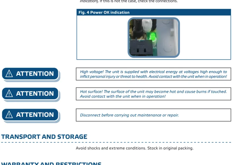
1. After switching on the power supply, the green LED should be ON (see Fig. 4Power OK
indication). If this is not the case, check the connections.
Fig. 4 Power OK indication
ATTENTION
High voltage! The unit is supplied with electrical energy at voltages high enough to inflict personal injury or threat to health. Avoid contact with the unit when in operation!ATTENTION
Hot surface! The surface of the unit may become hot and cause burns if touched. Avoid contact with the unit when in operation!ATTENTION
Disconnect before carrying out maintenance or repair.TRANSPORT AND STORAGE
Avoid shocks and extreme conditions. Stock in original packing.
WARRANTY AND RESTRICTIONS
Two years from the delivery date against defects in manufacturing. Any modifications or alterations to the product after the date of publication relieve the manufacturer of any responsibilities. The manufacturer bears no responsibility for any misprints or mistakes in this data.
MAINTENANCE
In normal conditions this product is maintenance-free. If soiled, clean with a dry or damp cloth. In case of heavy pollution, clean with a non-aggressive product. In these circumstances the unit should be disconnected from the supply. Pay attention that no fluids enter the unit. Only reconnect it to the supply when it is completely dry.