DC Grid Discriminating Protection
Rui Sérgio Senra Barbosa Dantas
School of Engineering
Cardiff University
A thesis submitted for the degree of
Doctor of Philosophy (PhD)
To my loving parents, António and Benvinda, for their encouraging words and hard work which supported my education in multiple ways.
Abstract
High-voltage direct current (HVDC) has been proven an affordable and technically capable solution to bring vast amounts of power over long distances, though overhead lines, un-derground or undersea cables. As a result, a large number of point-to-point HVDC links appeared in several locations over the last decades. The technological step currently going on is the connection of point-to-point links to form a multi-terminal dc (MTDC) grid, a configuration that would bring several advantages. The construction of MTDC grids faces a few technical challenges, where the most notorious one might be dc grid protection.
This thesis presents protection strategies for MTDC grids equipped with different dc fault clearance and isolation devices. These include ac circuit breakers (ACCBs), converters with fault blocking (FB) capability, dc circuit breakers (DCCBs) and fast dc disconnectors (only for isolation purposes). Each of these strategies in presented in a chapter, where the steps of the protection strategy are described and overvoltage suppression methods are proposed. The protection strategies include dc fault detection and dc fault discrimination algorithms. In literature, extensive research is available regarding dc fault discrimination, potentially the "hottest" topic in dc protection. In this thesis, discrimination algorithms are proposed being those based on analysis of local currents and voltages. Thus, link communication channels are not required, which reduces the overall decision-making time.
The performance of the developed protection strategies is tested in PSCAD/EMTDC environment. DC faults are applied on two MTDC grids, including a 4-terminal meshed grid and the CIGRE 11-terminal dc grid. The main outcomes of this thesis include the discriminative fault criteria and the tailored protection strategies for dc grids equipped with either ACCBs, FB converters or DCCBs as main fault current clearance devices.
Acknowledgements
The development of this piece of work was only possible thanks to the support of extraordi-nary people.
Firstly and foremost, I would like to express my gratitude to my academic supervisors at Cardiff University, Professor Jun Liang and Dr Carlos E. Ugalde-Loo. I received guidance, advices and tips, at academic and personal levels,that helped me to deliver a much improved thesis (and in a timely manner).
Secondly, I would like to thank to my industrial supervisor at GE Grid’s Solutions, Professor Carl Barker. The challenges posed along the way developed my technical and communication skills, and turned myself in a much better engineer. Dr Andrzej Adamczyk and Robert Whitehouse are also acknowledged for their outstanding technical advice. The author is very grateful to GE’s Grid Solutions for the technical and financial support provided for this research project.
Thirdly, a number of friends at Cardiff made this journey an amazing time of my life. Special thanks to Sedef, Sathsara, Marc and Leo. Many other names are missing on this page, but not in my heart - you know who you are. Thank you all very much. We will keep in touch.
Lastly, part of my personal life is based on an wonderful family. I am immensely happy of having a family that supported, motivated and encouraged me in every possible way. To my parents, my sister and my brothers, their partners, and my nieces, I thank you all for bringing a balance to my life and smiles to my face.
"We must learn to live together as brothers or perish together as fools."
"Devemos aprender a viver juntos como irmãos ou perecer juntos como tolos."
"Ya karde¸s gibi birlikte ya¸sayaca˘gız ya da aptallar gibi birlikte Yok olaca˘gız."1
Martin Luther King Jr.
Table of contents
Declaration ii
Dedication v
Abstract vii
Acknowledgements ix
List of abbreviations xix
List of figures xxi
List of tables xxvii
1 Introduction 1
1.1 Background and Motivation . . . 1
1.2 Research Objectives . . . 5 1.3 Thesis Structure . . . 7 1.4 List of Publications . . . 9 1.5 List of Contributions . . . 9 1.6 Project Participation . . . 11 2 Literature Review 13 2.1 Introduction . . . 13 2.2 Challenges of DC Protection . . . 14
2.2.1 Requirements for Protection . . . 15
2.2.2 Grid Behavior Under a DC Fault . . . 15
2.3 Fault Detection and Discrimination Methods . . . 17
2.3.1 Current and Voltage Magnitude-Based Methods . . . 18
2.3.3 Unit Protection Methods . . . 21
2.3.4 Signal Processing and Other Methods . . . 23
2.3.5 Comparison and Discussion . . . 24
2.4 Converters, Fault Clearance and Isolation Devices . . . 25
2.4.1 Converters for HVDC grids . . . 26
2.4.2 DC Circuit Breakers (DCCBs) . . . 29
2.4.3 AC Circuit Breakers (ACCBs) . . . 30
2.4.4 Fast DC Disconnectors (FDs) . . . 30
2.4.5 DC-DC transformers . . . 31
2.5 DC Fault Clearance and Isolation Strategies . . . 31
2.5.1 Using ACCBs and FDs . . . 31
2.5.2 Using Converters with Fault Current Blocking Capability and FDs . 33 2.5.3 Using DCCBs - Minimum Tripping . . . 34
2.5.4 Using DCCBs - Non-Minimum Tripping . . . 34
2.5.5 Mixed Protection Strategies . . . 35
2.6 Discussion and Research Trends . . . 36
2.7 Summary . . . 38
3 MTDC Grid Modelling 39 3.1 Introduction . . . 39
3.2 4-terminal DC Test System . . . 40
3.2.1 DC Network Configuration . . . 40
3.2.2 DC Network Operation . . . 40
3.3 CIGRE 11-terminal B4 DC Test System . . . 41
3.3.1 DC Network Configuration . . . 42
3.3.2 DC Network Operation . . . 43
3.4 Equipment Modelling . . . 45
3.4.1 Converters . . . 45
3.4.2 DC Links . . . 45
3.4.3 Link end Current Rate Limiter device . . . 46
3.4.4 Fast DC Disconnectors (FDs) . . . 48
3.4.5 DC Circuit Breakers(DCCBs) . . . 49
3.4.6 AC Circuit Breakers (ACCBs) . . . 49
3.4.7 DC Relays and Busbar Units . . . 50
Table of contents xv
4 Fault Detection and Fault Discrimination Algorithms 53
4.1 Introduction . . . 53
4.2 Fault Detection Algorithms . . . 54
4.2.1 Overcurrent Detection . . . 55
4.2.2 Undervoltage Detection . . . 55
4.2.3 Current Derivative . . . 56
4.3 Fault Discrimination Algorithms . . . 57
4.3.1 Comparison of Rate of Change of Current (CRCC) . . . 58
4.3.2 Sign of Current Derivative . . . 69
4.3.3 Voltage Recovery . . . 71
4.4 Summary . . . 72
5 Proposed Protection Strategy for MTDC Grids equipped with AC Circuit Breakers 75 5.1 Introduction . . . 75
5.2 Progressive Protection Strategy (PPS) . . . 76
5.2.1 DC Fault Detection and Clearance . . . 76
5.2.2 Fault Isolation . . . 78
5.2.3 Overvoltage and Voltage Imbalance Suppression in case of P2Gnd fault . . . 79
5.2.4 Grid Restoration: Reclosing ’Non-potential’ FDs . . . 80
5.2.5 Grid Restoration: Reclosing ’Potential’ FDs . . . 81
5.2.6 Summary of the PPS . . . 83 5.3 Simulation Results . . . 85 5.3.1 Pole-to-Pole Fault . . . 85 5.3.2 Pole-to-Ground Fault . . . 89 5.4 Discussions . . . 92 5.4.1 Back-up Protection . . . 93
5.4.2 Comparison of Performance of the PPS Against the "Handshaking" Method . . . 94
5.5 Summary . . . 95
6 Proposed Protection Strategy for MTDC Grids equipped with FB Converters 97 6.1 Introduction . . . 97
6.2 DC Fault Current Clearance Using FB Converter . . . 98
6.3 Overvoltage and Voltage Imbalance Suppression . . . 101
6.4.1 DC Fault Detection . . . 106 6.4.2 FB Converter Blocking . . . 106 6.4.3 Discrimination of FDs . . . 106 6.4.4 Overvoltage Suppression . . . 107 6.4.5 Fault Isolation . . . 107 6.4.6 Grid Restoration . . . 107 6.5 Simulation Results . . . 109 6.5.1 Pole-to-Pole Fault . . . 109 6.5.2 Pole-to-Ground Fault . . . 113 6.6 Summary . . . 118
7 Proposed Protection Strategy for MTDC Grids equipped with DC Circuit Breakers 121 7.1 Introduction . . . 121
7.2 Protection Strategy Description . . . 123
7.2.1 DC Fault Detection . . . 123
7.2.2 Converter Blocking . . . 123
7.2.3 Discrimination of DCCBs . . . 124
7.2.4 Fault Clearance and Isolation . . . 124
7.2.5 Overvoltage and Voltage Imbalance Suppression in P2Gnd Faults . 124 7.2.6 Grid Restoration . . . 128
7.3 Simulation Results . . . 129
7.3.1 Pole-to-Pole Fault . . . 129
7.3.2 Pole-to-Ground Fault . . . 134
7.3.3 Additional Fault Cases . . . 140
7.4 Summary . . . 141
8 Conclusions and Future Work 143 8.1 General Conclusions . . . 143
8.1.1 Fault Discrimination Algorithms . . . 143
8.1.2 ACCB, Fault Blocking Converter and DCCB: A Comparison . . . 144
8.1.3 Overvoltage and Voltage Imbalance Suppression Methods . . . 145
8.1.4 DC Protection Philosophy Comparison . . . 146
8.2 Future Work . . . 147
Table of contents xvii
Appendix A Additional DC Fault Cases 157
A.1 Fault Case at a Link Connected to a Switching Busbar . . . 157 A.2 Pole-to-Ground Fault Case at a Bipole dc Link . . . 161
List of abbreviations
AC Alternating Current
ACCB AC Circuit Breaker
CIGRE Conseil International des Grands Réseaux Électriques
(International Council on Large Electric Systems)
CRCC Comparison of Rate of Change of Current
DEM Detailed Equivalent Model
DC Direct Current
DCCB DC Circuit Breaker
FB Fault Blocking (Converter)
FD Fast DC Disconnector
HB Half-bridge (Converter)
HVDC High-voltage DC
IGBT Insulated Gate Bipolar Transistor
IRENA International Renewable Energy Agency
MMC Modular Multi-level Converter
MTDC Multi-terminal DC (Grid)
OHL Overhead Line
P2Gnd Pole-to-ground
P2P Pole-to-pole
PPS Progressive Protection Strategy
PSCAD/EMTDC Power System Computer Aided Design/Electromagnetic
Transients including DC
VSC Voltage Source Converter
List of figures
1.1 Global renewable capacity growth by 2016. Courtesy of IRENA. . . 2 1.2 Map of existing or under-construction high-voltage links around the North
Sea and the Baltic Sea regions. Notice that most of the offshore links are in HVDC transmission. . . 3 1.3 Evolution of the installed HVDC capacity worldwide. . . 4 1.4 Devices that lead to dc fault clearance include (a) ACCBs, (b) converters
with FB capability and (c) DCCBs. . . 5 1.5 Thesis structure per chapter. . . 8
2.1 Four-terminal dc network. . . 16 2.2 DC voltage profile for (a) a positive-P2Gnd fault in symetric monopole grid
and (b) for a P2P fault. DC current profiles for (c) a positive-P2Gnd fault and (d) a P2P fault. . . 17 2.3 Role of protection systems and stages of a protection strategy. . . 18 2.4 DC current for (a) a potential internal fault and for (b) an external fault. . . 19 2.5 DC current derivative profile (a) in a cable and (b) in an OHL. DC voltage
derivative profiles in (c) a faulty cable and (d) in a faulty OHL. . . 21 2.6 DC current difference for (a) internal and (b) external fault. . . 23 2.7 Three combinations of potential protective devices for HVDC grids equipped
with MMCs. . . 25 2.8 MMC converter topology with submodule based on HB or FB configuration. 27 2.9 Detailed view of an HB submodule of an MMC converter. . . 28 2.10 FB MMC with submodule and fault current conduction path while in
block-ing mode. . . 28 2.11 An hybrid DCCB and operational steps for dc current interruption. . . 30 2.12 Initial grid outage zones for protection strategies using different dc current
2.13 Hypothetical view of a MTDC grid equipped with different fault clearance devices. . . 37
3.1 Configuration of a 4-terminal dc network. . . 40 3.2 Configuration of CIGRE 11-terminal dc network. . . 43 3.3 Dimensions of dc cable for voltages of (a)±200 kV and (b)±400 kV. OHL
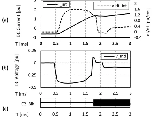
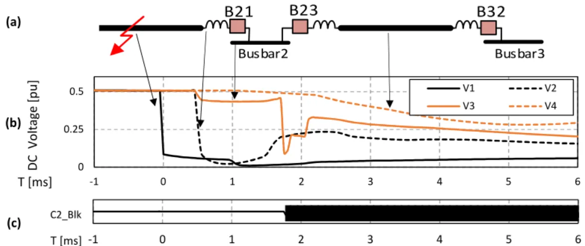
tower dimensions for voltages of (c)±200 kV and (d)±400 kV. . . 47 4.1 Three terminal dc grid with a low impedance fault at link 12. . . 54 4.2 DC current derivative acquired during steady-state operation. . . 57 4.3 Reflection and transmission of waves at fault location. . . 60 4.4 Data associated with relay 21 and converter C2 including (a) current and
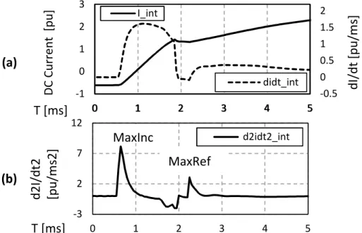
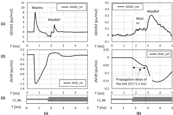
current derivative, (b) voltage across inductor and (c) converter C2 blocking state. . . 61 4.5 (a) voltage at converter C2 terminal and (b) C2 blocking state. . . 63 4.6 (a) DC current with first derivative together with (b) second derivative. The
thresholdsMaxIncandMaxRef are acquired at the second order derivative . 65 4.7 Flowchart with generic magnitudes of currents and voltages at the faulty link,
terminal next to the faulty link, and non-faulty link. . . 66 4.8 Generic profile of current derivative in (a) a faulty link and in (b) a non-faulty
link. . . 67 4.9 Magnitude of dc voltage following a dc fault event. (a) Radial dc network,
(b) dc voltage and (c) blocking of converter at busbar 2. . . 68 4.10 Data analysed by the CRCC algorithm for (a) internal dc relay and (b) an
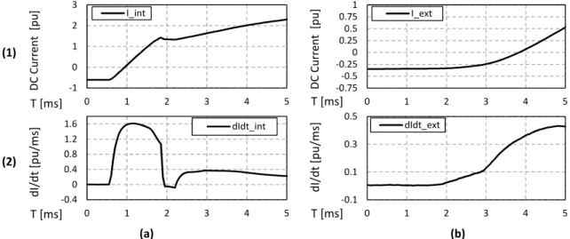
external dc relay. In (a1, b1) dc current second order derivative, (a2, b2) voltage derivative and (a3, b3) converter C2 blocking state. . . 69 4.11 Orientation of the current sensor at the positive and negative pole. . . 70 4.12 DC current measurement at a dc relay (a1) internal and (b1) external to a
faulty link. Similarly, dc current derivative at a dc relay (a2) internal and (b2) external to a faulty link. . . 71 4.13 (a) Non-faulty link and (b) voltage collapse and restoration. . . 72
5.1 Generic dc fault current behaviour. . . 78 5.2 Configuration of a grounding switch. . . 79 5.3 DC voltage behavior following P2Gnd fault and overvoltage suppression
events. . . 82 5.4 Detailed flowchart of the PPS for an individual busbar station. . . 84 5.5 MTDC grid case study with location of the fault scenarios. . . 85
List of figures xxiii
5.6 State of (a) the converters, (b) ACCBs and (c) FDs for the P2P fault case. . 86 5.7 DC (a) link currents, (b) link voltages and (c) converter currents for the P2P
fault case. . . 87 5.8 State of (a) the converters, (b) ACCBs, (c) FDs and (d) grounding switches
for the P2Gnd fault case. . . 90 5.9 (a) DC link currents, (b) dc voltage on positive pole, (c) dc voltage on
negative pole and (d) dc converter current for the P2Gnd fault case. . . 91 5.10 Isolation failure and back-up interlock signal in a busbar station. . . 93 5.11 State of FDs considering failure of dc FD 12 (P2P fault case of Section 5.3.1). 94 5.12 (a) DC link current and (b) FD opening state with the "handshaking" based
strategy without ACCB reclosing. . . 95
6.1 FB submodule with current path during blocking mode. . . 99 6.2 Selection C2 blocking. . . 101 6.3 View of FB submodule representation from the converter model in PSCAD/EMTDC.102 6.4 FB converter configuration with submodule operation during the overvoltage
suppression operation (IGBTs 2 and 4 in closed mode). . . 103 6.5 Application of the overvoltage and voltage imbalance suppression method
during a P2Gnd fault The (a) positive and negative voltage, (b) arm currents and (c) the firing pulses on the IGBTs in a FB submodule. . . 105 6.6 MTDC grid case study with FB converters. The location of the fault scenarios
is shown. . . 109 6.7 Converter blocking P2P . . . 110 6.8 Data analysed by the discrimination algorithms in the internal dc relay 21.
View of (a) dc current, (b) second derivative of dc current together with MaxInc and MaxRef of CRCC criterion and (c) protection signals. . . 111 6.9 Data analysed by the CRCC discrimination criterion in the external dc relay 41.112 6.10 State of FDs following the dc P2P fault. . . 113 6.11 DC currents and voltages at the network. . . 114 6.12 Converter blocking with P2Gnd. . . 114 6.13 Data analysed by the CRCC discrimination criterion in the internal dc relay 24.115 6.14 Data analysed by the CRCC discrimination criterion in the external dc relay 32.117 6.15 DC voltage profiles at converter C2 following the P2Gnd fault where (a)
overvoltage decays naturally and (b) overvoltage is suppressed through FB converter operation. . . 117 6.16 State of FDs following the P2Gnd fault. . . 118
6.17 (a) DC converter current together with dc voltage on the (b) positive pole and on the (c) negative pole. . . 119
7.1 (a) DC fault current profile and (b) DCCB state. . . 125 7.2 Configuration of the discharging circuit with DCCBs. . . 126 7.3 (a) DC fault current on a discharging circuit, (b) dc voltage and (c)
discharg-ing DCCB state. . . 127 7.4 Location of the P2P and P2Gnd faults in the CIGRE 11-terminal dc network. 130 7.5 Converter blocking state . . . 131 7.6 Data analysed by the discrimination algorithms in the internal dc relay 41.
View of (a) dc current, (b) second derivative of dc current together with MaxInc and MaxRef of CRCC criterion, and (c) protection signals. . . 132 7.7 Data analysed by the discrimination algorithms in the external dc relay 89.
View of (a) dc current, (b) second derivative of dc current together with MaxInc and MaxRef of CRCC criterion, and (c) protection signals. . . 133 7.8 Link outage due to opening of link end DCCBs. . . 134 7.9 Profile of (a) converter dc currents and (b) positive pole voltages. . . 135 7.10 DC voltage at monople and bipole dc links due to a positive-P2Gnd fault. . 135 7.11 Converter blocking state. . . 136 7.12 Data analysed by the discrimination algorithms in the internal dc relay 78.
View of (a) dc current, (b) second derivative of dc current together with MaxInc and MaxRef of CRCC criterion, and (c) protection signals. . . 137 7.13 Data analysed by the discrimination algorithms in the external dc relay 98.
View of (a) dc current, (b) second derivative of dc current together with MaxInc and MaxRef of CRCC criterion, and (c) protection signals. . . 138 7.14 Second derivative of dc current at relay 98 (a) with and (b) without a dc-dc
transformer connected at busbar 9. . . 139 7.15 DC link outage due to link end DCCB opening. . . 139 7.16 (a) Current on the discharging circuits, dc voltage at the non-faulty pole and
(c) state of the discharging DCCBs 7 and 8. . . 140 7.17 Profile of (a) converter dc currents, (b) positive pole dc voltages and (c)
negative pole dc voltages. . . 141
A.1 Location of the P2P and P2Gnd fault within the CIGRE 11-terminal dc grid. 158 A.2 Converter blocking state. . . 158
List of figures xxv
A.3 Data analysed by the discrimination algorithms in the internal dc relay 124. View of (a) dc current, (b) second derivative of dc current together with MaxInc and MaxRef of CRCC criterion, and (c) protection signals. . . 159 A.4 Data analysed by the discrimination algorithms in the external dc relay 512.
View of (a) dc current, (b) second derivative of dc current together with MaxInc and MaxRef of CRCC criterion, and (c) protection signals. . . 160 A.5 Link outage due to opening of link end DCCBs. . . 161 A.6 (a) DC voltage recovery and (b) outage of a few dc links. . . 161 A.7 Voltage at the faulty bipole dc link. . . 162 A.8 Converter blocking state. . . 163 A.9 Data analysed by the discrimination algorithms in the internal dc relay 21.
View of (a) dc current, (b) second derivative of dc current together with MaxInc and MaxRef of CRCC criterion, and (c) protection signals. . . 163 A.10 Data analysed by the discrimination algorithms in the external dc relay 32.
View of (a) dc current, (b) second derivative of dc current together with MaxInc and MaxRef of CRCC criterion, and (c) protection signals. . . 164 A.11 DC link outage due to DCCB opening. . . 165 A.12 Profile of (a) converter dc currents, (b) positive pole dc voltages and (c)
List of tables
3.1 Per unit system base values. . . 39 3.2 Converters’ operational modes and settings. . . 41 3.3 Steady-state dc voltages and dc currents at the 4-terminal dc grid [p.u.]. . . 41 3.4 DC link numeration, length and type. . . 42 3.5 Control modes and setpoints of converters. . . 44 3.6 Steady-state dc voltages and dc currents at CIGRE 11-terminal dc grid [p.u.]. 44 3.7 Cable parameters. . . 46 3.8 Link end inductor ratings in the literatures. . . 48 3.9 DC network parameters. . . 51
Chapter 1
Introduction
1.1
Background and Motivation
In April 24, 2017, world population reached 7 500 million people [1]. This number is expected to increase (from 5 278 million in 1990) to 9 700 million people by 2050 [2]. This impressive demographic growth brings numerous social and technological challenges to society including suitability of urban population, food supply, energy demand, among others.
Demographic and industrial growth lead today’s society to be very dependent on electric energy. This can be obtained from various more or less environment friendly sources. Civil society is relatively well educated and aware of their ecological footprint, impacts of fossil resources and of renewable generation. This lead to organisation of numerous initiatives around the world to demand for environment friendly energy policies. As one of the results, an historical mark was achieved by November 4th, 2016, where representatives of 195 countries signed the "Paris Climate Agreement". This is a worldwide deal to mitigate global warming effects in the years to come. The deal includes energy policies to reduce greenhouse gas emissions such as reduction of fossil based energy while increasing the renewable energy generation mix.
Fig. 1.1 illustrates growth of renewable energy capacity worldwide. As observed, the year 2016 transgressed for the first time the 2 000 GW installed capacity. Notwithstanding, a continuous investment in renewable sources of energy is well expected as the way forward.
Fig. 1.1 Global renewable capacity growth by 2016. Courtesy of IRENA [3].
Even renewable energy faces a challenge nowadays: which locations have the most favourable renewable energy potential? Over the last decades, deserts have gathered attention due to the immense solar energy potential. "Within 6 hours, deserts receive more energy from the sun than humankind consumes within a year", quoting [4]. The North Africa desert is particularly of interest as it could fuel Europe with large amounts of renewable energy. The development of such a project is dependent of efficiency of solar cells and transmission network, but mostly of political initiative. A long-term agreement between countries around the Mediterranean Sea would be necessary to provide a sustainable operation strategy, economic compensation, investments costs and maintenance costs.
An area with an immense potential renewable generation of 100 GWh [5] is the North Sea. This offshore energy potential has lead in 2010 to the creation of the North Seas Countries’ Off-shore Grid Initiative, a joint initiate from the energy authorities of the ten countries of the North Sea region. Their mission is to find out the best way to connect the large amounts of available offshore wind energy to mainland Europe. The main goal is to encourage the development of an offshore grid infrastructure with a focus on multi-terminal,
1.1 Background and Motivation 3
multi-vendor, high-voltage direct current (HVDC) transmission system [6]. In addition, European Union has been sponsoring major research projects on the area of offshore grid technologies and HVDC transmission. Examples include the TWENTIES, MEDOW, and PROMOTioN projects [7].
At the present time, a number of point-to-point HVDC links have been built. Fig. 1.2 shows inland and offshore high-voltage links in several countries at the North of Europe. Offshore HVDC links (in purple) are placed in several locations including the North Sea, English Channel, Baltic Sea and Irish Sea.
Fig. 1.2 Map of existing or under-construction high-voltage links around the North Sea and the Baltic Sea regions. Notice that most of the offshore links are in HVDC transmission. Adapted from [8].
There are several economic, technical and social reasons to use dc transmission instead of traditional ac transmission. The break-even distance, occurring when dc transmission becomes economically more attractive than ac transmission, is typically considered to be
∼60-100 km for cables and up to∼800 km for overhead lines (OHLs) [9–11]. In terms of technical advantages, dc links feature fewer power losses and a higher power transmission capacity with the same conductor in comparison with ac transmission. The voltage drop in dc systems is almost negligible and therefore, there is no need of reactive power compensation. Additionally, dc links are ideally free of skin effect and of time varying magnetic field;
thus, dc systems may be used nearby sensitive communication systems. The use of cables is particularly encouraged due to political and environmental constraints on consenting and building new OHLs. Such a consideration led to the construction of the first onshore European HVDC cable, where the construction of new OHLs had social acceptance issues [10].
HVDC transmission systems are classified as back-to-back, point-to-point and multi-terminal dc (MTDC) grids. Back-to-back systems have an inverter and a rectifier stations at the same building (or geographically close). They are used to connect ac grids with different operating frequencies or areas that may be asynchronous. Point-to-point systems are used to transmit large amounts of power from a generation point over long distances to a load point. These constitute currently the most used configuration of HVDC systems. In fact, a number of point-tot-point links has proliferated in several locations around the world. Fig. 1.3 shows the installed capacity of HVDC systems in the world, which has an exponential behaviour.
Fig. 1.3 Evolution of the installed HVDC capacity worldwide [12].
The development of MTDC grids comprise the next technical step. These are formed by connecting more than two converters, resulting in a radial or meshed MTDC grid. This grid is seen as a reliable solution for the next generation of power systems transmission [13, 5, 11]. For instance, it has been recognized that an MTDC grid in the North Sea may bring several benefits, including the exchange of reserves between Great Britain, Norway and Continental European grids, supply of energy to offshore platforms such as gas stations, access to wider power market areas, and an increased security of supply [13]. In spite of
1.2 Research Objectives 5
the great advantages, few MTDC grid projects have been developed so far due to technical challenges, political and economic drivers.
1.2
Research Objectives
The feasibility of dc networks is currently being driven by industrial competition. Areas with substantial research development include HVDC converters, operation and control, power electronic devices, HVDC cables, dc power flow controllers, dc circuit breakers (DCCBs), dc protection strategies, dc-dc transformers and standardisation issues [5, 14–17]. Among these, dc fault protection is recognised as potentially the last major technical barrier to developing reliable MTDC grids.
DC protection can be divided into two categories: dc protection devices and dc protection strategies [5]. Devices that can be used for dc grid protection include DCCBs, converters with current fault blocking (FB) capability and ac circuit breakers (ACCBs) [18, 19], see Fig. 1.4. C B A ACCB Full-bridge converter 3 V+ V (a) (b) (c)
Fig. 1.4 Devices that lead to dc fault clearance include (a) ACCBs, (b) converters with FB capability and (c) DCCBs.
Although high-voltage DCCBs have been thoroughly investigated over the last years, the technology is still commercially unavailable[20]. Even when DCCBs become technically feasible, their integration to HVDC projects may be prohibitive in the short term due to economic constraints. Therefore, alternatives such as ACCBs and converters with fault current blocking capability are under consideration on several dc protection studies.
Ideally, only the faulty link should be isolated from the non-faulty network. However, this approach is only possible if DCCBs are used. In addition,faulty link discrimination comprises a great challenge as well. Discrimination should be based only on local dc currents and voltages and it should be achieved in a period of a few milliseconds only. This is a requirement due to dc fault current rate of change of potentially several kA/ms.
Investigation of protection algorithms for dc grids is being carried out in several direc-tions including adaptability of ac protection methods for dc systems, communication based methods and current or voltage derivative methods. The aim of these algorithms is to quickly detect and discriminate a dc fault. The development of innovative algorithms for dc grid discriminating protection will enhance the feasibility of MTDC grids. This is the main challenge addressed in this thesis where the research objectives are as follows:
1. To develop a fundamental understanding of pole-to-pole (P2P) and pole-to-ground (P2Gnd) fault behaviour, dc protection requirements and modelling of MTDC grids;
2. To propose dc fault discriminating algorithms:
(a) independent of link communication;
(b) robust to link type (cable, OHL, and both cable and OHL in the same link), MTDC grid operation (monopole, bipole) and configuration (radial, meshed).
3. Protection strategies should be developed for grid equipped with:
(a) ACCBs:
all the ACCBs need to open in order to clear dc fault currents. A protection strategy should minimise the negative effects of dc grid outage.
(b) Converters with FB capability:
all the converters are required to block in order to clear dc fault currents. A protection strategy should minimise the negative effects of dc grid outage.
(c) DCCBs:
only the DCCBs placed at the faulty link should open. Hence, a protection strategy should identify the faulty link in a quick and accurate manner.
1.3 Thesis Structure 7
4. Lastly, the strategies with ACCBs, FB converters and DCCBs should include methods to suppress overvoltage events resultant from P2Gnd faults in symmetrical monopole networks.
1.3
Thesis Structure
This thesis is divided in eight chapters, being those organised as follows:
Chapter 1 introduces the topic of research and the work’s motivation. The objectives of the thesis are stated and the publications are given.
Chapter 2 focus on the reviewing the literature on protection for HVDC grids. The challenges and requirements of dc protection are highlighted. Protection algorithms are grouped, described and critically reviewed. Devices that could provide dc fault isolation or clearance are described. Then, a number of protection strategies is given and grouped according to the used fault clearance devices and protection philosophies. The chapter ends with a discussion and prospective research trends in dc protection.
Chapter 3 presents the modelling of MTDC grids, which was performed with PSCAD/EMTDC. Two dc grids are modelled, including a 4-terminal and the CIGRE 11-terminal grid. The pre-fault current and voltage values are given for each grid. Equipment modelling is given in detail, including HVDC converters, dc links, protection devices and logic protection units.
Chapter 4 describes the fault detection and fault discrimination algorithms. The proposed algorithms analyse only local dc current and voltage since communication channels represent a technical restriction for a fast dc protection. In this chapter, two algorithms are given to dis-criminate only the faulty link. A third algorithm is presented to reclose fast dc disconnectors (FDs) of DCCBs, if necessary.
Chapter 5 describes a protection strategy for dc grids equipped with ACCBs. The strategy includes the fault detection and fault discrimination algorithms from Chapter 4. A non-minimum opening philosophy is proposed while a progressive recovery of non-faulty parts of the network is achieved. Overvoltage suppression is performed with discharging circuits. Simulation results are given in detail for a P2P and for a P2Gnd fault case.
Chapter 6 describes a protection strategy for dc grids equipped with converters with FB capability. The strategy includes the fault detection and fault discrimination algorithms from
Chapter 4. A minimum opening philosophy is proposed. An overvoltage suppression method is proposed and takes advantage of the converter configuration. Hence, additional hardware such as link discharging circuits are not necessary. Simulation results are given in detail for a P2P and for a P2Gnd fault case.
Fig. 1.5 illustrates the chapters’ content and connections between chapters.
Literature Review
Conclusions
Overvoltage Suppression with Fast DC Disconnectors
Overvoltage Suppression with Fault Blocking Converters
Overvoltage Suppression with DC Circuit Breakers
Protection Strategy based on ACCBs
Protection Strategy based on FB Converters
Protection Strategy based on DCCBs
MTDC Grid Modelling
4-terminal grid CIGRE 11-terminal grid 2 3 4 5 6 7
8 Appendix AAdditional simulation results
Simulation Results
Simulation Results Simulation Results Fault Detection and Fault Discrimination Algorithms
Introduction 1
Fig. 1.5 Thesis structure per chapter.
Chapter 7 describes a protection strategy for dc grids equipped with DCCBs. The strategy includes the fault detection and fault discrimination algorithms from Chapter 4. A minimum opening philosophy is proposed, hence only the DCCBs discriminated as internal the fault
1.4 List of Publications 9
link are opened. Simulation results are given in detail for a P2P and for a P2Gnd fault case. These faults are applied at the CIGRE 11-terminal dc grid.
The thesis ends with Chapter 8. Conclusions of the thesis are discussed in several categories and a recommendations for future work are suggested.
1.4
List of Publications
During the doctorate study, three document have been written for publication. These resulted from a collaboration between Cardiff University and the industrial sponsor GE’s Grid Solutions (former Alstom Grid UK Ltd). The publications are given below:
1. Rui Dantas, Jun Liang, Carlos E. Ugalde-Loo, Andrzej Adamczyk, Carl Barker, Robert Whitehouse, "Progressive Fault Isolation and Grid Restoration Strategy for MTDC Networks" IEEE Transactions on Power Delivery, (Accepted)
2. Rui Dantas, Jun Liang, Carlos E. Ugalde-Loo, Andrzej Adamczyk, Carl Barker, Robert Whitehouse, "Protection Strategy for Multi-terminal DC Networks with Fault Current Blocking Capability of Converters" in 13th IET International Conference on AC and DC Power Transmission (ACDC 2017), pp. 1–7, Manchester, 2017.
3. Rui Dantas, Jun Liang, Carlos E. Ugalde-Loo, Andrzej Adamczyk, Carl Barker, Robert Whitehouse "DC Grid Protection: Review and Research Trends", Electric Power Systems Research (Under Review)
1.5
List of Contributions
The work developed during this doctorate brings new contribution to the research field of dc grid protection. The main contributions are listed below followed by a brief description.
1. Protection algorithm of comparison of rate of change of dc current (CRCC).
In the literatures, fault discrimination based on travelling waves typically consists on capturing the time period between consecutive waves, which represents a certain distance. The CRCC algorithm differs from existing literature in the way that fault
discrimination is achieved thanks to a magnitude comparison of travelling waves and not due to the time period between travelling waves.
2. Protection strategy for MTDC grids based on ACCBs.
In the literatures, a method that uses ACCBs to clear faults in dc grids is able to isolate the faulty link and restore the network in 500 ms (described at Section 2.5.1). In this thesis, a progressive strategy is proposed which is able to reduce the grid outage time and offers back-up protection. These methods are compared in section 5.4.2.
3. Protection strategy for MTDC grids based on FB converters.
In literature, not much attention is paid to converters with fault blocking capability (reviewed at Section 2.5.2). In this thesis, a protection strategy is developed to clear and isolate a dc fault, thanks to the operation of FB converters and dc link disconnectors.
4. Protection strategy for MTDC grids based on DCCBs.
There are several algorithms in the literature that consider DCCBs for dc fault protec-tion and a few protecprotec-tion philosophies might be possible (as detailed at Secprotec-tions 2.5.3 and 2.5.4). In this thesis, DCCBs are operated according to the proposed discrimina-tion algorithms (as the CRCC) while the MTDC grid model is of high complexity (11 terminal CIGRE dc network as seen at Section 7.3).
5. Overvoltage suppression methods with FB converters.
In literatures, overvoltage suppression is typically based on switches that connect a link pole to the ground. In this thesis, these devices are not required for grids equipped with FB converters as these are able to provide the overvoltage suppression function.
6. Publication of an IEEE paper and presentation in an IET conference.
Dissemination of the findings has been made through a publication in a international recognised journal and presentation in a internationally recognised conference. At the time of writing, these is a still other journal publication waiting for decision. In addition, all the research finding were shared with the industrial sponsor.
1.6 Project Participation 11
1.6
Project Participation
The doctorate thesis was funded by the project "DC Grid Discriminating Protection", de-livered by GE’s Grid Solutions (former Alstom Grid UK Ltd) to School of Engineering, Cardiff University, UK. The project had a three years duration and ran from 01/04/2014 until 31/03/2017.
The working tasks include investigation of fault detection and discrimination strategies for a simple 4-terminal dc grid and for the CIGRE 11-terminal dc grid.
Chapter 2
Literature Review
2.1
Introduction
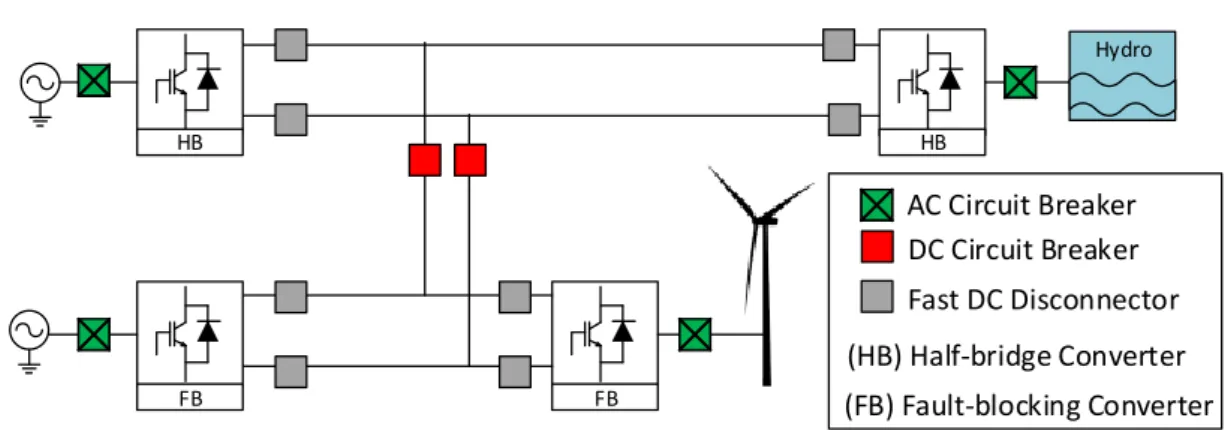
In recent years, projects with large power generation capabilities harvesting energy from renewable sources have appeared. Examples include the 6.4 GW Xiangjiaba hydro power plant in China [21] and offshore wind farms in the North Sea [13]. Other technically challenging ideas that have been considered include a mainland European Supergrid [22] transmitting large amounts of wind and hydro power from the North and solar power from the South to a number of European countries [9]. These projects share a common geographical constraint: power generation is available in remote locations which are far from cities and main load centres. Although the construction of such environmentally friendly energy projects requires political cooperation between countries, the technical issues may be overcome by adopting HVDC power transmission [14].
Substantial research has been carried out into dc grids, particularly for open sea areas, in terms of topologies and control [23]. However, offshore wind farm configurations are greatly dependent on the cost of laying cables and of the adopted protection devices, which in turn have a direct influence on the selection of a dc protection strategy in terms of the maximum power loss allowed following a fault.
Protection is currently one of the main technical impediments for the construction of a MTDC grid. ACCBs can adequately protect point-to-point HVDC connections, but the same protection concept might not be easily acceptable for an MTDC grid as the de-energization of the entire system is required [24]. Converters with FB capability are able to interrupt
the ac infeed current to the dc side, and hence, clear dc faults currents [25]. This option is faster than using traditional ACCBs but comes at a cost. DC circuit breakers (DCCBs) are a potential solution to selectively isolate a faulty link [26, 27]. However, two major aspects have to be considered regarding the hardware and software of future protection units. Firstly, DCCBs may have limited current breaking capabilities [11]. Secondly, dc protection algorithms are not established yet and represent a technology still underdeveloped [5]. It is agreed though that methods leading to a logical decision of opening (or not) a DCCB based on local measurements should ensure discrimination in a fast and reliable manner.
This Chapter carries out an in-depth critique review of dc fault discrimination methods and covers the protection methodologies and devices available in the open literature. In addition, improvements to existing dc protection strategies are suggested and trends for the next generation of protection strategies are discussed.
2.2
Challenges of DC Protection
DC fault clearing is very challenging as both the breaking operation and time requirements are more demanding than those for ac fault clearing. Firstly, in dc systems there is no natural zero-crossing point, meaning that dc currents have to be driven to zero and the fault energy has to be dissipated by the interrupting device. Secondly, dc fault currents should be interrupted within a few milliseconds to limit the prospective fault current magnitude. In [16] a period of less than 2 ms is recommended for fault clearance, which is a much shorter time in comparison to ac protection. This is due to the low link impedance and the fast current increasing behaviour, which can be of tens of kA/ms [28]. The recommended time period is a challenging target that may become feasible if fast dc current clearance devices such as fast DCCBs or FB converters are employed.
Fault current breaking devices and discriminative protection strategies are a major re-search topic in HVDC. In this context, the DCCB has been identified as a key component, although it is not yet commercially available. However, the use of other fault interruption devices such as FB converters may justify the avoidance of DCCBs in dc grids. In addition, the use of traditional ACCBs might be feasible for a dc network of limited size. Hence, dc protection comprises a wide area of research with a number of potential research directions.
2.2 Challenges of DC Protection 15
2.2.1
Requirements for Protection
The main protection requirements for ac or dc networks are listed below [14, 16]:
(a) Sensitivity: detection of a faulty link only if a fault is present (not in normal operation);
(b) Discrimination (or selectivity): correct identification of faulty and non-faulty links;
(c) Speed: the maximum combined fault detection time and protection operation time must be short enough to prevent equipment damage and system instability;
(d) Reliability: the protection scheme performs correctly by considering main and backup criteria;
(e) Seamlessness: after the fault clearance, the remaining part of the system continues to operate in a secure state;
(f) Robustness: detection of faults in normal or degraded mode and discrimination from any operational events.
2.2.2
Grid Behavior Under a DC Fault
A number of factors contribute to the severity of a dc fault. The current and voltage behaviour is influenced by fault resistance, equivalent capacitance of links and converters, fault location, short circuit ratio of the ac network and current rate limiting devices, if applicable [26]. If current rate limiting dc reactors are used at the dc link ends, an extra time of a few milliseconds is allowed for protection decision-making and operation. The current rising rate limit is given by
di dt =
∆Vmax
L (2.1)
where∆Vmaxis the maximum P2Gnd voltage. The design of dc reactorLshould comply with
the maximum breaking capabilities and decision time of the protection scheme. For example, for a 320 kV dc grid with 10% maximum overvoltage, a reactor of 100 mH is recommended to limit the current rise to 3.5 kA/ms [27].
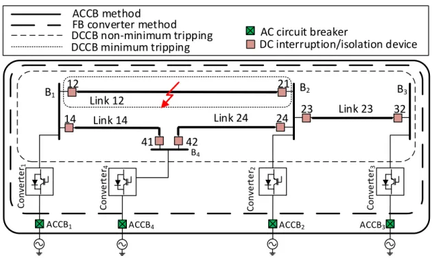
In order to illustrate the voltage and current profile during a dc fault, a 4-terminal dc grid has been modelled (see Fig. 2.1). The dc network operates with a dc voltage of±200
kV and has half-bridge (HB) modular multi-level converters (MMCs). These converters are chosen as are a research preference of the industrial sponsor.
The dc cables are represented as frequency dependent (phase) models. Links 12, 14 and 24 have a length of 200 km while link 23 has a length of 50 km. A 50 mH current rate limiting device is considered at each link end. A grounding point is placed between each ACCB and converter station. This is composed of a star inductance with a high impedance earthing arrangement [29]. B1 B2 B3 B4 C o n ve rt e r4 ACCB4 C o n ve rt e r1 ACCB1 C o n ve rt e r2 ACCB2 C o n ve rt e r3 ACCB3 21 23 32 14 12 Link 12 Link 24 Link 14 Link 23 41 42 24
Fig. 2.1 Four-terminal dc network.
A fault is modelled as a time controlled switch in series with a resistance. These are placed between the positive pole and the negative pole; and between the positive pole and ground. The development of a fault with an arcing period and its potential effects, such as modification of travelling wave fronts, are not analysed in this thesis and are recommended for future research.
P2Gnd and P2P faults are described in this Section. Fig. 2.2 illustrates generic profiles for dc current and dc voltage. These are based on a positive-P2Gnd and a P2P fault occurring at 2 ms in the middle of link 12 (see Fig. 2.1) while current and voltage profiles are captured on dc relay 12.
P2Gnd faults in symmetrical monopole topologies lead to a voltage shift: the voltage of the faulty pole moves towards the ground level, pushing the voltage on the other pole to twice the pre-fault value as seen in Fig. 2.2 (a). This event causes an overvoltage. During this transition, a temporary current oscillation occurs which might not be sensed by overcurrent algorithms (Fig. 2.2 (c)). In practical HVDC schemes, pole insulation is typically protected against overvoltage by surge arresters with a protective level below 1.85 p.u.
2.3 Fault Detection and Discrimination Methods 17
P2P faults imply more severe conditions to dc links and the surrounding equipment. An overcurrent might occur in the links of the whole grid, with a rate of rise that could reach tens of kA/ms (Fig. 2.2 (d)) [30]. This occurs with a quick (but not instantaneous) voltage collapse in all dc terminals as seen in Fig. 2.2 (b).
-1.25 -1 -0.75 -0.5 -0.25 0 0.25 0.5 0.75 0 10 20 30 40 50 Vp Vn T [ms] D C Vo ltage [p u ] (a) -0.6 -0.4 -0.2 0 0.2 0.4 0.6 0 10 20 30 40 50 Vp Vn T [ms] D C Vo ltage [p u ] (b) -1 -0.5 0 0.5 1 1.5 2 2.5 0 10 20 30 40 50 Ip In T [ms] D C Cu rren t [p u ] (c) -15 -10 -5 0 5 10 15 0 10 20 30 40 50 Ip In T [ms] D C Cu rrent [p u ] (d)
Fig. 2.2 DC voltage profile for (a) a positive-P2Gnd fault in symetric monopole grid and (b) for a P2P fault. DC current profiles for (c) a positive-P2Gnd fault and (d) a P2P fault.
2.3
Fault Detection and Discrimination Methods
The role of a protection strategy for dc links is given Fig. 2.3. Current and voltage sensors are placed at each dc line end. These data are processed by a number of algorithms in a logic unit. Protection algorithms are categorised in three groups. Firstly, fault detection algorithms identify disturbance on a network. Secondly, fault discrimination algorithms identify the faulty link within a network. Lastly, fault location algorithms identify the approximate location of the fault within a known faulty link (i.e.fault distance to a link end).
In this Section, attention is paid to fault detection and fault discrimination algorithms while fault location is not treated. It could be argued that fault detection is not problematic
Detection Discrimination Location Sensors
(dc current and voltage)
Decisions (protection algorithms)
Actions (e.g. opening breakers)
Fig. 2.3 Role of protection systems and stages of a protection strategy.
in MTDC grids since it may be achieved within 1 ms after the arrival of transient waves by using methods based on overcurrent, undervoltage, current derivative or voltage derivative [31]. Fault discrimination has been identified as the most challenging task from dc network protection [20]. Therefore, link discrimination due to dc faults ’is the main scope. Protection of busbars, converter stations, filters and other equipment is out of the scope of this Section.
2.3.1
Current and Voltage Magnitude-Based Methods
Overcurrent and directional overcurrent protection are simple methods to detect a fault either on ac or dc grids. A combination of magnitude, direction and duration criteria may be used to achieve partial discrimination.
The magnitude criterion is determined by either a fixed or a variable threshold correspond-ing to currents larger than the nominal link ratcorrespond-ing. The local direction criterion is determined by the current flow change at the initial transient stage of a fault. If current flows from the dc link to a busbar, the fault must be external. However, if the current flows from a busbar to the dc link, the fault can be either internal or external. Hence, only partial discrimination is achieved when the local direction current criterion is employed.
Fig. 2.4 illustrates the dc current profile for a potential internal dc fault (relay 12) and for an external dc fault (relay 23). On the potential internal fault, the dc current experiences an increasing behaviour after the arrival of the transient waves. This occurs at both ends of the faulty link and typically in one end of the non-faulty links. Moreover, if the dc current experiences a decreasing behaviour, this indicates that the fault is flowing from the dc link to the busbar. As a consequence, the fault must be external. The previous scenarios are valid
2.3 Fault Detection and Discrimination Methods 19
for a current sensor orientation from the busbar to the dc link. Hence, partial discrimination is easily achieved with the local current direction criterion.
-1 0 1 2 3 4 5 6 7 0 2 4 6 8 10 IdcInt D C Curr en t [p u ] T [ms] (a) -4 -3 -2 -1 0 1 0 2 4 6 8 10 T [ms] D C C u rr en t [p u ] (b)
Fig. 2.4 DC current for (a) a potential internal fault and for (b) an external fault.
Voltage-based methods include undervoltage and overvoltage approaches [31]. The positive and negative pole voltages are monitored continuously, making protection decisions in accordance with predefined thresholds. These include a minimum and maximum voltage to detect cases of undervoltage or overvoltage. Fault detection by undervoltage is relatively faster than fault detection by overcurrent due to the transient capacitive discharge of dc links.
Similarly to local current methods, fault detection is easily achieved. However, discrimi-nation may not be accomplished due to the fast voltage collapse in all dc terminals.
2.3.2
Derivative-Based Methods
Current and voltage derivative methods are suitable not only for dc fault detection but also for dc fault discrimination. A dc fault can be detected and/or discriminated by comparing the magnitude of a derivative signal with predefined thresholds [32].
In the case of a dc fault, the dc current and dc voltage change faster in the faulty link than in the non-faulty ones. To make this method practically feasible in dc networks, dc fault current rate limiting devices should be employed at the dc link ends. These devices, also know as link end inductors, perform as a smoothing barrier between the faulty and healthy parts of an MTDC grid [33]. The dc inductors have a negligible influence on the steady-state operation. However, in the case of a disturbance, the dc current rate of rising is limited and the voltage across the device is proportional toL×di/dt. Hence, the thresholds considered by derivative-based methods are highly dependent on the rating of the link end inductors.
Without these, it would be difficult to distinguish an internal fault at the far end of the link from an external fault electrically close to the far end busbar. It should be borne in mind that the design of large dc reactors represents a technical challenge, an increased investment and an increased operational cost.
In [34], a discrimination algorithm employing three criteria is proposed. It includes a dc current rate of change criterion within a predefined time window (thus overcoming the noise disadvantage), a dc voltage derivative criterion and a current leakage criterion. In [32], a fault discrimination algorithm is proposed based on voltage derivative levels in combination with undervoltage and current direction criteria. In [35, 36, 33], the differential voltage magnitude, measured across the current rate limiting device at the transient stage, is used to discriminate a fault as internal or external. The strategy used in [37] considers a voltage derivative function to discriminate the faulty link within an MTDC grid. The strategies in [35, 36, 33, 37] take into account the damping provided by the current rate limiting device. Fault discrimination can be supported by other criteria; e.g. current direction of the first transient wave.
The discrimination approaches discussed in the previous references are slightly different among them but have the derivative method as the main core. With well-designed thresholds, this method leads to a correct discrimination of the faulty dc link at an early stage after the start of the fault. However, such a derivative approach has a few drawbacks. These include the sensitivity to noise interference, to fault impedance and to the rating of the current rate limiting device, which must be minimised. In addition, this method has been tested in networks mainly composed of cable links. The presence of overhead lines (OHLs) within the network might require adaptation of pre-set thresholds or of the rating of the current rate limiting device. Hence, this leaves a margin for further validation of the derivative concept on wider grid configurations.
Fig. 2.5 illustrates the current and voltage derivative profiles for a P2P fault at the middle of link 12 as seen by relay 12 (see Fig. 2.1). In Fig. 2.5 (a, c), the dc fault is applied on a cable while in Fig. 2.5 (b, d), dc fault is applied on a OHL (link 12 is replaced by an OHL). The magnitude of the derivative signal is the value compared with pre-set thresholds and that leads to fault discrimination. These values are slightly different between the two cases, which means that the thresholds should be different too. In addition, OHLs have a noticeable
2.3 Fault Detection and Discrimination Methods 21 -0.2 0 0.2 0.4 0.6 0.8 1 0 2 4 6 8 10 d I/ d t [p u /ms] T [ms] (a) -1 -0.5 0 0.5 1 1.5 0 2 4 6 8 10 d I/ d t [p u /ms] T [ms] (b) -0.25 -0.2 -0.15 -0.1 -0.05 0 0.05 0.1 0 2 4 6 8 10 d V /d t [p u /m s] T [ms] (c) -0.4 -0.3 -0.2 -0.1 0 0.1 0.2 0.3 0 2 4 6 8 10 d V /d t [p u /ms ] T [ms] (d)
Fig. 2.5 DC current derivative profile (a) in a cable and (b) in an OHL. DC voltage derivative profiles in (c) a faulty cable and (d) in a faulty OHL.
high-frequency component which may affect the accuracy of sensors, causing calculation errors and a potential incorrect discrimination judgement. The discrimination algorithms proposed in this thesis (Section 4.3) minimise the issues aforementioned. The algorithm in Section 4.3.1 uses current derivative functions but does not require pre-set thresholds, which would be hard to calculate due to different link types and grid configurations.
2.3.3
Unit Protection Methods
The knowledge of the input and the output data of a dc link leads to a single equipment protection approach, know as unit protection. A communication channel is therefore required between both link ends. Hence, the link end relays have the ability to exchange information between them, but at the expense of a delay. Correspondingly, if only local data is available, a protection strategy falls in the non-unit protection approach.
Methodologies to achieve fault discrimination within the unit protection approach include the current difference and the current direction schemes (even with high impedance faults)
[38, 29]. The first method is based on the current differenceIdiffbetween two sensors placed
at the ends of the same dc link. In steady state, Idiff is equal to zero (neglecting noise interference and power losses); however, in the case of an internal fault,Idiff increases as the infeed current from both ends is different in magnitude. OnceIdiff transgresses a pre-set
threshold, the fault is discriminated as internal to the link. The second method is based on the comparison of the directions of dc current at the same pole and link. Hence, if both directions are positive, the fault must be internal. Conversely, if one current direction is negative, the fault must be external to that link.
Communication between dc relays is possible by adding a channel in parallel with the power dc link connecting both link ends; however, this induces transmission and processing time delays. Dedicated or non-dedicated communication channels for HVDC applications may be based on optical fibre technology. If the channel is dedicated exclusively to protection proposes, a transmission delay of 1 ms per 200 km may be incurred [38]. Although such a small transmission delay value is theoretically possible, in practice a larger delay is expected. Non-dedicated channels exhibit larger delays as the exchanged data packages are used not only for protection but also for other purposes such as control. For these channels, an additional delay may be considered in the case of corrupted data, which may be corrected by re-sending data packages. The processing delay (data concentrating, multiplexing and delay associated with transducers) is an ambiguous quantity and its measurement is not specified in current standards [39].
Time synchronisation is generally required in relays at both link ends for a suitable application of discriminative methods. This implies adding a delay that matches the link propagation constant delay (defined as γ(ω) =
√
ZY, where Z = R+ jωL is the series
impedance andY =G+jωCis the shunt admittance of the link).
Fig. 2.6 illustrates the application of the current difference method for a dc relay internal and a dc relay external to the faulty link. A positive-P2Gnd fault is considered in the middle of link 12. Relay 12 is internal and relay 23 external to the faulty link. Signal’Iloc’represents the local current,’Irem’ the remote current and ’Idiff’ the difference between both’Iloc’and
’Irem’. A communication delay of 10 ms is assumed. It can be observed that for the internal relay (Fig. 2.6 (a)),’Idiff ’initially increases. This occurs due to the initial positive rate of change of current on both ends of the faulty link. As a result, the fault is classified as internal.
2.3 Fault Detection and Discrimination Methods 23
Correspondingly, for the external relay (Fig. 2.6 (b)),’Idiff ’initially decreases. As a result, the fault is classified as external.
-2 -1 0 1 2 3 4 5 0 5 10 15 20 25 30 Iloc Irem Idiff D C C u rre n t [p u ] T [ms] (a) -0.6 -0.4 -0.2 0 0.2 0.4 0 5 10 15 20 25 30
Iloc Irem Idiff
D C C u rre n t [p u ] T [ms] (b)
Fig. 2.6 DC current difference for (a) internal and (b) external fault.
It should be emphasised that the previously discussed time constraints may not be suitable for fast dc protection actions –especially considering long dc links. The China Southern Power Grid has HVDC links of nearly 1000 km [40]; these conditions introduce considerable time delays. Therefore, communication-based methods may be used only as backup protection for MTDC grids. Conversely, for short link lengths, these methods may be adapted to the main protection algorithms –as in the case of a number of submarine grids [41]. It should be known that the protection algorithms proposed in this thesis do not require dc link communications. Therefore, associated costs with link communication channels are avoided while fault discrimination is equally ensured.
2.3.4
Signal Processing and Other Methods
Signal processing techniques have been used in HVDC point-to-point configurations to detect the fault location within a known faulty dc link [42]. Adaptation of such techniques for fault location between links in radial or meshed dc grids is currently an expanding research area. Travelling wave methods are based on the waves resulting from disturbances. These waves propagate along the dc link causing high-frequency oscillations which are continuously attenuated until they disappear. The wavelet analysis can be then used to decompose the characteristics of travelling waves [43]. Wavelets are defined by the wavelet function and a scaling function in the time domain [44].
The application of travelling wave-based methods relies on the accurate detection of arrival times between wave-fronts or on the energy of the travelling waves. These methods require an adequate equipment modelling and sensors with high sampling rate data from a few milliseconds interval –depending on the link propagation delay and link length [45, 46]. Additionally, a few milliseconds should be accounted for processing time [45]. Reference [47] provides practical techniques for detecting transient wave-fronts.
A different discrimination approach includes the distance (or impedance) protection method. This is commonly used in high-voltage ac networks as it achieves a highly successful rate of fault discrimination. It is based on the continuous monitoring of current and voltage, from where impedance Z is calculated and represented over an R-X plane. A number of boundaries or zones of protection are defined in this plane, including at least a primary and one backup protection zone [48]. Fault discrimination is achieved if the impedance seen by the relays falls within a zone during a pre-determined period of time.
The adaptation of the distance method to dc grids has been considered mainly for fault location [49]. Fault discrimination with the distance protection approach is challenging due to the initial transient current and voltage waveforms upon a fault, as these have high change rates which may induce measurement errors. Moreover, the grid frequency changes abruptly during the transient stage and no fundamental frequency can be defined for distance protection calculations.
2.3.5
Comparison and Discussion
Fault detection on dc grids can be based on simple methods such as undervoltage or derivative functions. However, fault discrimination is the main challenge. The local current direction criterion gives partial discrimination and should be considered as part of a primary protection strategy due to its simplicity. Current direction based on unit protection can also achieve discrimination. However, the use of communication-based methods is highly unlikely to be adopted as primary protection scheme, at least in the case of low impedance faults. This is due to the delay introduced by the communication channel and the processing delay which is highly dependent on the technology adopted.
The best-recognized fault discrimination algorithms are based on the current or voltage derivative approach. These are quick since the incident transient wave contains most of the
2.4 Converters, Fault Clearance and Isolation Devices 25
information required for decision making. These methods rely on the rating of current rate limiting devices which work as a separation between a faulty area and a non-faulty area. The feasibility of this method for dc OHLs and for P2Gnd faults on symmetrical monopole configurations requires more development as less attention is typically paid to these type of links and fault. Hence, the derivative method, although very promising, still has a room for improvement and validation.
Travelling wave-based methods with one terminal data analysis may have good discrim-ination characteristics but are highly dependent on the grid configuration. For example, these methods should be sensitive to the multiple reflections on meshed dc grids, to the grid configuration change (for example, due to the outage of dc links for maintenance purposes) and to the presence of OHLs and cables.
2.4
Converters, Fault Clearance and Isolation Devices
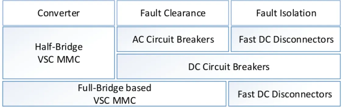
Protection strategies for MTDC grids are being developed using different converter types and current breaking technologies. This section gives a description of these devices together with combinations of them for protection purposes. Devices that lead to dc fault clearance include ACCBs, DCCBs and converters with FB capability.Devices that lead to dc fault isolation include DCCBs and fast (or ultra-fast) dc disconnectors. Fig. 2.7 shows a number of combinations of devices to protect a network against dc faults.
Half-Bridge VSC MMC
Full-Bridge based VSC MMC
Converter Fault Clearance Fault Isolation
AC Circuit Breakers
DC Circuit Breakers
Fast DC Disconnectors
Fast DC Disconnectors
Fig. 2.7 Three combinations of potential protective devices for HVDC grids equipped with MMCs.
2.4.1
Converters for HVDC grids
Several types of converters appeared to serve HVDC transmission. Along the times, convert-ers have evolved accordingly to power electronics technology. The main devices historically used on converters include the hot cathode (1920s-1960s), mercury-arc valve (since the 1930s), thyristor (since 1972), gate turn-off thyristor (GTO) and insulated-gate bipolar tran-sistors (IGBTs), (since 1997) [50]. In terms of converter topology, these are mainly based on:
(a) Line commutated converter (LCC) built with mercury-arc valves (until the 1970s) or with thyristors (until present day) [20];
(b) Voltage source converter (VSC) built with switches with turn-off capability, as GTOs and IGBTs(since 1997) [51, 52]
VSCs appeared following developments in GTOs and IGBTs. These converters have several advantages over LLCs [20, 53]. VSCs do not require reactive power support and power control can be achieved on the fourP-Qquadrants. Power reversal is easily obtained by changing the current direction while keeping the voltage level; thus it allows an easier integration with MTDC grids [14]. For this reason, industrial and academic research studies focus nowadays largely on VSC based converters.
VSCs also evolved along times. The topologies built to manufacture VSCs started with the two-level converter (1997 [54]), moving to the three-level converter (2002 [55]) and later to the promising technology with a MMC (2010, [56]).
MMCs were proposed in 2003 [57] and their first commercial application took place in 2010 [56]. Internally, an MMC is formed by an upper and a lower arm per phase. Each arm contains a smoothing inductance and a number of submodules, each one representing a voltage step. DC voltage rating is achieved in a scalable manner by arranging submodules in series.
Advantage os VSC based MMC technology includes the ability to operate in weak ac grids, black-start capability, fine control or active and reactive components and insignificant level of harmonic generation (hence filters may be not required).
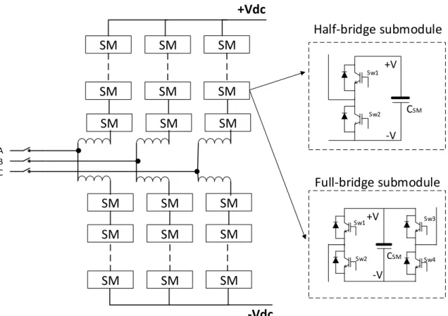
Fig. 2.8 shows the configuration of an MMC. The submodules can be based on HB or full-bridge configurations.
2.4 Converters, Fault Clearance and Isolation Devices 27
SM
SM
SM
SM
SM
SM
+Vdc
-Vdc
SM
SM
SM
SM
SM
SM
SM
SM
SM
SM
SM
SM
A B C CSM Sw2 Sw1 +V -V CSM Sw2 Sw1 Sw3 Sw4 +V -VHalf-bridge submodule
Full-bridge submodule
Fig. 2.8 MMC converter topology with submodule based on HB or FB configuration.
Half-Bridge Based Converters
Converters based on HB submodules are widely used in the HVDC market. HB based converters do not have fault clearance capability. During the transient fault, an ac infeed current flows through the uncontrolled free-wheeling diodes from the ac side to the dc fault side.
In order to protect the converter’s diodes, a protective bypass switch and/or a thyristor is fired following fault detection. This allows most of the current to flow through the bypass device and not through the diodes [58, 59]. Fig. 2.9 illustrates a more detailed view of an HB submodule that includes a protective thyristor and bypass switch.
Full-Bridge Based Converters
In comparison with HB submodule converters (which have positive and zero voltage as output states), MMCs equipped with FB submodules can have three output states: positive voltage, zero voltage and negative voltage. This functionality gives the converter the possibility to
C
SM Sw2Sw1
+V
-V
VSMFig. 2.9 Detailed view of an HB submodule of an MMC converter.
control and/or suppress dc currents. During dc faults, the current interruption can be achieved by removing the gate signals of all IGBTs, where the fault current path is illustrated in Fig. 2.10. The submodule voltage opposes the dc voltage and current flow decays to zero within a few milliseconds. In addition, an FB converter can operate as a static synchronous compensator (STATCOM), even during a dc fault, and support the ac side voltage [19].
C
SMSw2
Sw1
Sw3
Sw4
+V
-V
I
L
arm
Fig. 2.10 FB MMC with submodule and fault current conduction path while in blocking mode.
FB converters are not limited to the full-bridge technology in each arm submodule, as other configurations might be included within this category. Examples include the alternate arm converter, which has an alternative topology based on FB submodules and director switches in each arm [19]. It aims to reduce investment and operation costs while keeping the benefits of a current interruption capability. In [60] a fault tolerant converter is described with FB cells on the ac side. These designs are also able to interrupt the ac side contribution to a dc side fault.
![Fig. 2.11 An hybrid DCCB and operational steps for dc current interruption [62].](https://thumb-us.123doks.com/thumbv2/123dok_us/10179805.2920376/58.892.193.692.162.440/fig-hybrid-dccb-operational-steps-dc-current-interruption.webp)