Master’s Degree Programme in Security and Mobile Computing
Rajat Kandoi
Deploying Software-Defined Networks:
a Telco Perspective
Master’s Thesis Espoo, July 15, 2015
Supervisors: Professor Tuomas Aura, Aalto University, Finland
Professor Markus Hidell, KTH Royal Institute of Technology, Sweden Advisors: Markku Antikainen M.Sc. (Tech.), Aalto University, Finland
Master’s Degree Programme in Security and Mobile Computing ABSTRACT OF MASTER’S THESIS Author: Rajat Kandoi
Title: Deploying Software-Defined Networks: a Telco Perspective
Date: July 15, 2015 Pages: 77
Professorship: Data Communication Software Code: T-110 Supervisors: Professor Tuomas Aura
Professor Markus Hidell
Advisors: Markku Antikainen M.Sc. (Tech.) Sumanta Saha M.Sc. (Tech.)
Software-Defined Networking (SDN) proposes a new network architecture in which the control plane and forwarding plane are decoupled. SDN can improve network efficiency and ease of management through the centralization of the con-trol and policy decisions. However, SDN deployments are currently limited to data-center and experimental environments. This thesis surveys the deployment of SDN from the perspective of a telecommunication network operator. We dis-cuss the strategies which enable the operator to migrate to a network in which both SDN and legacy devices interoperate. As a synthesis of existing technologies and protocols, we formulate an automated process for the bootstrapping of newly deployed forwarding devices. Furthermore, we review solutions for programming the forwarding devices and for performing topology discovery. The functional correctness of the proposed bootstrapping process is evaluated in an emulated environment.
Keywords: SDN, bootstrap, southbound protocols, topology discovery Language: English
First and foremost, I would like to thank my supervisors and advisors for their guidance and support. The weekly discussions with Tuomas Aura and Markku Antikainen were highly constructive and guided my research direc-tion. Markus Hidell provided deep insights into the structure and content of the report. Sumanta Saha’s guidance has allowed me to apply the knowledge I have acquired through the thesis immediately into my work at the industry. I would also like to thank my manager, Antti Miettinen. He constantly followed up on my progress and was obliging in allowing me to work remotely from the university on several occasions.
Lastly, I would like to thank my family for their support; my wife who kept me motivated to complete the thesis work in time, and my parents, without whom none of this would have been possible.
Espoo, July 15, 2015 Rajat Kandoi
ACL Access Control List
API Application Programming Interface ARP Address Resolution Protocol
AS Autonomous System
BGP Border Gateway Protocol
BGP-LS Border Gateway Protocol Link State BOOTP Bootstrap Protocol
BDDP Broadcast Domain Discovery Protocol
CA Certificate Authority
CLI Command Line Interface
CMP Certificate Management Protocol CRL Certificate Revocation List
DHCP Dynamic Host Configuration Protocol
DN Distinguished Name
DSL Digital Subscriber Line
DSLAM Digital Subscriber Line Access Multiplexer FIB Forwarding Information Base
GMPLS Generalized Multiprotocol Label Switching HTTP Hypertext Transfer Protocol
I2RS Interface To Routing System IETF Internet Engineering Task Force IAK Initial Authentication Key
ICT Information and Communications Technology IGP Interior Gateway Protocol
IP Internet Protocol
IS-IS Intermediate System - Intermediate System
IPSec IP Security
L2 Layer 2 (of the network protocol stack) L3 Layer 3 (of the network protocol stack)
LAN Local Area Network
LSPDB Label Switched Path Database
LTE Long-Term Evolution
MAC Media Access Control
MIB Management Information Database MPLS Multiprotocol Label Switching NFV Network Functions Virtualization
NLRI Network Layer Reachability Information
NMS Network Management System
NOC Network Operations Ceneter
OID Object Identifier
OSPF Open Shortest Path First OTN Optical Transport Network
OS Operating System
PCC Path Computation Client
PCE Path Computation Element
PCEP Path Computation Element Communication Protocol
PE Provider Edge
PKI Public Key Infrastructure PKIX Public Key Infrastructure X.509 PON Passive Optical Network
PSK Pre-shared key
RA Registration Authority
SCEP Simple Certificate Enrollment Protocol SDN Software-Defined Networking
SNMP Simple Network Management Protocol
SSH Secure Shell
SSL Secure Sockets Layer
STP Spanning Tree Protocol
TCP Transmission Control Protocol TED Traffic Engineering Database TFTP Trivial File Transfer Protocol TLS Transport Layer Security
TLV Type-Length-Value
URL Uniform Resource Locator
USB Universal Serial Bus
VLAN Virtual Local Area Network XML Extensible Markup Language
Abbreviations and Acronyms 6 1 Introduction 11 1.1 Problem statement . . . 11 1.2 Motivation . . . 12 1.3 Contribution . . . 12 1.4 Research methodology . . . 13
1.5 Sustainable development aspects . . . 13
1.6 Structure of the thesis . . . 14
2 Background on network technologies 15 2.1 Introduction to SDN . . . 15
2.2 Network sections . . . 18
2.3 Public key infrastructure . . . 18
2.3.1 PKI model . . . 20
2.3.2 Certificate management protocols . . . 21
2.3.3 Motivation for using digital certificates . . . 22
2.4 Southbound protocols . . . 22
2.4.1 OpenFlow . . . 23
2.4.2 Path computation element communication protocol (PCEP) . . . 25
2.4.3 Interface to routing system (I2RS) . . . 25
2.4.4 BGP flow-spec . . . 27
2.4.5 Simple network management protocol (SNMP) . . . 27
2.4.6 NETCONF . . . 28
2.5 Protocols for topology discovery . . . 29
2.5.1 Simple network management protocol (SNMP) . . . 30
2.5.2 Link layer discovery protocol (LLDP) . . . 30
2.5.3 BGP link-state (BGP-LS) . . . 31
3.2 Bringing up a device . . . 35
3.2.1 Enabling IP connectivity . . . 35
3.2.2 Enabling Remote Management . . . 37
3.3 Bootstrapping security . . . 37
3.3.1 Installing the operator root certificate . . . 37
3.3.2 Provisioning a domain certificate . . . 38
3.3.3 Bringing up a remote device outside the secure opera-tor network . . . 40
3.3.4 Enhanced security with logging servers . . . 40
3.4 Topology discovery . . . 42
3.4.1 Topology discovery in pure SDN networks . . . 42
3.4.2 Topology discovery in pure legacy networks . . . 44
3.4.3 Topology discovery in hybrid SDN networks . . . 44
3.4.4 Limitations of discussed protocols . . . 46
3.5 Packet forwarding . . . 46
3.5.1 Forwarding in aggregation and core networks . . . 46
3.5.2 Unified control of transport and IP networks . . . 47
3.5.3 Centralized inter-domain routing . . . 48
3.6 Summary . . . 50
4 Implementation and evaluation 51 4.1 Emulation testbed . . . 51
4.1.1 Emulation topology . . . 52
4.1.2 Tools used . . . 52
4.2 Bootstrapping process . . . 53
4.2.1 Infrastructure preparation . . . 54
4.2.2 Initial switch configuration . . . 54
4.2.3 Integrating the switch into the network . . . 54
4.3 Further improvements . . . 55
5 Discussion 59 5.1 Meeting carrier grade requirements . . . 59
5.2 Managing SDN networks after deployment . . . 60
5.3 Reflections on the implementation . . . 62
5.4 Future work . . . 62
6 Conclusion 63
Introduction
Software-defined Networking (SDN) is an emerging networking paradigm with a great potential to foster innovation through programmable networks. SDN networks are characterized by the separation of the control and data planes wherein a logically centralized controller performs routing decisions on behalf of forwarding elements. SDN has gained a lot of attention from network operators, equipment vendors and over-the-top application service providers. However, current deployments are limited to data-center and ex-perimental university environments [62]. This thesis focuses on the deploy-ment of SDN in telecommunication networks.
1.1
Problem statement
SDN offers operators many benefits such as centralized control, improved network efficiency and lower operational costs. However, telecommunication networks are complex in nature. They consist of heterogeneous legacy devices and support several different technologies. There is a demand for strong se-curity as devices often communicate over insecure networks. Also, advanced administration and management support is required to operate the networks. Operators need to account for all these complexities before deploying SDN.
In this thesis, we answer the question “What are the considerations for deploying software-defined networks in telecommunication networks?”. We investigate the migration path of the network technologies, protocols and deployment process to an SDN-enabled network both from a theoretical and an engineering perspective.
1.2
Motivation
The work carried out in this thesis is motivated by the following factors:
• SDN requires programmable forwarding hardware. However, to pro-tect their current investments, operators may be reluctant to replace all legacy network equipment at once [111]. It seems appropriate to investigate incremental SDN deployment in which SDN-enabled and legacy nodes need to interoperate. The goal of such a strategy is to al-low realizing SDN’s benefits as soon as the first new nodes are powered up.
• Network nodes are often placed in untrusted environments. However, security is often ignored due to complexity of the process of provisioning security material, or simply due to operational expenses [22]. In an SDN network, security associations are required between a controller and forwarding devices. It is worth investigating automatic certificate installation as it would be valuable in easing the deployment of security mechanisms.
• Communication between the SDN controller and forwarding devices occurs over so-called southbound protocols. With several southbound protocols available (e.g. OpenFlow, PCEP, NETCONF), it is worth studying the applicability and benefits of these protocols.
• Discovering the physical network topology is crucial in SDN networks as this knowledge is required to make routing decisions. It is important to study how such topology information can be obtained and if existing protocols can be used to achieve this.
1.3
Contribution
This thesis provides a comprehensive survey of key aspects for deploying SDN in telecommunication networks. First, we examine different strategies with which network operators can deploy the new SDN hardware equipment in their networks. We contrast clean-slate and incremental deployment strate-gies. Second, we investigate bringing up the newly installed devices. We present the engineering process and the associated infrastructure needed to perform this task. We also discuss how digital certificates can be installed in an automated manner through the use of a public key infrastructure and pre-installed device certificates. Third, we analyze different southbound pro-tocols and investigate the applicability of these propro-tocols to different parts of
the network. Finally, we discuss how existing protocols can be used to con-struct the network topology in a network comprising of both SDN and legacy devices. In addition to the literature survey, we provide a proof-of-concept implementation which demonstrates an automated process to bootstrap an SDN device and provision security material.
1.4
Research methodology
This thesis presents an engineering approach to the problem of SDN de-ployment. It builds upon existing protocols and technologies described in technical standards and research literature. We study a large number of protocols and solutions and design our solution using a subset of these. We then evaluate the validity of the proposed process through a proof-of-concept implementation and by testing it in an emulated network environment. This demonstrates how the presented approach enables SDN nodes and networks to be brought up and configured in an automated manner.
The approach used in this thesis can be classified as experimental com-puter science and is typical of computer networks and systems research. Experimental computer science aims at demonstrating and evaluating the feasibility of solutions to a problem [48, 56] through construction of proto-type systems [44]. Our approach also resembles that of constructive research
where the aim is solve a domain specific problem or to create knowledge about how the problem can be solved [43]. Additionally, our prototype implemen-tation methodology can further be classified as emulation as we “build a set of synthetic experimental conditions for executing a real application” [61].
1.5
Sustainable development aspects
Telecommunication networks represent a significant portion of the global ICT power consumption [116]. Fig. 1.1 shows the increasing trend of power consumption in different parts of operator networks.
There is a growing need to design new network paradigms that enable the same ICT functionality while consuming lower amounts of energy in the future [110]. SDN can contribute significantly in achieving this goal. By moving control-plane decisions to a centralized location, forwarding devices no longer require the intelligence to perform computation tasks. Also, it is expected that SDN will allow improved utilization of the network resources. These factors will help decrease energy consumption of the network devices. Furthermore, this thesis advocates for the incremental deployment of
Figure 1.1: Energy consumption of operator’s network [70]
SDN. With this approach, legacy hardware can be fully utilized till end of its effective lifetime. This method is in line with the green principle – reduce, reuse, recycle.
SDN also has far-reaching impact on economic sustainability of network operators. By moving functionality from hardware to software, SDN will accelerate service creation and reduce time to market. With this potential for new innovation, SDN will enable the creation of new business. Additionally, this thesis presents a method for the automated bootstrapping of SDN devices in the network. This will allow network operators to reduce their operational expenses, which leads to competitive advantages and cost savings to the service customers.
1.6
Structure of the thesis
The rest of the thesis is organized as follows: Chapter 2 provides the neces-sary background information to understand the work carried out in the thesis. It describes the network technologies and protocols used in the thesis. Chap-ter 3 contains our survey of the SDN deployment solutions. We provide the engineering process of deploying new network devices and also discuss how the devices can be configured for packet forwarding in an automatic manner. Chapter 4 provides details on the implementation of our prototype for the au-tomatic integration of an SDN switch into the network. This demonstrates the functional correctness of our proposed approach. Chapter 5 discusses considerations for meeting carrier-grade requirements and presents network management tasks that can benefit from SDN. We also highlight lessons learned from the thesis and provide a direction for future work. Lastly, chap-ter 6 summarizes the thesis and provides concluding remarks.
Background on network
technolo-gies
This chapter provides the required background information considered im-portant to understand the work presented in this thesis. The thesis covers a broad range of issues related to the deployment of SDN in operator networks. This large scope is reflected by the diverse nature of the topics covered in this chapter. First we present the concept of software-defined networking and discuss how SDN differs from legacy networks. Then we discuss the architec-ture and network segments of a telecommunication network. Subsequently, we review Public Key Infrastructure (PKI) and describe the PKI model used in the thesis. We then examine various protocols the SDN controllers and forwarding devices use to communicate with each other. Lastly, we discuss protocols that enable gathering network topology information.
2.1
Introduction to SDN
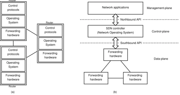
Software-defined networking is a new paradigm which revolutionizes net-work architecture through the introduction of a software-controlled, pro-grammable forwarding plane. Traditional networking devices are typically autonomous in nature. Each device hosts its own operating system, runs distributed control-plane protocols and builds a local network state. The op-erating system, which is often proprietary, consults the local network state and configures specialized forwarding hardware through proprietary applica-tion programming interfaces (API) [40]. SDN, on the other hand, eliminates these control-plane operations from network devices and moves the operating system to a logically centralized controller, also referred to as the network operating system. The controller exposes the network state learned from the
Forwarding hardware Operating System Control protocols Forwarding hardware Forwarding hardware Forwarding hardware SDN controller
(Network Operating System)
Forwarding hardware Operating System Control protocols Forwarding hardware Operating System Control protocols Network applications Data-plane Control-plane Management-plane (a) (b) Southbound API Northbound API Router Router Router
Figure 2.1: (a) Traditional network and (b) SDN network
forwarding devices to software-basednetwork applications. Routing decisions are made by the applications and communicated to the controller, which in turn translates these decisions in to forwarding rules and programs the ap-propriate devices. Forwarding devices then perform packet header matching against these rules to determine the port on which to send a packet out.
Communication between the network applications and the controller oc-curs over so called northbound APIs. Communication between the controller and forwarding devices occurs over southbound APIs. The forwarding de-vices constitute the data-plane, the controller constitutes the control-plane, and the networks applications form the management-plane [69]. Fig. 2.1 de-picts the difference between traditional networks and SDN networks.
SDN can also be defined in terms of three abstractions: forwarding ab-straction, distribution abab-straction, and specification abstraction [69, 98].
• Theforwarding abstraction allows network applications to make routing decisions without knowing any details of the underlying hardware. This is achieved through the use of open and standardized protocols for the communication with the forwarding devices.
• The controller implements the distribution abstraction. This abstrac-tion is essentially responsible for two tasks. First, it is responsible for installing forwarding rules on the network devices. Secondly, it gathers
Switch 1 Switch 2 Switch 3
Hosts Hosts Hosts
Controller
Switch 1 Switch 2 Switch 3
Hosts Hosts Hosts
Controller Control-plane
Data-plane Control + data plane
(a) (b)
Figure 2.2: (a) Out-of-band and (b) in-band control plane
information about the forwarding layer and exposes this state informa-tion to network applicainforma-tions thereby allowing them to build a global network view.
• Thespecification abstraction allows network applications to express de-sired network behavior without being responsible for the actual imple-mentation of the behavior itself.
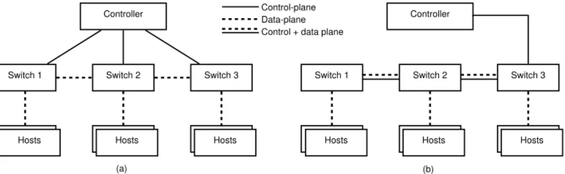
Physical connections between the forwarding devices and the controller can be set up in two ways: band and in-band [16]. In the out-of-band scheme, each forwarding device has a dedicated physical connection to the controller whereas in the in-band scheme, control-plane information is carried over existing data-plane connections between the forwarding devices. These scenarios are depicted in Fig. 2.2. Note that forwarding devices as referred to as switches which in computer networks terminology are typically layer-2 devices. In the context of SDN, a switch is a forwarding device which performs packet header matching regardless of the layer to which the header belongs; for instance forwarding can be based on layer-2 MAC addresses, layer-3 IP addresses, layer-4 port numbers, or a combination of all these fields. In SDN literature, the forwarding devices are nevertheless called switches as a reference to the single forwarding function that they perform.
SDN offers network operators many advantages. Decoupling the control and data planes allows the forwarding devices to be manufactured at lower costs since they no longer require the computing intelligence to perform control-plane processing [16]. The centralized control allows the controller to maintain an up-to-date view of the full network topology. The expos-ing of this network state to software applications enables better informed forwarding decisions [69]. Softwarization of the forwarding decisions accel-erates innovation and service creation. Network operators no longer need to wait for standardization and implementation of new protocols. Instead, new functionality can be deployed as plug-and-play software modules [66].
2.2
Network sections
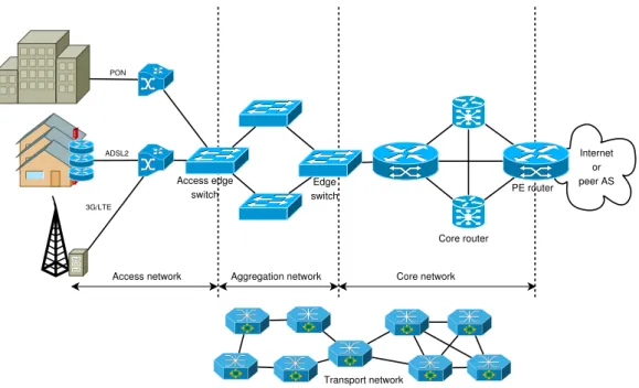
An operator’s telecommunication network is typically structured into the access network, aggregation network and core network [70]. These networks operate on packets of data which represent layer-2 and above of the network protocol stack. The data is carried over the transport network, which consists of optical switches and optical routers, and represents the physical layer (layer-1). These network sections are depicted in Fig. 2.3.
• The access network, as the name suggests, is part of the network that provides homes and enterprises with access to network services such as voice, video and data. Access technologies include xDSL (e.g. ADSL2, VDSL), optical access (e.g. PON, point-to-point fiber) and wireless (e.g. 3G, LTE). Connections from end-users terminate at an Ethernet switch, which we refer to as the access edge switch. It represents the first point of entry for user traffic in to the operator network.
• The aggregation network provides traffic aggregation from the access network. It consists of layer-2 Carrier Grade Ethernet and an under-lying optical transport network (OTN). Typically, the logical network topology is a tree-like arrangement of Ethernet switches [70], which are physically interconnected via metro or region OTN rings [9]. The aggre-gation network uses VLAN or Multiprotocol Label Switching (MPLS) based technologies to route the traffic to the core network [11, 84].
• Thecore network constitutes a layer-3 IP-MPLS backbone. The logical topology is typically a partial mesh network and the underlying OTN can be a ring or full mesh network [9]. We refer to the border node which interfaces with the global Internet or other peer networks as a
provider edge (PE) router.
2.3
Public key infrastructure
Public key infrastructure is a set of technical mechanisms, procedures and policies that collectively enable deployment of security services [106]. PKI is built on public key cryptography and digital certificates. Trusted nodes known as Certificate Authorities (CA) issue digital certificates to clients of the PKI (a human user, a server or a client machine). This allows clients to learn other clients’ public keys securely. This is achieved as follows. The CA typically has a self-signed certificate, i.e., the issuer and subject fields of the certificate are the same and contain the CA’s distinguished name. The
Internet or peer AS PON ADSL2 3G/LTE Access edge switch PE router Core router
Access network Aggregation network Core network
Transport network Edge
switch
Figure 2.3: Network sections in a telecommunication network
public key field contains the CA’s public key and the certificate is signed with its private key. A client certificate issued by the CA contains the client’s distinguished name in the subject field and the CA’s distinguished name in the issuer field. The client’s public key is inserted in the public key field and the certificate is signed with the CA’s private key. In this way, a digital certificate creates a mapping between names and public keys [89]. Fig. 2.4 depicts the fields and their values as described above.
Now let us assume Alice wants to prove her identity to Bob. In order to do so, Alice presents her CA-issued certificate to Bob. We assume that Bob trusts this CA and possesses a copy of the CA’s certificate (and thereby
Subject: CA name Issuer: CA name
Public Key: CA public key Signature: with CA private key
Subject: Client name Issuer: CA name
Public Key: Client public key Signature: with CA private key
(a) (b)
the CA’s public key). When Bob verifies the signature on Alice’s certificate using the CA’s public key, he can be sure that the correct CA (the one he trusts) has issued the certificate. Consequently, he trusts Alice’s public key. In a PKI, registration authorities are used to offload some of the work handled by CAs. However, for simplicity we omit them from our discussion. A more detailed discussion on PKI can be found in [65] and [24]. In the following sections, we introduce the PKI model used in this thesis and provide an overview of certificate management protocols.
2.3.1
PKI model
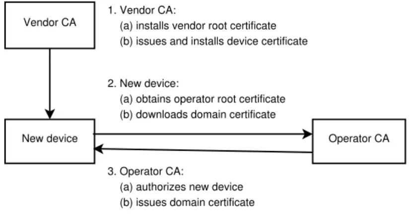
The PKI model considered in this thesis consists of the following actors and certificate profiles (depicted in Fig. 2.5):
• Vendor CA – The vendor CA is controlled by the manufacturer of the network equipment. It has a self-signed certificate which we refer to as the vendor root certificate. It issues a device certificate to every manufactured device. The vendor is responsible for installing both the vendor root certificate and the device certificate on the manufactured devices.
• Operator CA – The operator CA is controlled by the network operator and has a self-signed certificate, which we refer to as the operator root certificate. The operator CA is responsible for making decisions to allow or reject a new device from joining the network domain. If the device is allowed to join the domain, it issues a domain certificate to the device.
• New device – This is the device that wants to connect to the network. It is pre-installed with the vendor root certificate and a device certificate. When a device wants to join the network, it first obtains a copy of the operator root certificate. Then it requests the operator CA to issue a domain certificate to itself.
We assume that the new device connects to other nodes (for instance, the SDN controller) which are under control of the same network operator, i.e. the common trust anchor for all devices is the operator CA. Furthermore, we assume these nodes have already been registered to the network and possess a copy of the operator root certificate and a domain certificate signed by the operator CA.
New device Vendor CA
Operator CA 1. Vendor CA:
(a) installs vendor root certificate (b) issues and installs device certificate
2. New device:
(a) obtains operator root certificate (b) downloads domain certificate
3. Operator CA:
(a) authorizes new device (b) issues domain certificate
Figure 2.5: PKI actors and certificate profiles
2.3.2
Certificate management protocols
Certificate management protocols are used to support online exchanges of messages between clients and the CA in order to facilitate functions such as certificate enrollment, certificate revocation, key pair update, and key pair recovery. Several certificate management protocols have been developed over the years. The effort has mainly been driven by the Internet Engineering Task Force (IETF) Public Key Infrastructure X.509 working group and has been realized in the form of two management protocols – Certificate Manage-ment Protocol (CMP) [13] and Certificate ManageManage-ment Messages over CMS (CMC) [96]. The basic functionality of these two protocols is essentially the same [6] although CMP is the more comprehensive and widely deployed pro-tocol of the two. In addition to these propro-tocols, Cisco has developed the Simple Certificate Enrollment Protocol (SCEP) [90]. Despite being an Inter-net draft for almost a decade, the protocol has seen widespread deployment. In this section, we discuss how the CA can automatically authorize client certificate requests. In order to do so, CMP and SCEP make use of an out-of-band shared secret, referred to as the challengePassword in SCEP and the initial authentication key in CMP. The CA generates a shared secret and saves a binding between the secret and the requesting client’s name. The shared secret is communicated securely to the client before it makes the request.
In SCEP, the entire request is encrypted using the CA’s public key and the challengePassword is included. Upon decrypting the request and comparing the challengePassword with its database, the CA authorizes the certificate request if the passwords match. In CMP, the initial authentication key is used to protect the certificate request. If the CA is able to verify the message hash using its own copy of the initial authentication key, it can then automatically
authorize the request.
Both protocols also provide mechanisms to automatically authenticate the clients based on certificates issued by other CAs; for instance, the operator CA can authorize a device based on the device certificate. However, a trust relation between the operator CA and the vendor CA must be established in advance. Using device certificates to automatically authorize devices is not sufficient as one vendor may sell devices to several operators. Hence the operator must provision a white-list of the devices that are allowed to connect to its network. After successful verification of the device certificate, the CA consults the white-list, ensures that this device is allowed to join the network and only then authorizes the certificate request.
2.3.3
Motivation for using digital certificates
IP Security (IPSec) [50] and Transport Layer Security (TLS) [41] are the most notable protocols used for securing communication in the Internet today [15]. Both protocols support authentication through pre-shared keys (PSKs) as well as digital certificates.
A PSK is a string known by both communicating end-points. The PSK is never actually transmitted over the network; rather it is used to derive the keying material for the session. Configuring secure communication with PSKs is easier than with digital certificates as digital certificates require an associated public key infrastructure. However, digital certificates are con-sidered a stronger authentication method [81] and are also a more scalable authentication solution [7]. In a PSK scheme, the server needs to maintain a mapping between the user and the PSK for every user. This is not required in the digital certificate scheme. Unlike with PSK, a digital certificate’s creden-tials can be revoked by placing them on certificate revocation lists (CRLs). A certificate placed on the revocation list is no longer valid and the owner can no longer authenticate itself with this certificate.
In the rest of this thesis, we consider only digital certificate based schemes for securing communication.
2.4
Southbound protocols
Southbound interfaces enable the separation of control and data planes in SDN networks. They include the communication protocol that forwarding devices and the controller use to interact. Currently, considerable effort is being spent on standardizing these protocols to promote openness and inter-operability [69]. OpenFlow [83] has emerged as the predominant southbound
protocol. In addition to OpenFlow, several existing protocols such as PCEP [109], BGP [92] and NETCONF [46] can, with suitable modifications or ex-tensions, also be used as southbound protocols. It is worth mentioning here that networks are likely to support several protocols simultaneously.
In this section, we introduce some southbound protocols. We do not provide an exhaustive list and limit the discussion to protocols well suited to operator networks. Section 3.5 discusses the use cases and deployment models of these protocols.
2.4.1
OpenFlow
OpenFlow was first proposed by McKeown et al. [83] in 2008 and has since then gained industry-wide importance. Several versions of the OpenFlow specifications have been released, the latest version being 1.5.0 released in January, 2015. New versions of OpenFlow add new features to improve the protocol but the inherent methods to program the forwarding devices remain more or less the same.
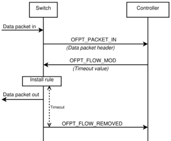
An OpenFlow switch performs packet forwarding by consulting its flow table to determine the output port on which to send the packet. Each entry in the flow table (called a flow rule or flow entry) consists of the packet header fields to match, the actions to apply on matching packets, and the corresponding counters to update. When a switch receives a packet which cannot be matched to any installed flow rule the switch typically first buffers the packet and then requests a new flow rule from the controller with an OFPT PACKET IN message. This message includes the packet’s header fields. The controller then responds with an OFPT FLOW MOD message, which contains a rule for handling the packet and the duration for which to keep the flow rule in its flow table. This duration is called a timeout. Each flow rule has two associated timeout values, an idle timeout value (or soft timeout), which is triggered when the flow remains inactive, and a hard timeout, which is triggered regardless of the flow’s activity. When either of these timers expires, the switch removes the corresponding flow entry from its flow table and sends an OFPT FLOW REMOVED message to the controller. This mechanism of flow rule installation is reactive (depicted in Fig. 2.6) meaning that rules are requested by the switch only upon receiving data packets. Controllers may also behave proactively by installing rules to handle expected data traffic [25] along the path of a flow when the packet is seen at the ingress switch.
As mentioned above, when a switch first receives a packet belonging to a new flow, it buffers the packet before sending an OFPT PACKET IN mes-sage to the controller. This mesmes-sage includes a maximum of 128 bytes of the
Switch Controller
Data packet in
OFPT_PACKET_IN
(Data packet header)
OFPT_FLOW_MOD
(Timeout value)
Install rule Data packet out
OFPT_FLOW_REMOVED
Timeout
Figure 2.6: Reactive flow installation in OpenFlow
Switch Controller
Data packet in
OFPT_PACKET_IN (Data packet header + data)
OFPT_PACKET_OUT Data packet out
(Data packet header + data)
Figure 2.7: Behavior when switch cannot buffer packets
received packet header. However, if the switch does not have buffering capa-bilities or if the input buffer is full, the OpenFlow specification [5] mandates the switch to send the entire packet to the controller encapsulated within the OFPT PACKET IN message. In this case, the controller responds with an OFPT PACKET OUT message which also includes the entire data packet. No flow rule is installed and the switch simply performs the associated ac-tion (which is typically to forward the packet out on the specified port). This scenario is depicted in Fig. 2.7.
OpenFlow also provides additional methods such as those used to ex-change capability information (e.g. supported version of the protocol), port status information (e.g. when a port comes up or goes down), and error messages (e.g. when a flow rule addition fails).
2.4.2
Path computation element
communication protocol (PCEP)
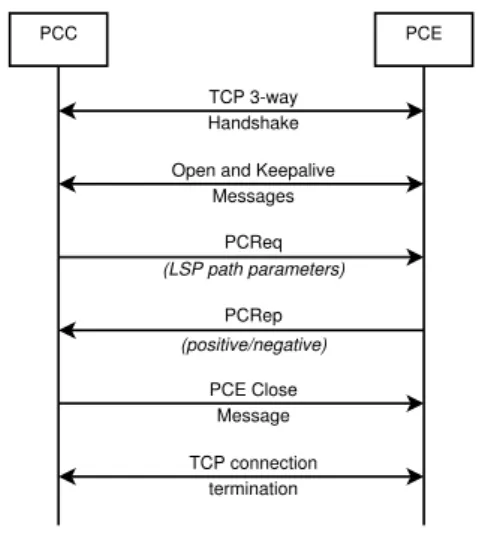
PCEP [109] was designed to enable simpler and more efficient MPLS and GMPLS path computation in large, multi-domain networks. The main idea is to decouple path computation from network devices, and move the func-tionality to dedicated entities with communication occurring over a stan-dardized protocol. The network devices are referred to as Path Computation Clients (PCCs), path-decisions are made by the Path Computation Element (PCE), and the communication protocol is called PCEP. Fig. 2.8 shows the normal call-flow between the PCC and the PCE. The diagram depicts a pas-sive PCE, wherein a path is computed based on a received request. The PCC sends to the PCE the Label Switched Path (LSP) path parameters which may include the source IP address, the destination IP address, and the required bandwidth. The PCE either replies positively and provides the MPLS label to be used for the path, or it can reply negatively, for instance, if the requested bandwidth is unavailable. PCEs may also behave actively by installing paths dynamically when network changes are detected. Further-more, PCEs can be stateless or stateful. Stateless PCEs do not maintain a database of allocated resources and hence may create suboptimal paths.
TCP 3-way Handshake Open and Keepalive
Messages TCP connection termination PCReq PCRep PCE Close Message PCC PCE (LSP path parameters) (positive/negative)
Figure 2.8: A PCEP session
2.4.3
Interface to routing system (I2RS)
Routers build their Routing Information Base (RIB) by participating in in-terior and exin-terior gateway routing protocols. This database is built solely
from control-channel communication with other nodes. Based on the learned topology, routers populate their Forwarding Information Base (FIB), which the data-plane references to perform packet-matching and forwarding. As discussed in Section 2.4.1, OpenFlow allows programming the FIB. I2RS [1], on the other hand, is an effort to standardize interfaces and data models to allow programmability of the RIB. The proposed architecture includes I2RS-Agents, I2RS-Clients and I2RS-Services [18] as depicted in Fig. 2.9. Agents run on network devices and provide services such as accessing the RIB manager and topology database. Applications access services through I2RS-Clients. The protocol for communication between the client and the agent is the I2RS protocol. I2RS is work in progress and there are no official standards proposed yet. However, the IETF’s I2RS working group is driv-ing an effort to standardize a data model, which can be used to define an interface to the network device’s RIB [20].
Application Application I2RS-Client Application I2RS-Client I2RS-Agent Policy database Topology database FIB manager and data plane Subscription and
configuration templates for measurements,
events, QoS, etc.
RIB manager Routing and signalling protocols I2RS Protocol Other I2RS-Agents
within scope of I2RS Protocol not within scope of I2RS Protocol router boundary
2.4.4
BGP flow-spec
BGP flow-spec [80] is an extension to the Border Gateway Protocol (BGP) to enable dissemination of traffic flow-specifications (flow-spec) to BGP peers. RFC 5575 defines a new BGP Network Layer Reachability Information (NLRI) address family. This NLRI allows encoding flow-specifications using the multi-protocol extensions for BGP [21]. A flow-specification rule is like an access control list (ACL) rule and consists of the criteria to match aggregated traffic flows based on elements such as the IP destination prefix, IP source prefix, and layer-4 port numbers. The actions to apply to matched flows include accept, discard, rate-limit and redirect and they are specified in the extended communities attribute [58] of the BGP message. In the context of SDN, the controller may act as the flow-specification originator and update policies dynamically on the network devices. The network devices can then propagate this information to other BGP peers within the operator’s network or to another operator’s network depending on the applied configuration.
2.4.5
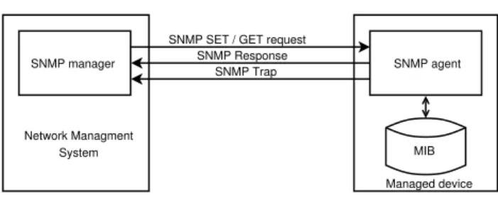
Simple network management protocol (SNMP)
SNMP was first conceived in 1988 and has since then undergone several revisions, the latest being SNMPv3 [32]. The SNMP architecture follows a manager-agent model. The manager resides on the Network Management System (NMS) and issues SET or GET requests to an agent running on the managed device. The agent interacts with the device database, known as the Management Information Base (MIB), and carries out the desired task. Additionally, agents can also notify the manager on occurrence of certain events through messages called SNMP traps.
Managed device Network Managment
System
SNMP manager SNMP agent
MIB SNMP SET / GET request
SNMP Response SNMP Trap
Figure 2.10: SNMP
SNMP is a widely recognized protocol and is implemented extensively across all sorts of network devices. Although SNMP is a good candidate for a southbound interface, it has several practical shortcomings. These are discussed in [99] and include the following:
• SNMP performance of reading large amounts of data (such as router’s routing table) is very poor.
• Network administrators view configuration of devices as a task se-quence. However SNMP’s view is data-centric wherein configuration implies changing state of data objects. Hence, there is a need for addi-tional translation code on the management application.
• Writeable SNMP objects are not widely deployed. Furthermore, stan-dard MIB modules do not always provide the writeable objects that would be needed for SDN. Many such objects are contained only in proprietary modules. Therefore SNMP cannot easily be used to pro-gram forwarding rules on the network devices.
2.4.6
NETCONF
NETCONF was developed by the IETF to address the shortcomings of SNMP. Like SNMP, it is a network management protocol and “provides mechanisms to install, manipulate, and delete the configuration of network devices” [46]. The NETCONF protocol is divided into four layers as depicted in Fig. 2.11. Messages and configuration data exchanged between the NMS (or client) and the network device (or server) are encoded using Extensible Markup Language (XML) [28]. The protocol operations are carried out as Remote Procedure Calls (RPCs).
Secure Transport Messages Operations Content SSH, TLS, BEEP/TLS, SOAP/HTTP/TLS, ... <rpc> <rpc-reply> <edit-config> Configuration Data <notification> Notification Data Layer Example (1) (2) (3) (4)
Figure 2.11: NETCONF protocol layers [46]
(1) The Secure Transport layer provides a communication path between the client and the server. NETCONF requires this connection to be per-sistent, connection-oriented and provide authentication, data integrity,
confidentiality, and replay protection. NETCONF implementations are required to support the SSH protocol.
(2) The Message layer provides mechanisms to encode the RPCs and no-tifications in a transport-independent manner.
(3) The Operation layer specifies a set of operations to manage devices and retrieve state information. Some examples include get, get-config, edit-config, lock, and close-session. The operations may be extended depending on the device’s capabilities.
(4) The Content layer is needed to model the configuration and state data of the devices. NETCONF itself does not provide such a model. YANG [27] has emerged as the leading data-modelling language to be used in conjunction with NETCONF.
NETCONF is a proven standard for writing network configurations. Its features include domain-specific knowledge, support for transactions, and vendor independence. NETCONF can be used to configure the devices through the edit-config operation. Thus it enables programmability of the forwarding devices. NETCONF is the configuration protocol used by OF-CONFIG [4] to program OpenFlow devices.
2.5
Protocols for topology discovery
Topology discovery involves learning how network devices are interconnected. The discovered topology can represent either logical or physical connections. A logical view of the topology is constructed from layer-3 information. With this method, layer-2 devices are not discovered [23]. It only determines con-nections between devices without knowing details of the physical links. On the other hand, a physical view of the topology is constructed using layer-2 mechanisms and this method exposes the physical interconnections between devices. Peers in the logical topology are routers that are one hop from each other, whereas peers in the physical topology are directly connected ports [105]. Topology discovery is a crucial component in SDN networks as network applications depend on this information to make routing deci-sions. Furthermore, applications need to know about the complete network topology in order to make optimal routing decisions.
In this section we introduce some of the protocols used for topology dis-covery in conventional networks. The same protocols can be used for topology discovery in SDN networks as will be explained in Section 3.4.
2.5.1
Simple network management protocol (SNMP)
SNMP has been presented in Section 2.4.5 as a southbound protocol. It can also be used for the purpose of topology discovery. As previously mentioned, devices with SNMP support store all information in Management Information Bases (MIB).
The information on the devices is keyed by hierarchical Object Identifiers (OIDs). There are both standard and proprietary MIBs. As an example of an OID, the BGP version of a node is represented asiso(1).org(3).dod(6).internet(1). mgmt(2).mib-2(1).bgp(15).bgpVersion(0) or simply 1.3.6.1.2.1.15.1.0. The value returned by an SNMP query with this OID will be 4 if the IPv4 ver-sion of the BGP protocol is being used by the queried device.
Other information stored as OIDs includes details regarding the device’s ports and the neighbors to which it is connected. Control-plane protocols such as IS-IS [59], OSPF [36, 85] and BGP [92] have standardized MIBs [54, 63, 88]. By querying each device with the SNMP GET method, topology information can be extracted from the devices and then pieced together to form a complete view of the network topology.
2.5.2
Link layer discovery protocol (LLDP)
LLDP1 was standardized by the IEEE in the standards document 802.1AB
[10]. As the name suggests, it is a link-layer (layer-2) neighbor discovery pro-tocol that enables adjacent switches to identify each other and exchange infor-mation regarding their capabilities. The protocol was developed to supplant proprietary protocols, such as the Cisco Discovery Protocol and Extreme Discovery Protocol, and hence it was designed to work in a multi-vendor environment.
LLDP works in two modes, the transmit mode and receive mode. In the transmit mode, a switch periodically sends out Ethernet frames called LLDP Data Units (LLDPDU) from each of its interfaces. Each LLDPDU contains the switch identifier and the identifier of the port from which the frame is sent. The destination MAC is set to a special multicast address. Upon receiving an LLDPDU (in the receive mode), a switch parses the LLDPDU and stores the switch identifier and port identifier in to the Physical Topology Management Information Base (PTOPO-MIB) [26]. Devices are required to consume the LLDPDU, i.e., they should not forward it to any other port [8]. LLDP allows switches to exchange information with their adjacent nodes, and hence they are able to learn only about their immediate neighbors. A
1LLDP is formally referred to by the IEEE as Station and Media Access Control
system administrator can, via the network management system and SNMP, retrieve a switch’s PTOPO-MIB [26]. By querying all the switches in the network and thus gathering each switch’s neighbor information, the entire network’s physical topology can be constructed.
2.5.3
BGP link-state (BGP-LS)
With interior gateway routing protocols (IGP), such as OSPF and IS-IS, the network devices’ topology knowledge is limited to the area or domain to which they belong to. Although it is possible to make the SDN controller a passive IGP listener and thereby obtain topology information, this method does not scale well. The controller needs to participate in the IGP at several areas and piece together the gathered information to form the full network topology. BGP-LS [52] has been proposed as a solution to this.
BGP-LS is an extension to BGP enabling it to carry link-state informa-tion gathered by the IGPs. A BGP message contains one or more Link-State NLRIs, which are further classified as Node NLRIs, Link NLRIs and Prefix NLRIs. A Node NLRI uniquely identifies the router, a Link NLRI uniquely identifies a link, and a Prefix NLRI uniquely identifies an IPv4 or IPv6 Pre-fix originated by the BGP speaker. Each domain must have at least one BGP speaker and the IGP information is redistributed to this node. The SDN controller (or another dedicated network node with which the con-troller interfaces) can act as a BGP route reflector, and thereby learn the entire network’s topology. This scenario is depicted in Fig. 2.12.
Domain 1 (OSPF) BGP-LS Domain 2 (IS-IS) BGP-LS Domain N (Multi-area IS-IS) BGP-LS BGP-LS route reflector SDN controller
SDN deployment solutions
This chapter presents our survey and analysis of deploying SDN in telecom-munication networks. To build a new network or to upgrade an existing one, the operator needs to determine the services that it wants to provide, analyse the associated network requirements, and procure the network equipment. The operator then needs to work out a deployment strategy and begin in-stalling the devices in the network. Each installed device must be configured with a management interface and have the appropriate protocols enabled. In addition, the operator must configure the mechanisms and access rights for performing network management tasks such as traffic engineering, network monitoring, and troubleshooting. These jobs are quite diverse and automat-ing them is crucial in order to be able to scale the deployment process and enable ease of management.
In this chapter, we discuss some of these deployment considerations in the context of SDN. We broadly classify them as follows:
• Setting up new hardware – strategies for transitioning to an SDN net-work
• Bringing up a device – connecting a device to the network
• Bootstrapping security – provisioning security keys and configuration on the device to enable secure control-plane communication
• Performing topology discovery – constructing a view of the network’s physical topology
• Packet forwarding – southbound protocols and network applications for installing packet forwarding rules
3.1
Setting up new hardware
In order to reap the benefits of SDN, network operators first need to install programmable network devices in the network. A straightforward strategy is to simply swap-out existing network devices and replace them with SDN devices. This approach is viable when rolling out a new network or deploying SDN in closed environments such data-centers and campus networks [101]. For example, such aclean-statestrategy was employed by Google in deploying their inter data-center SDN network [60]. However, the deployment took several years and the benefits were visible only after the entire switching hardware was upgraded [72].
A complete network overhaul is not always a feasible solution. Network operators want to protect their current investments, and budget constraints may restrict purchase of large volumes of new equipment at one time. Hence, another approach is to deploy SDNincrementally alongside the existing net-works. We call a heterogeneous network with legacy hardware and SDN hardware a hybrid network.
Another possibility to deploy SDN incrementally is through a dual-stack
approach, wherein a network device runs both legacy protocols and SDN pro-tocols in parallel. We call such a device ahybrid switch. The implementation of a hybrid switch can be twofold. In the basic hybrid switch, packets tagged with certain VLAN tag numbers are processed by SDN methods whereas other packets are handled by traditional methods. A variant of the hybrid switch method, which is gaining popularity due to its inclusion in the Open-Flow 1.3 specification [5], is one where the forwarding pipeline supports both traditional processing and SDN processing. In such an implementation, the controller maintains control over all the switch ports and VLANs. By insert-ing appropriate rules in the forwardinsert-ing table, the controller delegates control decisions to the switch itself. For instance, the controller may install a rule to forward all DNS requests to it for inspection but instruct the switch to handle all other traffic in the traditional way. In this manner, the controller (and network applications) can be light-weight modules that know only about DNS and not any other kind of traffic. Furthermore, not all traffic needs to be forwarded to the controller, thereby saving computing resources and network bandwidth. The main advantage of the dual-stack deployment is that this method allows for an overnight change in the forwarding hardware. When a hybrid switch is installed in the network, the controller instructs it to handle all traffic in the traditional way. Thus, it leads to a seamless transition to an SDN-ready network where SDN functionality can slowly be switched on. Fig. 3.1 depicts the three deployment strategies discussed in this section.
SDN controller SDN controller Applications Applications SDN controller Applications (a) (b) (c) SDN-enabled device Legacy device Hybrid device
Figure 3.1: SDN deployment models (a) clean-slate (b) hybrid network (c) dual-stack
3.2
Bringing up a device
Bringing up a network device involves providing IP connectivity to the device and enabling remote management of the device. In this phase of deployment, the device behaves as an end-host rather than as a forwarding device, i.e., the device cannot forward any packets yet. We assume the device supports the normal networking stack and protocols that are supported by end-hosts; for example the Dynamic Host Configuration Protocol (DHCP) and Domain Name System (DNS). The initial configuration operation can be performed manually using the Command Line Interface (CLI) or in an automated man-ner. In this section, we discuss the configuration parameters and associated network infrastructure required to connect a device to the network.
3.2.1
Enabling IP connectivity
When manually bringing up the device, an engineer present at the installation site performs the initial configuration tasks. The engineer connects one end of a serial cable to a laptop and the other end to the console port of the device and starts a terminal emulation software on the laptop. Now the device is ready to be configured through vendor-specific CLI instructions. The first step is to enable IP connectivity by configuring one or more interfaces with IP addresses. A layer-2 switch has only a virtual interface associated with an IP address. A layer-3 router has an IP address configured on each of its
physical interfaces in addition to one or more virtual interfaces. Furthermore, the address of the default gateway router, DNS server, network time protocol server, and the device host name are also configured on the device.
Alternatively, the device can obtain some or all of the mentioned config-uration parameters via DHCP [45] and BOOTP vendor extensions [14]. The process of automatically enabling IP connectivity is depicted in the form of a flow chart in Fig. 3.2. The operator must set up the DHCP server before the device starts the DHCP protocol. A reservation (mapping of DHCP pa-rameters to a specific device) should be added on the DHCP server based on either the MAC address of the interface or device client identifier which will be included in the DHCP request. This is required so that the DHCP server can allocate to the device the correct host name and the Trivial File Transfer Protocol (TFTP) server address from which to fetch subsequent configuration. In case the host name is not learned via DHCP, the device performs a reverse DNS lookup on the IP address it received via DHCP and thus learns its host name. This means that the DNS server must also be set up in advance and should be reachable from the device. Alternatively, there may be a file on the TFTP server containing a mapping of the host name and IP address. The device downloads this file and chooses the correct host name. For the device and DHCP server to communicate over DHCP, the DHCP server should reside on the same LAN as the device. If this is not the case, there should be a DHCP relay agent which forwards requests and replies between the device and the DHCP server.
Device powered-on
Assigned IP, TFTP server address
via DHCP and BOOTP
DHCP offer included hostname? Reverse DNS lookup to learn hostname Reverse DNS successful? TFTP server provided host-IP mapping? Use learnt hostname to
fetch device configuration from TFTP server Enabling IP connectivity successful No No Yes Yes Yes Obtained configuration? No Enabling IP connectivity failed No Yes
3.2.2
Enabling Remote Management
For remote management of the device, Telnet and/or SSH need to be enabled. This may be configured manually or may be part of the initial configuration file downloaded from the TFTP server. Telnet can be used when connecting to the device from within an isolated secure environment. However, Telnet offers no encryption or server authentication. Also, when a Telnet connec-tion is made, the user name and password are sent in clear text over the network. Since the device does not know what kind of environment it is in, Telnet should be disabled by default. SSH is the most commonly used secure remote login protocol and provides public-key based authentication as well as password-based authentication. Password-based authentication requires the allowed user name and password to be provisioned on the device, for example, as a part of the initial configuration file. However, as discussed in Section 2.3.3, this method is not as secure as the public-key authentication methods and does not scale well. For public-key authentication, the device needs to generate a key pair. This can be triggered manually through the CLI, or the device itself can generate keys at the first boot up. The keys, once created, are stored in the device’s non-volatile memory.
3.3
Bootstrapping security
The most popular secure communication protocols, namely TLS/SSL and IPSec, use digital certificates for authentication. In this section we discuss mechanisms for:
(a) installing the operator root certificate
(b) provisioning a domain certificate signed by the operator CA
Please refer to Section 2.3 for details on the PKI actors and certificate profiles.
3.3.1
Installing the operator root certificate
Each network device needs the operator root certificate in order to verify the domain certificates presented by the SDN controller and other devices to which it connects. It also uses the operator root certificate to verify the authenticity of its own domain certificate during enrollment. The operator root certificate can be installed on the device through the CLI or by installing it from a USB disk. This method is secure as long as only authorized indi-viduals have access to the CLI of the device. Alternatively, the device itself
can download the required certificate directly from the CA or another public certificate repository. The device needs to be provided with the URL from where to download the certificate. However, manual intervention is required to verify the authenticity of the certificate. The device or the device ad-ministrator must compare the fingerprint of the received certificate with an authentic fingerprint received by out-of-band methods. This fingerprint can also be pre-configured on the device, in which case the interactive verification of the certificate is no longer required. Fig. 3.3 depicts the steps to install the operator root certificate.
1. Provide:
(a) Operator root certificate fingerprint (b) Certificate Repository URL
2. Request operator root certificate
3. Provide requested certificate
4. Verify fingerprint
Device Certificate Repository
Figure 3.3: Installing the operator root certificate
3.3.2
Provisioning a domain certificate
The device can register with the network through a manual process or in an automated manner. The basic steps (depicted in Fig. 3.4) involved are as follows:
1. Device creates a certificate signing request (CSR) and sends it to the operator CA
2. Operator CA authorizes the request
3. Operator CA creates a signed domain certificate and makes it available to the device
We first assume that the device has had no prior contact with the PKI system and owns no digital certificates, i.e., it does not possess even a device certificate. Additionally, we assume that the device has a key pair which it wishes to have certified by the CA. In the manual mode, an engineer generates a certificate signing request by entering CLI commands. The engineer then transfers this request to the CA by any appropriate method, for example,
by email, in a file, or with a copy-paste operation from the user interface. The engineer must ensure that the request is transferred to the CA without possibility of malicious modification and then manually authorize the CA to issue the certificate. If the CA accepts the request and generates a certificate, the engineer again transfers and installs the certificate onto the device.
In an automated method, the device uses certificate enrollment protocols such as SCEP or CMP to obtain the digital certificate. In order to authorize the request, the CA generates a password and creates a binding between the device and the password. This operation is manually performed and the password is configured on the device using out-of-band methods. The certificate request is authenticated using this shared secret and hence the CA can automatically authorize the request. There is no need for the device to authenticate the CA as that can be done once the digital certificate has been received. The device can verify if the expected CA created the certificate by verifying the signature on the issued certificate.
When the device possesses a digital certificate signed by a third-party CA (such as the vendor CA), authorization can be simplified (refer to sec-tion 2.3.2). The operator CA can authorize requests based on the device certificate presented by the device. However, one vendor may sell network devices to several operators. So the operator needs to configure a white-list with the serial number of the devices that are allowed to join the network. Upon receiving a request, the CA checks this list for the presence of the serial number and then proceeds to authenticate the device. In this case, the CA needs to have a list of the trusted vendor root certificates in order to verify the device’s identity.
2. Send CSR
4. Provide domain certificate
5. Verify received certificate Device CA 1. Create Certificate Signing Request (CSR) 3. Authorize CSR and grant request
3.3.3
Bringing up a remote device outside the secure
operator network
A network device, for example one that is located in the access network, may need to connect to the servers (e.g. the SDN controller) located in the secure operator network over an insecure public Internet. In order to bring up the device from such an insecure environment, all control-plane communication with the device must be protected. IPSec is a suitable protocol for such an environment as it enables encryption at the IP layer and thereby all traffic, regardless of the transport protocol or service, can be protected. In this case, the device first obtains an IP address via DHCP and also learns the IP address of the IPSec gateway for the trusted domain. Then the device performs certificate enrollment with the operator CA as discussed in the section above and obtains the domain certificates for IPSec authentication. It can then form an IPSec tunnel through the untrusted network and and connect securely to the other servers, for instance the TFTP server. If the operator CA resides within the secure operator network, appropriate firewall rules and policies must be configured on the IPSec gateway to allow traffic between the device and the CA before the device has formed an IPSec security association.
3.3.4
Enhanced security with logging servers
As discussed earlier, the DHCP server or relay must be located on the same LAN as the new device. Thus, if the new device is brought up in an untrusted network, the DHCP server or relay will also be located in the untrusted network. In this case, the device can be hijacked with a rogue DHCP server so that its deployment to the operator network fails. Hence, the network operator needs a mechanism to detect the successful or failed integration of the device into the operator domain. This can be achieved through the use of preconfigured event logging. We describe our assumptions and the functionality below.
1. The device allows only one domain certificate, i.e., the domain certifi-cate identifies the operator network to which the device is connected. We assume here that the device is controlled only by one network op-erator at a time.
2. The network equipment vendor knows which devices are sold to which network operator.
accounts and view the list of devices. In addition to providing the list of devices, the service also stores logs received from the device.
4. The device has fixed pre-configured fully qualified domain names for the logging servers.
5. The operator configures its DNS servers to resolve the IP addresses of these logging servers and its firewall to allow network devices to access them.
Once the device obtains IP connectivity, it periodically sends the logging servers its certificate details and the IP addresses of the SDN controllers to which the device is connected. By manually observing logs from the new device, the network operator can check whether the device has connected to its domain as expected. The operator needs to verify the device’s identity, the certificate issuer’s name and the details of the SDN controllers. If any of the information is wrong, the operator can reset the device and start afresh. On the other hand, if no events are seen on the logging server, it means that the device may have obtained false configuration information from DHCP and has been hijacked. Again, the device should be reset and the process started afresh. These scenarios are shown in Fig. 3.5.
Operator signs in to the log server and selects the device being bootstrapped
Logs from the device are visible? Faulty bootstrap or device hijacked Device reports correct certificate and controller details? Bootstrap successful Yes Yes No No No
Figure 3.5: Detecting bootstrap result from log server
We propose that there are at least two logging servers – one vendor con-trolled and the other operator concon-trolled. The vendor’s logging service may provide only a minimal service; for example the operator can list devices and view logs from the device. This allows the operator to rely on the vendor provided service initially, before the device has been configured to use the operator’s own logging service. Additionally, the vendor logging server can
make use of secure TLS connections through the use of device certificates. If the operator does not wish to expose device information to the vendor, the vendor’s logging service need not be resolved on the DNS server. Having an operator-controlled logging server allows the operator to create monitoring applications on top of the service. For instance, the logging server could send email notifications or SNMP traps if the state of the device changes.
3.4
Topology discovery
Discovering the complete physical network topology is crucial in SDN net-works as SDN applications require this information to make optimal routing decisions. However, as learned in Section 3.1, operators are likely to employ an incremental deployment strategy in which legacy and SDN devices need to interoperate. This section considers how the full topology of such net-works can be learned. In order to simplify the discussion, we first start with topology discovery mechanisms in pure SDN networks followed with those used in pure legacy networks. We then expand our discussion to the case of hybrid SDN networks.
3.4.1
Topology discovery in pure SDN networks
OpenFlow messages combined with the Link Layer Discovery Protocol (LLDP) can be used to construct the physical topology of pure SDN networks. We assume here that all the devices in the network speak the OpenFlow pro-tocol. To explain how discovery works we consider the simple topology as illustrated in Fig 3.6. Controller c0 Switch A Switch B 2 1 1 2
Figure 3.6: Simple topology to explain how link discovery works Upon initial connection establishment with each switch, the controller installs a flow rule to forward LLDP packets to it. It then crafts an LLDP packet containing its own controller identifier (c0) and the device identifier of the switch to which the packet is destined. Let us assume the packet is sent to switch A. The controller encapsulates the LLDP packet into a
PACKET OUT message and instructs switch A to flood the packet. Switch A then sends the LLDP packet out on all its data-plane ports, in this case only port 2. When switch B receives this packet, a rule match for LLDP is found. Switch B encapsulates the received packet into a PACKET IN message and sends it to the controller. The PACKET IN message includes the number of the port on which the LLDP packet was received (port 2 in this case).
The controller parses the packet and determines that it had initially sent this packet to switch A (based on the switch identifier). Hence it learns that port 2 of switch B is connected to some port of switch A. It repeats this process by sending an LLDP packet to switch B and when the same LLDP packet is received in the PACKET IN message from Switch A, the controller can learn that port 2 of switch A is connected to switch B. By combining these two pieces of information, the controller now determines that port 2 of switch A is connected to port 2 of switch B.
Controller c0 Switch A Switch B
OFPT_PACKET_OUT LLDP: cID="c0", sID="A"
LLDP: cID="c0", sID="A" OFPT_PACKET_IN (rPort="2", sID="B")
LLDP: cID="c0", sID="A"
OFPT_PACKET_OUT LLDP: cID="c0", sID="B"
LLDP: cID="c0", sID="B" OFPT_PACKET_IN (rPort="2", sID="A")
LLDP: cID="c0", sID="B"
Determine bidirectional link: port 2 of switch A connected to port 2 of switch B
Learn unidirectional link: port 2 of switch A connected to switch B Learn unidirectional link:
port 2 of switch B connected to switch A
Figure 3.7: Topology discovery using OpenFlow and LLDP
![Figure 1.1: Energy consumption of operator’s network [70]](https://thumb-us.123doks.com/thumbv2/123dok_us/10177535.2920096/14.892.317.576.188.404/figure-energy-consumption-of-operator-s-network.webp)
![Figure 2.9: I2RS architecture [19]](https://thumb-us.123doks.com/thumbv2/123dok_us/10177535.2920096/26.892.274.616.511.913/figure-i-rs-architecture.webp)
![Figure 2.11: NETCONF protocol layers [46]](https://thumb-us.123doks.com/thumbv2/123dok_us/10177535.2920096/28.892.270.622.718.931/figure-netconf-protocol-layers.webp)
