Using Fine-Grained Infrared Positioning
to Support the Surface-Based Activities of Mobile Users
Albert Krohn, Michael Beigl
Telecooperation Office
Unversit¨at Karlsruhe
Mike Hazas, Hans-Werner Gellersen
Computing Department
Lancaster University
Albrecht Schmidt
Institut f¨ur Informatik
Ludwig-Maximilians-Universit¨at M¨unchen
Abstract
Knowledge of the fine-grained location and orienta-tion of devices on a surface can be used to enhance the surface-based computing tasks of mobile users in the home and workplace. However, existing systems which provide surface-based positioning information are often not a prac-tical solution for mobile users, since the systems all rely upon pre-installed and calibrated environmental infrastruc-ture. In this paper, we present prototype positioning devices for surfaces which do not rely on such infrastructure. We show that inexpensive infrared transducers can be used to effectively sense relative location and orientation of surface devices. We evaluate the novel approach of using intensity of light pulses for fine-grained location measurements.
1. Introduction
In everyday living and working environments, people perform a large number of tasks on surfaces such as desks and tables. For mobile users, these surface-based tasks often heavily involve portable computing devices, ranging from laptops to mobile phones. During such tasks, the ability to configure wired and wireless connections between the de-vices can be crucial. For meetings and collaborative work, it is commonplace for multiple users to have several devices each, and to utilise some form of shared virtual workspace between the devices.
Such application scenarios can be greatly enhanced us-ing knowledge of the fine-grained location and/or orienta-tion of the devices on the surface. Current locaorienta-tion systems which can supply surface-based positioning data are thus inappropriate, since they rely on costly and labour-intensive installations of transducers and equipment in the environ-ment.
This paper presents a novel prototype system which al-lows users’ mobile devices to perform peer-to-peer sensing on a surface and compute their locations and orientations in a 2D space. We first outline specific surface-based ap-plications for mobile users, and propose infrared light as a fine-grained location sensing medium appropriate for their portable devices. We then detail our implementation and characterisation of the prototype system. Our findings show that such a system supports the positioning requirements of mobile users’ surface-based tasks.
2. Related Work and Motivation
This section first outlines applications which require the location and orientation of user devices placed upon sur-faces, such as desks and meeting tables. It is then demon-strated that current location technologies are inappropriate for mobile users and their portable devices. The choice of infrared as a fine-grained, 2D location sensing technology for these devices is then justified.
2.1. Surface-based activities of mobile users
Often, many devices are placed on a single working sur-face, including keyboards, monitors, laptops, PDAs, mobile phones, and digital cameras. Their relative positioning in-formation can be used to create GUI representations of the layout of the devices on the table. These allow the user to easily specify source and destination of data by perform-ing drag-and-drop actions between devices across the sur-face (hyperdragging) [2].
Configuring connectivity between devices is also ex-tremely important for mobile users who gather for team-oriented tasks, as shown previously [3]. Positioning infor-mation of the users’ portable devices, such as laptops, mo-bile phones, and PDAs, can be used to facilitate easy trans-fer of data objects between team members, as well as au-tomatic configuration of associations between devices. For example, using a laptop with a GUI representation of the de-vices on the table, one person can associate some data with a small, nearby device, making it a token for the data (sim-ilar in concept to the mediaBlocks presented by Ullmer et al. [4]). The token can then be handed to another group member, who can place it in close proximity to their own device to indicate that the system should transfer the data.
Alternatively, the token might represent a shared meet-ing resource, such as a projector. As the meetmeet-ing progresses the token can be passed between participants, each of whom can display content on the projector by placing the token near and pointing it toward their own device. A URL or file specified by the user possessing the token could then be transferred temporarily to the PC driving the projector, which then displays the data object. (In this way, the token would provide some of the functionality of the Meeting-Machine Remote Control, described by Barton et al. [3].) The projector token might also be placed in the centre of the meeting participants’ table, and then its orientation used to indicate the device which should control the content dis-played on the projector.
In modern devices, wireless communication such as Bluetooth or WiFi is often available. Achieving the above discussed applications is then only a matter of software. Most of the application scenarios described involve con-figuring connections and transfers between devices on the surface. Thus, the necessary positioning informa-tion provided to the applicainforma-tions need only be relative (referenced to the devices themselves) rather than abso-lute (referenced to the surface or the room). The positioning requirements of the applications discussed can be sum-marised as follows:
1. Location accuracy: between 10 cm and 20 cm, a granu-larity similar in size to the smaller devices which might be used (mobile phones and PDAs)
2. Orientation accuracy: about 30°, allowing detection of when devices are facing one another
3. Update rate: once every few seconds, providing ade-quate response time for configuring connections
4. Number of devices: up to twenty for large meetings or mobile users with many devices on a single surface
2.2. Existing location technologies
appropriate for surfaces
Certain indoor location systems for context-aware com-puting are able to provide fine-grained location and orientation information sufficient for applications on sur-faces [5, 6]. Systems have also been developed specif-ically for surface-based location sensing. These have used a number of techniques, including computer vi-sion [2, 7, 8], physical contact or weight [9, 10], optical mouse tracking [11], and short-range electromagnetic sig-nals [12].
The indoor location systems mentioned above accom-plish wide-area fine-grained tracking, while the majority of the surface-based systems have been designed for user in-terface scenarios which require centimetre resolution and many updates per second. As a result, many of these sys-tems have a high cost due to their sensor density, spe-cialised transducers, or installation and calibration effort. Moreover, all of these systems require static, pre-installed infrastructure. For mobile users who wish to easily con-nect their portable devices wherever they go, or hold spon-taneous meetings enhanced by location-enabled, shared vir-tual workspaces, systems requiring augmentation of the en-vironment are impractical.
2.3. Enabling surface-based location
sensing on devices
In order to avoid reliance on pre-installed tracking in-frastructure, users’ devices must incorporate sensing tech-nology. The inclusion of the sensing technology should not adversely affect the battery life, size, or cost of the mobile devices. Accordingly, the transducers chosen should have a low power consumption, small form factor, and low sig-nal processing overhead.
Computer vision and ultrasonic sensing technologies have been shown to be successful for fine-grained location, and could be incorporated into user devices for surface-based location. For example, low-resolution cameras have been incorporated into some mobile phones, PDAs, and lap-tops. However, providing 360° coverage around a device would involve using many cameras or ultrasonic transduc-ers, potentially raising the cost, size, and complexity of the devices to a prohibitive level.
and have lower signal processing requirements than com-puter vision or ultrasound–based techniques. Previously, in-frared has been used for location systems with coarse gran-ularity, ranging from room-scale to metre-scale accuracy. Examples include the Active Badge [13], ParcTab [14], Lo-cust Swarm [15], and a system for wearable computing [16]. These systems rely upon infrared signal visibility between a fixed unit in the environment and a mobile unit, such as a device or tag. If a signal is visible, then it is assumed that the mobile unit is in the same area as the fixed unit, allow-ing a location to be inferred.
The HiBall system, designed for augmented and vir-tual reality, uses infrared to accomplish fine-grained track-ing [17]. User-worn devices consisttrack-ing of lateral effect pho-todiode clusters are used to accurately detect the angle of arrival of signals from arrays of ceiling-mounted infrared LEDs with known positions, and the location and orienta-tion of the user is tracked using Kalman filtering. The sys-tem has the capability for sub-centimetre and sub-degree tracking resolution, but the user-worn devices are large and contain specialised hardware, making them inappropriate for widespread incorporation into portable devices such as mobile phones or PDAs.
In contrast to previous infrared systems, we propose measuring the intensity of infrared signals between portable devices on surfaces. The aim of using infrared technology is to achieve fine-grained location and orientation sensing at little additional cost, size, or complexity to user devices, while still avoiding reliance on pre-installed infrastructure.
3. Prototype Implementation
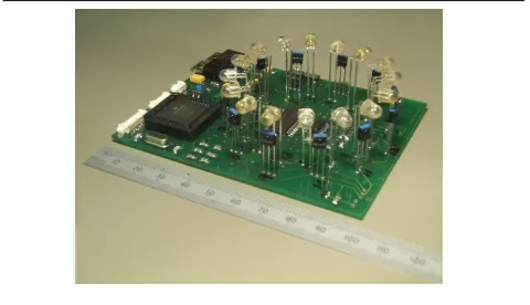
Figure 1 shows the implementation which has six-teen infrared emitters, twelve infrared receivers and addi-tional components including analog multiplexers and fil-ters, power circuitry and a microprocessor. The twelve pho-todetectors each cover 30° and the emitters 22°, therefore the angle measurement errors should be limited to±15° or ±11° respectively. Additionally, the wireless platform parti-cle computer1was used to organize the distributed control,
synchronization and exchange of measurements. It is impor-tant to note that these prototypes were designed to facilitate flexibility, in order to fully gauge the potential of infrared technology for fine-grained, surface-based positioning. The measurements are based on a series of short (each250µs) infrared pulses. The receivers include analogue filters and a 10bit 35kHz A/D Converter. A single pair-to pair measure-ment between two devices for any range up to 250cm and 360° coverage takes 600ms in the current implementation. The emission and reception of infrared pulses is organized in a one-to-many style. Many objects can measure their
in-1 http://particle.teco.edu
[image:3.595.316.556.122.260.2]coming signals while only one object emits pulses. This im-proves the scaling behavior when the number of objects in-creases.
Figure 1. Infrared device prototype
3.1. Location and orientation algorithms
As different devices emit infrared pulses and receiving devices measure and broadcast their results, angles of emis-sion/reception and inter-device ranges can be gathered for pairs of devices on the surface. Two methods for estimat-ing the relative locations and orientations of the devices are presented here.
Map tracing. A collection of the distance and angle readings reported can be used to construct a virtual map, whose nodes represent devices and whose segments repre-sent the distance and angle measurements between the de-vices. The map is then processed as follows:
1. Choose one device as the reference for the coordinate system.
2. Call a device with measurements towards another de-vice as connected to it.
3. Use trigonometry and the distance/angle readings of devices connected to the reference device and place those devices on the map. Mark the already placed de-vices as “visited”.
4. Choose a node which has not been visited, and cal-culate locations and orientations for any devices con-nected to it which has been placed already. Place the new node as well and mark it as “visited.”
5. Repeat the previous step until the location and orienta-tion for all devices in the map are calculated.
map tracing algorithm can be executed in real time, even us-ing a modest microcontroller such as the PIC employed in the prototype.
Non-linear regression. Alternatively, the angle and range measurements can be used to arrive at a solu-tion for the relative locasolu-tions and orientasolu-tions of the devices using a system of equations.
More specifically, taking devicei andj, with locations
(xi, yi) and (xj, yj), the euclidean distance dij between
them is:
dij =
q
(xi−xj)2+ (yi−yj)2. (1)
Also, the emission or reception angleψijat deviceiwith
respect to devicejcan be related toθi, the orientation of
de-viceireferenced to the arbitrary coordinate system being used by the relative positioning system
ψij=φij(xi, yi, xj, yj)−θi, (2)
whereφij is the angle of the vector drawn from deviceito
devicej, as shown in figure 2. As indicated in the equation,
φijis a function of the locations of the devicesiandj, and
can be calculated using trigonometry.
φij
Device i Angle of vector from
i to j
Device j
θi of device
Orientation
i
ψij
Angle of device with respect to device i
j
Relative positioning coordinate axes x
[image:4.595.59.291.367.524.2]y
Figure 2. Device angle relationships
Since the devices in the system report measurements of the distances dij and the angles ψij, a non-linear
regres-sion algorithm can be applied to arrive at estimates for the
devices’ relative locations and orientations on the surface. The regression process converges toward location and ori-entation estimates which minimise the sum of the squares of the residuals (i.e. the difference between devices’ measured distances and angles, and the distances and angles as calcu-lated using equations 1 and 2). The solution can be further refined by using Studentized residuals to identify distances and angles which are likely to have large errors, and re-peating the regression with those measurements discarded.
These techniques have previously been shown to work well in positioning systems [18].
4. Experiment and Discussion
This section presents a characterisation of the distance and angle measurements from the prototype devices, and the resulting location and orientation estimates. The practi-cal utility of such a system for mobile users is then evalu-ated. For the test setting, four prototype devices were placed in one hundred different configurations on a160×200cm surface indoors. For each configuration, the locations and orientations of the devices were arbitrarily chosen, with the aim of achieving an even distribution of locations and ori-entations over all the test configurations. Ambient light dur-ing the experiments came from overhead fluorescent lights and indirect sunlight.
4.1. Distance and angle accuracy
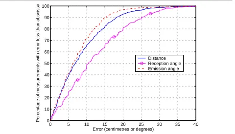
Figure 3 shows the error characteristic of the distance and angle measurements taken by the devices. Ninety per-cent of the distance measurements were within 18 cm. Al-though the chosen photodetectors each covers a fairly broad angular range, the beam intensity of the emitters used in the prototype is greatly attenuated when the emitter is turned by ten degrees or more. When a receiving device does not lie within the main lobe of sensitivity of any of the trans-mitting device’s emitters, measurements become less accu-rate. A simple software model to compensate for this was in place on the devices.
0 5 10 15 20 25 30 35 40 0
10 20 30 40 50 60 70 80 90 100
Error (centimetres or degrees)
Percentage of measurements with error less than abscissa
[image:4.595.320.560.468.605.2]Distance Reception angle Emission angle
Figure 3. Raw measurement accuracy
4.2. Location and orientation accuracy
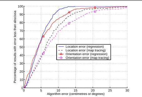
The measurement data for the experiments was fed into the map tracing and non-linear regression algorithms to produce relative location and orientation estimates. In or-der to compare the algorithms’ results with the manually-measured locations and orientations, a coordinate space transform was calculated for each result. The coordinate space transform consists of the 2D rotation and translation which minimise the mean squared distance error between corresponding devices. The accuracy of the resulting loca-tions and orientaloca-tions are shown in figure 4, and the nineti-eth and ninety-fifth percentile accuracies are given in ta-ble 1. Note that of the two algorithms, non-linear regres-sion achieves superior accuracy, but both algorithms have a location accuracy better than that of the raw distance mea-surements provided by the devices.
0 5 10 15 20 25 30
0 10 20 30 40 50 60 70 80 90 100
Algorithm error (centimetres or degrees)
Percentage of results with error less than abscissa
[image:5.595.60.287.290.445.2]Location error (regression) Location error (map tracing) Orientation error (regression) Orientation error (map tracing)
Figure 4. Algorithm accuracy distributions
4.3. Evaluation
Based on the findings with the prototype system, this section evaluates the use of infrared technology for fine-grained positioning of mobile users’ devices on surfaces.
Accuracy. The location and orientation accuracy of the system is largely suitable for the types of applications out-lined in section 2.1, such as configuration of device con-nections, automatic interface export, and location-sensitive data sharing between meeting attendees.
Update rate and scalability. In the current hard-ware prototypes, each device’s transmission sequence takes 600 ms. With some modifications this can easily be re-duced to less than 200 ms per device.
If line-of-sight between devices on the surface is mini-mal, then it may be necessary for all devices to transmit in order to uniquely solve for their locations and orientations.
Assuming a transmission duration of 200 ms and poor line-of-sight conditions on a surface with twenty objects, po-sitioning updates would be available approximately every four seconds. Although this would be awkward for users desiring fast, automatic connection and data sharing, in our experiences with surface-based systems, line-of-sight con-ditions are rarely so poor, and positioning updates are often feasible after only three or four devices report their mea-surements. Although only four infrared devices were con-structed, it has been experimentally verified that the wire-less protocol employed by the devices’ radio units will sup-port twenty or more devices in simultaneous operation.
Environmental factors. The reflectance of the surface on which the devices are placed affects the received in-frared light intensity. Although the devices perform simi-larly on typical desks and work surfaces, extremely shiny surfaces (such as glass) or absorbent surfaces (such as a black tablecloth) can cause additional ranging errors. Ad-ditionally, direct sunlight is crucial to the receivers used on the prototypes. section 2.1, mobile users rarely choose sur-faces which are in direct sunlight, since it makes device dis-plays difficult to read. Also, a set of informal experiments have shown that e.g. additional automatic calibration can compensate for ranging errors on unusually reflective or ab-sorbent surfaces.
Power Consumption. The prototypes have an aver-age power consumption of 300mW when actively generat-ing measurements. The biggest part of this relatively high power consumption is used up by the infrared circuitry. Ap-propriate redesigns can easily reduce this amout to less than 50mW by e.g. reducing the pulse length of the in-frared light pulses.
5. Conclusion
ac-Ninetieth percentile Ninety-fifth percentile Location Orientation Location Orientation
Raw values 18 cm 25° 22 cm 28°
Map tracing 14 cm 18° 17 cm 21°
[image:6.595.64.554.77.141.2]Non-linear regression 9 cm 12° 10 cm 14°
Table 1. Accuracy summary for measurements and location algorithms
curacy and update rate of the prototype devices is appro-priate for enhancing users’ surface-based applications with location-awareness. Using the regression algorithm, ninety-five percent of the positioning results returned by the sys-tem are accurate to 10 cm in location, and 14° in orienta-tion.
References
[1] James Scott, Frank Hoffmann, Glenford Mapp, Mike Addle-see, and Andy Hopper. Networked Surfaces: A new concept in mobile networking. ACM Mobile Networks and
Applica-tions, 7(5), October 2002.
[2] Jun Rekimoto and Masanori Saitoh. Augmented surfaces: A spatially continuous work space for hybrid computing en-vironments. In Proceedings of the Conference on Human
Factors in Computing Systems (CHI), pages 378–385,
Pitts-burgh, USA, May 1999.
[3] John Barton, Brad Johanson, Vikram Vijayaraghavan, Tony Hsieh, Tomoto Shimizu, and Armando Fox. The Meeting-Machine: Interactive workspace support for nomadic users. In Proceedings of the Workshop on Mobile Computing
Sys-tems and Applications, pages 2–12, Monterey, USA,
Octo-ber 2003.
[4] Brygg Ullmer, Hiroshi Ishii, and Dylan Glas. mediaBlocks: Physical containers, transports, and controls for online me-dia. In Proceedings of the Twenty-fifth International
Con-ference on Computer Graphics and Interactive Techniques (SIGGRAPH), pages 379–386, Orlando, USA, July 1998.
ACM.
[5] Mike Addlesee, Rupert Curwen, Steve Hodges, Joe New-man, Pete Steggles, Andy Ward, and Andy Hopper. Im-plementing a sentient computing system. IEEE Computer, 34(8):50–56, August 2001.
[6] Diego L´opez de Ipi˜na, Paulo Mendonc¸a, and Andy Hop-per. TRIP: A low-cost vision-based location system for ubiquitous computing. Personal and Ubiquitous
Comput-ing, 6(3):206–219, May 2002.
[7] Brygg Ullmer and Hiroshi Ishii. The MetaDESK: Models and prototypes for tangible user interfaces. In Proceedings
of the Symposium on User Interface Software and Technol-ogy (UIST), pages 223–232, Banff, Alberta, Canada,
Octo-ber 1997.
[8] John Underkoffler and Hiroshi Ishii. Urp: A luminous-tangible workbench for urban planning and design. In
Pro-ceedings of the Conference on Human Factors in Computing Systems (CHI), pages 386–393, Pittsburgh, USA, May 1999.
[9] Frank Hoffmann and James Scott. Location of mobile de-vices using Networked Surfaces. In Proceedings of
Ubi-Comp: Ubiquitous Computing, pages 281–298, G¨oteborg,
Sweden, September 2002.
[10] Albrecht Schmidt, Martin Strohbach, Kristof van Laerhoven, Adrian Friday, and Hans-Werner Gellersen. Context acqui-sition based on load sensing. In Proceedings of UbiComp:
Ubiquitous Computing, pages 333–350, G¨oteborg, Sweden,
September 2002.
[11] Ken Camarata, Ellen Yi-Luen Do, Brian D. Johnson, and Mark D. Gross. Navigational blocks: Navigating informa-tion space with tangible media. In Proceedings of the
In-ternational Conference on Intelligent User Interfaces (IUI),
pages 31–38, San Francisco, USA, January 2002.
[12] James Patten, Hiroshi Ishii, Jim Hines, and Gian Pangaro. Sensetable: a wireless object tracking platform for tangible user interfaces. In Proceedings of the Conference on Human
Factors in Computing Systems (CHI), pages 253–260,
Seat-tle, USA, April 2001.
[13] Roy Want, Andy Hopper, Veronica Falcao, and Jon Gibbons. The Active Badge location system. ACM Transactions on
In-formation Systems, 10(1):91–102, January 1992.
[14] Roy Want, Bill Schilit, Norman Adams, Rich Gold, Karin Petersen, David Goldberg, John Ellis, and Mark Weiser. An overview of the ParcTab ubiquitous computing experi-ment. IEEE Personal Communications, 2(6):28–33, Decem-ber 1995.
[15] Dana Kirsch and Thad Starner. The Locust Swarm: An environmentally-powered, networkless location and messag-ing system. In Proceedmessag-ings of the First International
Sympo-sium on Wearable Computers, Boston, USA, October 1997.
[16] Drexel Hallaway, Tobias H¨ollerer, and Steven Feiner. Coarse, inexpensive, infrared tracking for wearable comput-ing. In Proceedings of the Seventh IEEE International
Sym-posium on Wearable Computers (ISWC), pages 69–78, White
Plains, NY, USA, October 2003.
[17] Greg Welch, Gary Bishop, Leandra Vicci, Stephen Brum-back, Kurtis Keller, and D’nardo Colucci. The HiBall tracker: High-performance wide-area tracking for virtual and augmented environments. In Proceedings of the ACM
Sym-posium on Virtual Reality Software and Technology,
Univer-sity College London, United Kingdom, December 1999. [18] Andy Ward, Alan Jones, and Andy Hopper. A new location
technique for the active office. IEEE Personal