N A N O E X P R E S S
Open Access
Morphological Evolution of Pit-Patterned
Si(001) Substrates Driven by Surface-Energy
Reduction
Marco Salvalaglio
1,2*, Rainer Backofen
1, Axel Voigt
1,3and Francesco Montalenti
4Abstract
Lateral ordering of heteroepitaxial islands can be conveniently achieved by suitable pit-patterning of the substrate prior to deposition. Controlling shape, orientation, and size of the pits is not trivial as, being metastable, they can significantly evolve during deposition/annealing. In this paper, we exploit a continuum model to explore the typical metastable pit morphologies that can be expected on Si(001), depending on the initial depth/shape. Evolution is predicted using a surface-diffusion model, formulated in a phase-field framework, and tackling surface-energy anisotropy. Results are shown to nicely reproduce typical metastable shapes reported in the literature. Moreover, long time scale evolutions of pit profiles with different depths are found to follow a similar kinetic pathway. The model is also exploited to treat the case of heteroepitaxial growth involving two materials characterized by different facets in their equilibrium Wulff’s shape. This can lead to significant changes in morphologies, such as a rotation of the pit during deposition as evidenced in Ge/Si experiments.
Keywords: Epitaxy, Silicon, Surface diffusion, Phase field, Surface energy
Background
Lattice-mismatched heteroepitaxy of several semiconduc-tors (such as Ge/Si or InGaAs/GaAs) can lead to the formation of 3D islands, following the Stranski-Krastanow (SK) growth mode. While the possibility to obtain such dots by pure self-assembly [1, 2] is particularly appealing and generated widespread interest, it was soon realized that random nucleation could severely hinder applica-tions, along with dispersion in size and shape.
Decades of research led to the development of a wide variety of methods to drive heteroepitaxial growth towards the formation of ordered structures [3–7]. Among them, the usage of pit-patterned substrates has been demonstrated to be one of the most versatile meth-ods in order to achieve both high ordering and size control of heteroepitaxial islands [8–15].
*Correspondence: [email protected]
1Institute of Scientific Computing, Technische Universität Dresden, 01062
Dresden, Germany
2IHP, Im Technologiepark 25, 15236 Frankfurt (Oder), Germany
Full list of author information is available at the end of the article
Pit-patterned substrates are usually fabricated by means of methods such as nanoimprint lithography [16–18], e-beam lithography [13, 14] combined with reactive ion etching (RIE) [19, 20] or wet chemical etching [21, 22], and nanoindentation [23, 24], i.e., by top-down approaches. With these methods, ordered patterns of pits are designed with high precision and, under proper growth conditions [14, 25], lead to almost perfect lateral ordering.
As the actual shape of pits does influence the energy of the system and, more in general, island nucleation [26, 27], it is crucial to control their morphology. This is not trivial: after all, pits are just holes drilled into the substrate. Thus, at sufficiently high temperatures, capil-larity [28] is expected to produce a morphological evolu-tion, eventually leading to full healing. Actually, annealing processes or further deposition of the substrate mate-rial following the initial pit formation are often used in order to achieve reproducible, long-lived metastable shapes [8, 26]. Notice that even once a pit is stabilized in shape, further evolution can be driven during actual heteroepitaxy [29, 30].
In this work, we aim at describing the evolution of pit-patterned substrates driven by surface energy reduction via surface diffusion. We adopt a suitable phase-field approach [31], allowing for the simulation of length and time scales compatible with the experimental ones [32]. The model has been already adopted to account for diffusion-limited kinetics during the morphological evo-lution in heteroepitaxial systems [33–36]. Moreover, it has been shown to properly describe the evolution towards equilibrium including realistic anisotropic surface energies [37–39].
Without the loss of generality, we shall focus on the relevant cases of pit-patterned Si(001) surfaces, widely investigated in the literature [8, 10, 14, 30, 40, 41].
The work is organized as follows. In the “Phase-Field Model” section, we briefly illustrate the phase-field model used to describe the evolution by surface diffusion includ-ing anisotropic surface energy. Moreover, we describe how the actual Si Wulff shape is accounted for in the considered approach. In the “Smoothing of Si(001) Pits” section, the expected smoothing of Si(001) pits, driven by the surface-energy reduction, is discussed by consid-ering different initial configurations, outlining the kinetic pathway towards the equilibrium. In the “Mimicking the Shape Change due to Ge Overgrowth” section, an appli-cation of the method to a specific case of heteroepitax-ial growth that corresponds to the surface-energy-driven shape change when depositing a thin layer of Ge on Si pit is considered. Conclusions and remarks are summarized in the “Conclusions” section.
Methods
Phase-Field Model
The phase field model considers a continuous order parameterϕ, varying betweenϕ = 1 (solid) and ϕ = 0 (vacuum) [31, 32]. The approach is based on an energy functional [37],
F=
γ (nˆ)
2|∇ϕ| 2+ 1
B(ϕ)
dr+
+
β 2
−∇2ϕ+1 B(ϕ)
2 dr,
(1)
with ∈ R3 the domain of definition of ϕ(r) and
r = (x,y,z). The first term corresponds to the inter-face energy between phases within the diffuse-interinter-face domain defined by ϕ, i.e., to the surface energy of the solid phase.γ (nˆ)is the surface energy density, withnˆthe outward-pointing surface normal, and the thickness of the interface between phases.B(ϕ) = 18ϕ2(1−ϕ)2is a double-well potential with a minima inϕ = 0 andϕ = 1 as in Ref. [31]. The second term in Eq. (1) is the Willmore regularization that is required in the strong anisotropy
regime to avoid the formation of sharp corners [37, 38, 42]. βis a parameter corresponding to the corner rounding.
The evolution for ϕ reproduces the diffusion-limited kinetics of surfaces and is given by the degenerate Cahn-Hilliard model, i.e.,
∂ϕ
∂t =D∇[M(ϕ)∇μ] , (2)
whereμ = δF/δϕis the chemical potential,Dis the dif-fusion coefficient, andM(ϕ) = (36/)ϕ2(1−ϕ)2is the mobility function restricted to the surface. The equation forμreads
g(ϕ)μ=δF/δϕ= −∇ ·γ (nˆ)∇ϕ+1
γ (nˆ)B(ϕ)+ −∇ ·|∇ϕ|2∇∇
ϕγ (nˆ)+
+β
−∇2κ+ 1 2B(ϕ)κ
, (3) withκ = −∇2ϕ+(1/)B(ϕ)andg(ϕ)= 30ϕ2(1−ϕ)2 [33, 37, 38]. The latter is a stabilizing function which ensures second-order convergence in the interface thick-ness, without affecting the description of material trans-port via surface diffusion [43, 44]. The profile in the direction perpendicular to the interface at equilibrium is well described by
ϕ(r)= 1
2
1−tanh
3d(r)
, (4)
where d(r) is the signed distance to the center of the interface between phases. This equation is adopted to set the initial condition for ϕ as specified in the fol-lowing. We refer to the surface of the solid phase as theϕ ∼ 0.5 isosurface. All the geometrical properties of the considered surface can be derived fromϕ, such as the outward-pointing surface normalnˆ = −∇ϕ/|∇ϕ|. Anisotropic Surface Energy
In order to describe anisotropic surface energies, we con-sidered the definition of the surface energy density,γ (nˆ), as introduced in [38, 39]:
γ (nˆ)=γ0 1− N
i
αi
ˆ
n· ˆmi wiˆ
n· ˆmi
. (5)
where the preferential orientationsmˆi, i.e., the directions
along which the surface-energy density has a minimum, can be arbitrarily set along with their relative depths, αi, with respect to γ0. The parameters wi control the
extension of the regions where γ (nˆ) < γ0 around mi
directions, i.e., they are namely the widths of the minima (see also Ref. [38]).
to 001, 113, 110, and 111 [45]. αi coefficients,
determining the depth of minima, are obtained by [39]
αi=1−
γ
i
γ001
1−α001, (6)
whereα001 = 0.15 is set as reference and the variousγi
correspond to the surface energy values of the aforemen-tioned orientations as reported in Ref. [45]. Without the loss of generality, we setγ0= 1. Indeed, the ratios of the minima and the strength of the anisotropy can be con-trolled by theαi values from Eq. (6) andα001, whileγ0 plays the role of a prefactor in Eq. (2), thus affecting only the absolute time scale of the evolution.
[image:3.595.305.540.462.653.2]The width of the energy minima in Eq. (5) are set to wi = 50 for all the minima directions, except for w113 = 100 [39]. According to this definition of the parameters, sharp corners are predicted in the Wulff shape, i.e., the surface-energy anisotropy is “strong” [38, 42, 46]. Therefore, the Willmore regularization is strictly necessary to perform the simulations. Theβvalue sets the extension of the rounded region at the corners, which are known to have a radius proportional to√β[37]. In order to perform simulations, the length scale set by the rounding at the corner byβ has to be larger than the resolution of the spatial discretization of the numerical method. However, it is worth mentioning that small facets possibly present in the Wulff shape with an extension in the order of√β may result hidden when using too large βvalues as well as small scale faceting involving preferen-tial orientations actually present in the Wulff shape. In this work, we setβ=0.005. According to the size of the simu-lation domain, specified in the following, this value allows us to adopt feasible spatial discretization. Moreover, all the preferential orientations entering Eqs. (5) and (6) are reproduced. On the other hand, possible faceting involv-ing smaller scales than∼0.07 cannot be reproduced due to the extension of the corner rounding.
Initial Morphology and Simulation Setup
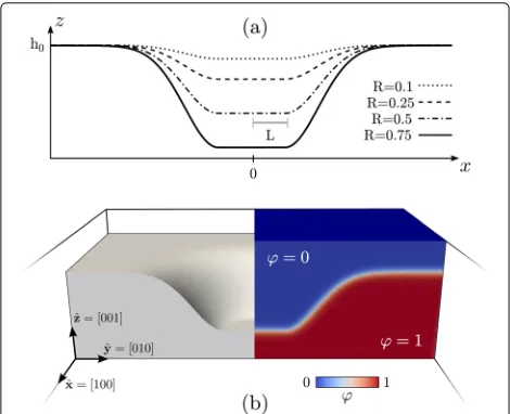
In order to investigate any morphological evolution by the phase-field model defined in this section, a proper initial condition forϕhas to be set. We consider here a smooth pit geometry carved in a (001) planar surface, with a ref-erence frame set toxˆ =[100],yˆ=[010], andzˆ=[001]. In particular, we consider a circular (001) surface with radius Lat a heighth0−H, smoothly connected to the surround-ing (001) planar surface at heighth0. Such a geometry is set as initial condition forϕby exploiting Eq. (4) withd(r)
the signed distance from the surface(x,y)defined by
(x,y)= ⎧ ⎪ ⎨ ⎪ ⎩
h0−H r≤L
h0−Hexp
−1
2
|s− ¯s|2
σ2
r>L (7)
withr=x2+y2and
s=(x,y), s¯= R
r(x,y). (8)
R = H/4Lis defined as an aspect-ratio parameter, while σ is a parameter controlling the extension of the contin-uous connection between the bottom of the pit and the flat region surrounding it. This parameter is set here to σ = L/2.
In Fig. 1, the initial condition adopted forϕis illustrated. Figure 1a shows(x, 0)profiles with different values ofR. Figure 1b shows the definition ofϕby means of Eq. (4) in a 3D parallelepiped domain. In particular, this panel shows a cross-section passing through the center of the whole domain. The left part shows the region corresponding to the solid phase, i.e., the region whereϕ > 0.5, revealing the surface that corresponds to the initial pit morphology. The right part illustrates the values ofϕin the entire 3D domain, i.e., in the bulk phases and within the continuous transition between them.
Numerical simulations are performed to integrate Eqs. (2) and (3). They are carried out by using the finite element method (FEM) toolbox AMDiS [47, 48], with a semi-implicit integration scheme and mesh refinement at the interface [33, 38, 49]. Periodic boundary conditions are set alongxˆ andyˆdirections. No-flux (Neumann) bound-ary conditions are set at the top and the bottom of the simulation domain along thezˆdirection. The time scale of the evolution is scaled by a factor 1/D, which corre-sponds to setD=1. In the following, we refer to the time
of simulations in arbitrary units. The size of the pit is arbi-trarily set toL = 1, while the interface thickness is set to=0.2.
Results and Discussion
Smoothing of Si(001) Pits
In this section, we illustrate the results concerning the morphological changes during the evolution of pit-patterned Si(001) substrates. The model described above allows for the description of the specific case of silicon by means of the definition of the anisotropic surface energy as in the “Anisotropic Surface Energy” section. We expect the following results to be valid from a qualitative point of view for any size, provided that the system is large enough to adopt a continuum approach ( 10 nm) [32] and the shape can be parametrized by the aspect ratioRsimilar to Fig. 1a. The real length scale can be considered by setting the Lparameter to the corresponding one in real units, Lr. The real time scale can then be described by account-ing for real values ofDandγ0and multiplying by theLr length, i.e., by scaling byLr/LwithLunitary as specified above.
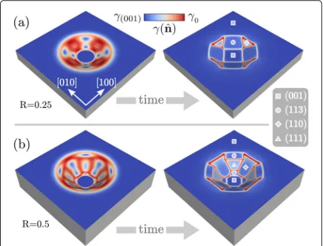
Let us first focus on the first stages of the evolution. The initial condition set by Eq. (7) consists of a profile which does not exhibit any preferential orientation of the sur-face. When considering the evolution by surface diffusion driven by the reduction of an anisotropic surface energy, a faceting of the initial profile is expected. This is illus-trated in Fig. 2 where the faceting of two profiles with R = 0.25 in Fig. 2a andR = 0.5 in Fig. 2b are reported. A color scale illustrates the values γ (nˆ) at the surface.
Fig. 2Faceting of the initial profile as defined in the “Initial Morphology and Simulation Setup” section according to surface diffusion and γ (nˆ)reproducing the surface energy of Si. Two different initial morphologies are considered:aR = 0.25 andbR = 0.5. On the faceted morphologies, symbols are adopted to identify the families of facets. The color scale shows the values ofγ (nˆ)at the surface
This allows to identify the facets as the regions with an almost uniform surface-energy density corresponding to the minima of Eq. (5), bounded by localized regions with high values ofγ (nˆ). According to the initial aspect ratio of the pit, different facets form. For the smaller R, the (001) facet at the bottom is maintained assuming a squared shape. The edges of the pit result bounded by four{113} facets connected by small, triangular-shaped{110}facets. According to the larger aspect ratio, a larger faceted sur-face is present when consideringR=0.5, allowing for the appearance of preferential orientations with higher slope with respect to the (001) surface. In particular, the ini-tial shape allows for the presence of{111}facets forming between two{113}facets close to the bottom and to the flat region. In between, wide{110}facets form.
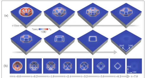
The results reported in Fig. 2 show the possibility to pre-dict faceted pit morphology according to the aspect ratio or, in general, according to the initial morphology. We now investigate also the long time scale dynamics inspecting the morphological evolution up to equilibrium [38]. This is illustrated in Fig. 3 where we focus on the deepest pit considered so far, i.e., withR = 0.5, and the main mor-phological changes are shown. In particular, perspective and top views of the different morphologies obtained dur-ing the evolution are reported in Fig. 3a, b, respectively. In the first stage of this simulation, we observe the disap-pearance of the steepest{111}facets and the enlargement of neighbouring{113}facets. Then, the latters merge and the shrinkage of{110} facets begins. These are found to disappear at later stages after assuming a triangular shape, giving a square outline to the pit from a top view. Also,
{113} facets eventually vanish and a global flattening is achieved. The real time scale obtained in this simulation can be estimated with data from the literature. In particu-lar, we can considerDdetermined by Arrhenius law with prefactor and activation energy from Ref. [50], where also thermal fluctuations are accounted for. γ0 is set to have γ (nˆ) ∼ 8.7 eV/nm2whennˆ = (001)[51] from Eq. (5), that is,γ0=10.2 eV/nm2. The other material-dependent coefficients of surface diffusion [28], i.e., atomic volume and density at the surface, are set to reproduce the case of Si. According to these values, the expected duration of the entire process at high temperature T∼ 1100 − 1200 ◦C for Lr of tens of nanometers is in the order of hours.
[image:4.595.56.292.484.663.2]Fig. 3Evolution towards the equilibrium for a Si pit having an initial morphology as in Fig. 2b.aPerspective view showing the main morphological changes.bTop view of the morphologies in panela. The time reported in panelbis expressed in arbitrary units. The color scale shows the values of γ (nˆ)at the surface
facets but with different relative sizes. This is in agree-ment with the fact that the morphologies obtained during the evolution correspond to out-of-equilibrium configu-rations and define a pathway towards the global energy minimum. Then, despite the expected facets and their energetics are known, the specific morphology at a certain point of the evolution can be described only by accounting for the dynamics and not just by considering global energy minimization [38].
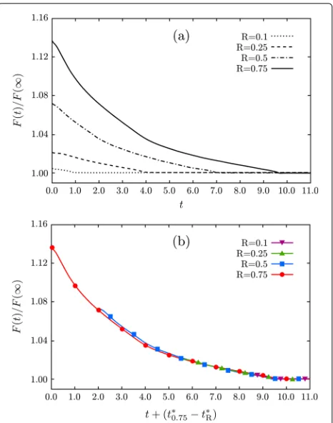
The second important point shown by the results reported in Fig. 3 is about the intermediate stages. When the shape during the evolution approaches a geometry with a depth similar to the initial profile obtained with R = 0.25, i.e., at t ∼ 3.2, the morphology induced by the energy minimization resembles very closely what is reported in Fig. 2b, even when starting from an initial configuration with a significant difference in the depth (double in this case). This suggests the existence of a com-mon kinetic pathway toward the final flattening, which is reached after the first fast faceting of the initial mor-phology. This argument is actually confirmed and further illustrated in the plots of Fig. 4. Here, the monotonous energy decay during the evolution after the initial faceting is reported when considering pits with R equal to 0.1, 0.25, 0.5, and 0.75 as in Fig. 1a. In Fig. 4a, the time scale expressed in arbitrary units is considered. In Fig. 4b, the
same energy changes are reported with a proper shift of the time scale, highlighting the similar energy decay when approaching similar aspect ratios of the structure. t∗R is defined as the time at which the planar surface is obtained, i.e., the time at which the global energy mini-mum is reached, that is different for each simulation as shown in Fig. 4a. As shown in this plot, the energy decays almost overlap for R ≤ 0.5. A very small difference is observed only when consideringR= 0.75, whose energy decay results are still very close to the other curves and differences basically vanish for t 5.0. It is worth mentioning that for large deviations from the initial con-figuration, namely, with R 1, such geometries may evolve differently with different effects on time scales and morphologies [52, 53]. Moreover, topological changes are known to occur in extreme cases, e.g., with very deep trenches, preventing the possibility to reach the global equilibrium with a flat (001) surface [34, 39, 54].
[image:5.595.52.542.85.351.2]Fig. 4Energy decreasing during the evolution of pit geometries.
aF(t) normalized by the energy of the flat (001) surface obtained as final stage of the evolution. Energy decays obtained from the simulations having differentRfor the initial profile, namely, fromR = 0.1 to
R= 0.75, are shown. Time is expressed in arbitrary units.bCurves as in panelashifted in order to matchtR∗, i.e., the time at which the global flattening of the pit is achieved depending onR
when considering pit-patterned Si(001) substrates with an aspect ratio of 0.05 < R < 0.1 as in Ref. [10, 30]. Also, the relative extension of the facets in the aforemen-tioned stage of the simulation of Fig. 3 is very similar to what was reported in these experimental works. This agreement between simulations and experiments further assesses the theoretical description of surface diffusion adopted here. However, we focused on the general fea-tures of the process and a more detailed comparison to specific experiments is out of the purpose of the present work.
Mimicking the Shape Change due to Ge Overgrowth As mentioned in the introduction, one of the main appli-cations of pit-patterned Si templates is the control of the growth of self-assembled islands [55]. This holds true in particular when considering the positioning of Ge or Si1−cGec islands on Si(001) substrates [6]. With
the methodology adopted in the previous section, we can inspect the morphological changes related to the peculiar features of the surface energy. Therefore, by starting from
a proper initial configuration resembling the real mor-phology of a Si pit and accounting for the differences in the surface-energy density expected when depositing another material, we can predict what is the corresponding contri-bution to morphological changes.
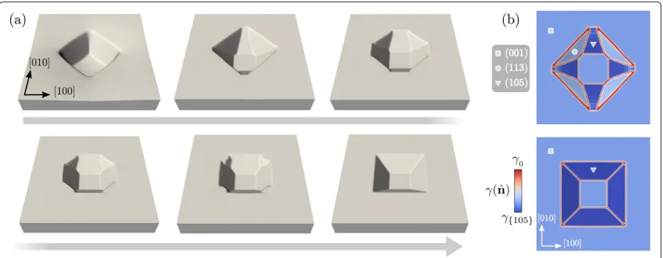
The case study consists here in the overgrowth of Ge over a Si(001) pit-patterned substrate with an aspect ratio close to 0.1. The profile of Fig. 3 att = 5.0 is considered as an initial morphology. Then, a surface energy includ-ing also a minima along the105directions is set. This definition ofγ (nˆ)mimics the presence of the small-slope most favorite orientation in Ge/Si(001) systems [56–58]. The high stability of{105}facets is due to the interplay between surface reconstruction and strain effects related to the lattice mismatch between the epilayer and the sub-strate [59–61]. The surface-energy density value which has to be used in Eq. (6) is taken from Ref. [58] in the limit of a thick Ge layer. Notice that other facets that have a surface energy closer to the (001), such as{1 1 10}, are neglected here. As the angles between the105and the [001] directions are very small,wiparameters larger than
the ones adopted before are required to properly describe the energy minima of Eq. (5) [38]. In particular, we set w{105}=w{001}=500.
[image:6.595.58.291.85.381.2]Fig. 5Evolution of the profile in Fig. 3 att=5.0, with a definition of the surface energy including105orientations.aSurface profiles at representative stages of the evolution towards the formation of a pit bounded by{105}facets only.z-axis is magnified by a factor 5.bTop view showing theγ (nˆ)values at the surface. The second and the last stages of panelaare reported in the top and bottom part, respectively. Symbols as in Fig. 2 are adopted to identify different families of facets
initial configuration of Fig. 4 with just a smaller slope with respect to the (001) plane.
Conclusions
In this work, we have used a continuum model based on surface-diffusion to investigate the temporal evolution of pits excavated in a Si(001) substrate. By suitably tackling (strong) surface-energy anisotropy, with a parametriza-tion based on the well-known Si Wulff ’s shape, we have predicted typical metastable configurations in agreement with experiments, including the case where deposition of a different material introduces new stable facets. The entire evolution towards the global flattening of the pit has been illustrated, and it is found to follow the same kinetic pathway also when considering pits with different initial depths. We believe that the model can be predic-tive also for initial configurations strongly deviating from the ones which we have analyzed as examples. As a con-sequence, the present approach can be useful in designing experiments based on still-unexplored pit shapes. Fur-thermore, the model is general and can be easily adapted to different substrates upon re-parametrizing the surface energy.
Acknowledgements
MS acknowledges the support of the Postdoctoral Research Fellowship awarded by the Alexander von Humboldt Foundation. FM acknowledges the financial support from Regione Lombardia, under the TEINVEIN project, called “Accordi per la Ricerca e l’Innovazione,” co-funded by POR FESR 2014-2020 (project ID: 242092). The computational resources were provided by ZIH at TU Dresden and by the Jülich Supercomputing Center within the Project No. HDR06.
Authors’ Contributions
FM and MS conceived the investigation. MS and RB under the supervision of AV developed and implemented the phase-field model. MS performed the
simulations. MS and FM wrote the manuscript with inputs from all the authors. All the authors read and approved the final manuscript.
Competing Interests
The authors declare that they have no competing interests.
Publisher’s Note
Springer Nature remains neutral with regard to jurisdictional claims in published maps and institutional affiliations.
Author details
1Institute of Scientific Computing, Technische Universität Dresden, 01062
Dresden, Germany.2IHP, Im Technologiepark 25, 15236 Frankfurt (Oder),
Germany.3Dresden Center for Computational Materials Science (DCMS),
01062 Dresden, Germany.4L-NESS and Department of Materials Science,
Università di Milano-Bicocca, via R. Cozzi 55, I-20126 Milano, Italy.
Received: 4 July 2017 Accepted: 17 September 2017
References
1. Mo YW, Savage DE, Swartzentruber BS, Lagally MG (1990) Kinetic pathway in Stranski-Krastanov growth of Ge on Si(001). Phys Rev Lett 65:1020 2. Leonard D, Krishnamurthy M, Reaves CM, Denbaars SP, Petroff PM (1993)
Direct formation of quantum sized dots from uniform coherent islands of InGaAs on GaAs surfaces. Appl Phys Lett 63:3203
3. Teichert C (2002) Self-organization of nanostructures in semiconductor heteroepitaxy. Phys Rep 365:335
4. Brunner K (2002) Si/Ge nanostructures. Rep Prog Phys 65:27
5. Lourdudoss S (2012) Heteroepitaxy and selective area heteroepitaxy for silicon photonics. Curr Opinion Solid State Mater Sci 16:91
6. Aqua JN, Berbezier I, Favre L, Frisch T, Ronda A (2013) Growth and self-organization of SiGe nanostructures. Phys Rep 522:59
7. Bergamaschini R, Isa F, Falub CV, Niedermann P, Müller E, Isella G, et al (2013) Self-aligned Ge and SiGe three-dimensional epitaxy on dense Si pillar arrays. Surf Sci Rep 68:390
8. Zhong Z, Halilovic A, Fromherz T, Schäffler F, Bauer G (2003) Two-dimensional periodic positioning of self-assembled Ge islands on prepatterned Si (001) substrates. Appl Phys Lett 82:4779 9. Kiravittaya S, Heidemeyer H, Schmidt OG (2004) Growth of
[image:7.595.58.541.86.274.2]10. Zhang JJ, Stoffel M, Rastelli A, Schmidt OG, Jovanovi´c V, Nanver LK, et al (2007) SiGe growth on patterned Si(001) substrates: surface evolution and evidence of modified island coarsening. Appl Phys Lett 91:173115 11. Katsaros G, Tersoff J, Stoffel M, Rastelli A, Acosta-Diaz P, Kar GS, et al (2008)
Positioning of strained islands by interaction with surface nanogrooves. Phys Rev Lett 101:096103
12. Kiravittaya S, Rastelli A, Schmidt OG (2009) Advanced quantum dot configurations. Rep Prog Phys 72:046502
13. Vescan L, Stoica T, Holländer B, Nassiopoulou A, Olzierski A, Raptis I, Sutter E (2003) Self-assembling of Ge on finite Si(001) areas comparable with the island size. Appl Phys Lett 82:3517
14. Grydlik M, Langer G, Fromherz T, Schäffler F, Brehm M (2013) Recipes for the fabrication of strictly ordered Ge islands on pit-patterned Si(001) substrates. Nanotechnology 24:105601
15. Grydlik M, Brehm M, Hackl F, Schäffler F, Bauer G, Fromherz T (2013) Unrolling the evolution kinetics of ordered SiGe islands via Ge surface diffusion. Phys Rev B 88:115311
16. Chou SY, Krauss PR, Renstrom PJ (1996) Imprint lithography with 25-nanometer resolution. Science 272:85
17. Austin MD, Ge H, Wu W, Li M, Yu Z, Wasserman D, Lyon SA, Chou SY (2004) Fabrication of 5 nm linewidth and 14 nm pitch features by nanoimprint lithography. Appl Phys Lett 84:5299
18. Lausecker E, Brehm M, Grydlik M, Hackl F, Bergmair I, Mühlberger M, Fromherz T, Schäffler F, Bauer G (2011) UV nanoimprint lithography for the realization of large-area ordered SiGe/Si(001) island arrays. Appl Phys Lett 98:143101
19. Jansen H, Gardeniers H, de Boer M, Elwenspoek M, Fluitman J (1996) A survey on the reactive ion etching of silicon in microtechnology. J Micromech Microeng 6:14
20. Karouta F (2014) A practical approach to reactive ion etching. J Phys D: Appl Phys 47:233501
21. Seidel H, Csepregi L, Heuberger A, Baumgartel H (1990) Anisotropic etching of crystalline silicon in alkaline solutions. J Electrochem Soc 137:3612
22. Goslvez MA, Nieminen RM (2003) Surface morphology during anisotropic wet chemical etching of crystalline silicon. New J Phys 5:100
23. Gong J, Lipomi DJ, Deng J, Nie Z, Chen X, Randall NX, Nair R, Whitesides GM (2010) Micro- and nanopatterning of inorganic and polymeric substrates by indentation lithography. Nano Lett 1:2702
24. Alkhatib A, Nayfeh A (2013) A complete physical germanium-on-silicon quantum dot self-assembly process. Sci Rep 3:2099
25. Bergamaschini R, Montalenti F, Miglio L (2010) Optimal growth conditions for selective Ge islands positioning on pit-patterned Si(001). Nanoscale Res Lett 5:1873
26. Vastola G, Grydlik M, Brehm M, Fromherz T, Bauer G, Boioli F, et al (2011) How pit facet inclination drives heteroepitaxial island positioning on patterned substrates. Phys Rev B 84:155415
27. Mayer CJ, Helfrich MF, Schaadt DM (2013) Influence of hole shape/size on the growth of site-selective quantum dots. Nanoscale Res Lett 8:504 28. Mullins WW (1957) Theory of thermal grooving. J Appl Phys 28:333 29. Bergamaschini R, Tersoff J, Tu Y, Zhang JJ, Bauer G, Montalenti F (2012)
Anomalous smoothing preceding island formation during growth on patterned substrates. Phys Rev Lett 109:156101
30. Chen HM, Kuan CH, Suen YW, Luo GL, Lai YP, Wang FM, et al (2012) Thermally induced morphology evolution of pit-patterned Si substrate and its effect on nucleation properties of Ge dots. Nanotechnology 23:015303
31. Li B, Lowengrub J, Ratz A, Voigt A (2009) Review article: Geometric evolution laws for thin crystalline films: modeling and numerics. Commun Comput Phys 6:433
32. Bergamaschini R, Salvalaglio M, Backofen R, Voigt A, Montalenti F (2016) Continuum modelling of semiconductor heteroepitaxy: an applied perspective. Adv Phys X 1:331
33. Rätz A, Ribalta A, Voigt A (2006) Surface evolution of elastically stressed films under deposition by a diffuse interface model. J Comput Phys 214:187
34. Salvalaglio M, Bergamaschini R, Isa F, Scaccabarozzi A, Isella G, Backofen R, et al (2015) Engineered coalescence by annealing 3D Ge microstructures into high-quality suspended layers on Si. ACS Appl Mat Interfaces 7:19219 35. Albani M, Bergamaschini R, Montalenti F (2016) Dynamics of pit filling in
heteroepitaxy via phase-field simulations. Phys Rev B 94:075303
36. Salvalaglio M, Backofen R, Voigt A (2016) Thin-film growth dynamics with shadowing effects by a phase-field approach. Phys Rev B 94:235432 37. Torabi S, Lowengrub J, Voigt A, Wise S (2009) A new phase-field model for
strongly anisotropic systems. Proc R Soc London Ser A 465:1337 38. Salvalaglio M, Backofen R, Bergamaschini R, Montalenti F, Voigt A (2015)
Faceting of equilibrium and metastable nanostructures: a phase-field model of surface diffusion tackling realistic shapes. Cryst Growth Des 15:2787
39. Salvalaglio M, Bergamaschini R, Backofen R, Voigt A, Montalenti F, Miglio L (2017) Phase-field simulations of faceted Ge/Si-crystal arrays, merging into a suspended film. Appl Surf Sci 391:33
40. Di Gaspare L, Palange E, Capellini G, Evangelisti F (2000) Strain relaxation by pit formation in epitaxial SiGe alloy films grown on Si(001). J Appl Phys 88:120
41. Chen G, Lichtenberger H, Bauer G, Jantsch W, Schäffler F (2006) Initial stage of the two-dimensional to three-dimensional transition of a strained SiGe layer on a pit-patterned Si(001) template. Phys Rev B 74:035302 42. Spencer BJ (2004) Asymptotic solutions for the equilibrium crystal shape
with small corner energy regularization. Phys Rev E 69:011603 43. Gugenberger C, Spatschek R, Kassner K (2008) Comparison of phase-field
models for surface diffusion. Phys Rev E 78:016703
44. Voigt A (2016) Comment on “Degenerate mobilities in phase field models are insufficient to capture surface diffusion”. Appl Phys Lett 108:036101 45. Bermond JM, Métois JJ, Egéa X, Floret F (1995) The equilibrium shape of
silicon. Surf Sci 330:48
46. Eggleston JJ, McFadden GB, Voorhees PW (2001) A phase-field model for highly anisotropic interfacial energy. Physica D 150:91
47. Vey S, Voigt A (2007) AMDiS: adaptive multidimensional simulations. Comput Visual Sci 10:57
48. Witkowski T, Ling S, Praetorius S, Voigt A (2015) Software concepts and numerical algorithms for a scalable adaptive parallel finite element method. Adv Comput Math 41:1145
49. Chen F, Shen J (2013) Efficient energy stable schemes with spectral discretization in space for anisotropic Cahn-Hilliard systems. Commun Comput Phys 13:1189
50. Acosta-Alba PE, Kononchuk O, Gourdel C, Claverie A (2014) Surface self-diffusion of silicon during high temperature annealing. J Appl Phys 13:134903
51. Lu G-H, Cuma M, Liu F (2005) First-principles study of strain stabilization of Ge(105) facet on Si(001). Phys Rev B 72:125415
52. Castez MF (2010) Surface-diffusion-driven decay of patterns: beyond the small slopes approximation. J Phys Condens Matter 22:345007 53. Castez MF, Salvarezza RC, Nakamura J, Sudoh K (2010) A theoretical
framework to obtain interface’s shapes during the high-temperature annealing of high-aspect-ratio gratings. Appl Phys Lett 97:123104 54. Bergamaschini R, Salvalaglio M, Scaccabarozzi A, Isa F, Falub CV, Isella G,
et al (2016) Temperature-controlled coalescence during the growth of Ge crystals on deeply patterned Si substrates. J Cryst Growth 440:86 55. Medeiros-Ribeiro G (1998) Shape transition of germanium nanocrystals
on a Silicon (001) surface from pyramids to domes. Science 279:353 56. Goldfarb I, Hayden PT, Owen JHG, Briggs GAD (1997) Nucleation of “Hut”
pits and clusters during gas-source molecular-beam epitaxy of Ge/Si(001) in in situ scanning tunnelng microscopy. Phys Rev Lett 78:3959 57. Robinson JT, Rastelli A, Schmidt O, Dubon OD (2009) Global faceting
behavior of strained Ge islands on Si. Nanotechnology 20:085708 58. Montalenti F, Scopece D, Miglio L (2013) One-dimensional Ge
nanostructures on Si(001) and Si(1 1 10): dominant role of surface energy. C R Phys 14:542
59. Raiteri P, Migas DB, Miglio L, Rastelli A, von Känel H (2002) Critical role of the surface reconstruction in the thermodynamic stability of {105} Ge pyramids on Si(001). Phys Rev Lett 88:256103
60. Migas DB, Cereda S, Montalenti F, Miglio L (2004) Electronic and elastic contributions in the enhanced stability of Ge(105) under compressive strain. Surf Sci 556:121