International Journal of Emerging Technology and Advanced Engineering
Website: www.ijetae.com (ISSN 2250-2459,ISO 9001:2008 Certified Journal, Volume 5, Issue 12, December 2015)
218
The Model Analysis of A Partially Filled 3-Dimensional Liquid
Storage Rectangular Tank With Study The Effect of Velocity
on Sloshing by Increase in Baffle Numbers.
Suresh Patil.G.L
1,
Dr. B. Anjaneya Prasad
2, Dr. D. Maheswar
3, Dr. S. Chakradhar Goud
41Research scholar, J.N.T. University, Hyderabad, India 2
Professor (Mech Dpet) & DE, JNT University, Hyderabad, India
3Principal, KMIT, Hyderabad, India
4Principal, Sana Engineering College, Kodad, Hyderabad, India
Abstract— The problem of liquid sloshing in moving or stationary containers remains of great concern to aerospace, civil, and nuclear engineers, physicists, designers of road tankers and ship tankers. Civil engineers and seismologists have been studying liquid sloshing effects on large dams, oil tanks, and elevated water towers under ground motion. From the literature survey. It has been shown that the free surface oscillations of low viscosity fluids in partly-filled tank trucks persist over long durations, and can lead to significantly lower roll stability limits and braking performance. Baffles are commonly used as effective means of suppressing the magnitudes of fluid slosh, apart from enhancing the integrity of the tank structure, although only a few studies have assessed roles of baffles design factors in view of the braking and roll dynamics performance. Result shows that sloshing in the fuel tank was effectively reduced with the use of baffles in the tank.
Keywords— sloshing, CFD, VOF model, baffles
I. INTRODUCTION
In tanks, the free surface of liquid may experience large excursions for even very small motions of the container. The resulting dynamic load shifts in the roll and pitch planes could influence the roll and pitch moments, and mass moments of inertia of the fluid, and may contribute to degradation of the handling and directional stability limits. Reported studies on dynamics of partly filled tank vehicle combinations have invariably shown that the roll dynamics and braking properties of such vehicles are strongly influenced by fluid slosh in an adverse manner. From the literature survey It has been shown that the free surface oscillations of low viscosity fluids in partly-filled tank trucks persist over long durations, and can lead to significantly lower roll stability limits and braking performance. The magnitudes of dynamic load shift, slosh forces and moments are strongly dependent upon the fill volume and the tank geometry.
Baffles are commonly used as effective means of suppressing the magnitudes of fluid slosh, apart from enhancing the integrity of the tank structure, although only a few studies have assessed roles of baffles design factors in view of the braking and roll dynamics performance. To prevent the free movement of fluid and minimize the sloshing, mainly in the longitudinal direction, internal barriers called baffles are used. The maximum sloshing of liquid was observed at 60% volume fraction of the tank from case 1- sloshing in tank without baffles for different fills and hence the 60% volume fraction of the liquid was considered in this case by varying the number of baffles
II. OBJECTIVES OF THE STUDY
1.To determine the maximum pressure in the tank with one baffle and two baffles.
2.Amplitude of vibration in the tank for different number of baffles.
3.To study the effect of velocity with the increase in baffle number
III. METHODOLOGY
International Journal of Emerging Technology and Advanced Engineering
Website: www.ijetae.com (ISSN 2250-2459,ISO 9001:2008 Certified Journal, Volume 5, Issue 12, December 2015)
219
The maximum of two baffles are considered in this case because with increase in baffles the strength of the tank will be reduced and the length of the tank between two consecutive baffles also reduce causing structure failure.
The fuel tank was configured with (fig.1) and without baffles (fig.2) and comparison was made between the two using CFD analysis tools. The dimensions of the fuel tank are given in the Table.1.The dimensions of the baffles are shown in Fig.3.Both the configurations (one and two baffles) were set into same accelerated translation motion of 9.81 m/s2 in the direction of +X axis. As the tank’s motion actuates and bears acceleration for 1.5 seconds in the direction of +X axis, gasoline experiences force in opposite direction of same magnitude according to the Newton’s third law of motion. The maximum of two baffles are considered in this case because with increase in baffles the strength of the tank will be reduced and the length of the tank
between two consecutive baffles also reduce causing structure failure .
IV. RESULTS AND DISCUSSIONS
CASE 1: 60% FILL WITH - ONE BAFFLE
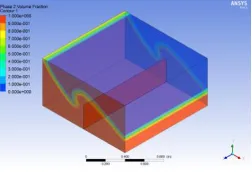
[image:2.612.383.508.287.367.2]Figures: 4.1 to 4.7 shows the sloshing of the liquid in tank filled with 60% Volume the result obtained from case 1 with one baffle before and after acceleration with time steps showed. The figures shows the motion of fluid occurs immediately after vehicle accelerated as half of the tank is empty. In this case, the filling level is reduced to 60% of the tank height, which results in the formation of a travelling wave and large air pockets are observed when the wave breaks into a wall of the baffle.
Figure 4.1 volume fraction of liquid with one baffle at 0.01sec
[image:2.612.377.509.392.475.2]The figure below shows the slosh of the 60%volume liquid with one baffle, It has been observed that the wave start to break at the location of baffle, which is due to the hitting of the wave on the wall of the baffle, and hence causing the strength the slosh decreases.
[image:2.612.116.223.440.508.2]Figure 4.2 volume fraction of liquid with one baffle at 0.1sec
Figure 4.3 volume fraction of liquid with one baffle at 0.15sec
[image:2.612.382.508.549.635.2]The complete break of the slosh wave was observed at 0.2 sec of excitation, the slosh wave ends at the wall of the baffles and a new wave was observed to be generated from the wall.
Figure 4.4 volume fraction of liquid with one baffle at 0.2sec
International Journal of Emerging Technology and Advanced Engineering
Website: www.ijetae.com (ISSN 2250-2459,ISO 9001:2008 Certified Journal, Volume 5, Issue 12, December 2015)
[image:3.612.94.241.239.322.2] [image:3.612.363.525.248.354.2]220
Figure 4.5 volume fraction of liquid with one baffle at 0.3sec [image:3.612.94.242.346.428.2]Figure 4.6 volume fraction of liquid with one baffle at 0.4sec
[image:3.612.363.524.380.481.2]Figure 4.7 volume fraction of liquid with one baffle at 0.6sec
Figure 4.8 volume fraction of liquid with one baffle at 1sec
Figure 4.9 volume fraction of liquid with one baffle at 1.5sec
Figure 4.10 volume fraction of liquid with one baffle at 1.7sec
[image:3.612.92.244.453.535.2]Figure 4.11 volume fraction of liquid with one baffle at 2sec
Figure 4.12 volume fraction of liquid with one baffle at 3sec
Figure 4.13 volume fraction of liquid with one baffle at 4sec
[image:3.612.364.522.507.599.2] [image:3.612.92.244.560.647.2]International Journal of Emerging Technology and Advanced Engineering
Website: www.ijetae.com (ISSN 2250-2459,ISO 9001:2008 Certified Journal, Volume 5, Issue 12, December 2015)
221
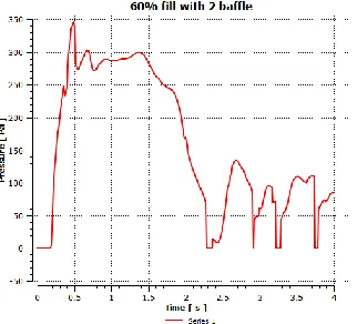
This occurs because when the liquid mass flows from one side to other, the inner liquid moves slightly slower and quietly as compared to the free surface liquid. The free surface layers suffer maximum displacement in the vertical direction, and also experience hydraulic jump on hitting the walls. The highest pressure experienced is 420 Pa with the lowest being 0 Pa. This shows a difference of 420 Pa as observed with 60% fill level. The increase in maximum pressure happens as a result of the increase in the liquid column near the wall.
Figure4.14: variation of pressure with respect to time for 60% fills of liquid with one baffle
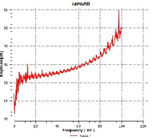
Figure4.15: variation of Amplitude with respect to frequency for 60% fills of liquid with one baffle
CASE 2: 60% FILL WITH -2 BAFFLES
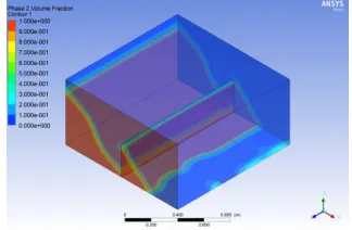
[image:4.612.373.517.136.230.2]It is observed that the surface displacement varies increase in number of baffles. This is because, on hitting the baffles, the kinetic energy of the moving fluid gets dissipated and therefore the fluid does not have enough energy to climb up. The phenomenon of sloshing, which is defined as the displacement of unrestrained free surface, eventually decreases thus proving the earlier research on use of baffles as the most possible suppression technique of sloshing. In the present study, the appropriate number of baffles was obtained which proves to be more efficient.
[image:4.612.95.247.255.350.2]Figure 4.16 volume fraction of liquid with two baffles at 0.01sec
Figure 4.17 volume fraction of liquid with two baffles at 0.2sec
Figure 4.18 volume fraction of liquid with two baffles at 0.4sec
[image:4.612.375.515.382.487.2] [image:4.612.96.248.384.522.2]International Journal of Emerging Technology and Advanced Engineering
Website: www.ijetae.com (ISSN 2250-2459,ISO 9001:2008 Certified Journal, Volume 5, Issue 12, December 2015)
[image:5.612.73.263.132.232.2] [image:5.612.80.258.258.359.2]222
Figure 4.20 volume fraction of liquid with two baffles at 1.4sec [image:5.612.373.516.261.357.2]Figure 4.21 volume fraction of liquid with two baffles at 1.8sec
Figure 4.22 volume fraction of liquid with two baffles at 2.1sec
[image:5.612.79.256.385.487.2]Figure 4.23 volume fraction of liquid with two baffles at 2.6sec
Figure 4.24 volume fraction of liquid with two baffles at 3sec
Figure 4.25 volume fraction of liquid with two baffles at 4sec
The irregular change of pressure in the given time periods could be attributed to the setup vibrations and other unknown forces. The observations show that the two baffles are the best choice as they reduce the pressure to the maximum extent. This happens because the two baffles not only suppresses the velocity of impact of the fluid at the walls but also retards the vertical motion of the liquid near the other two adjacent walls, thereby suppressing the wave amplitude. The turbulence is created due to its sharp edges at all the walls and thereby, dissipating the violent energy to all the walls. This reduces the stress on the impact walls.
[image:5.612.367.528.512.658.2] [image:5.612.109.264.577.675.2]International Journal of Emerging Technology and Advanced Engineering
Website: www.ijetae.com (ISSN 2250-2459,ISO 9001:2008 Certified Journal, Volume 5, Issue 12, December 2015)
223
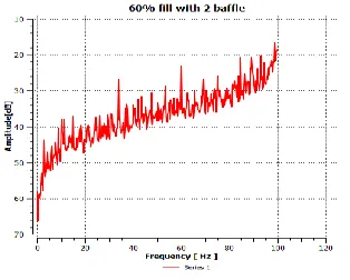
Figure4.27: variation of Amplitude with respect to frequency for [image:6.612.92.249.133.259.2]60% fills of liquid with two baffles
Figure 4.28 Stream lines of velocity of sloshing for two baffles
V. CONCLUSION &FUTURE SCOPE
Maximum velocity of slosh of the liquid has been decrease from 2.66m/s for one baffle to 2.10m/s for two baffles. Maximum Pressure has been considerably decreased from 420Pa for one baffle to 350 Pa for 2 baffles. The amplitude of vibration was observed to be 68m2/s for tank with one baffle where as 62 m2/s for tank with two baffles.
It is seen that using baffles generally leads to a decrease in the liquid level variations (the maximum liquid rising), and using more baffles results in more decrease in liquid level rising. Therefore, 2 baffles are recommended to be used in tanks of the sizes around the size of the studied tank. The present work can be extended by varying the height of the baffles and thickness of the baffles which lead to further study.
REFERENCES
[1] J.H. Jung, H.S.Yoon , C.Y.Lee, S.C.Shin (2012), ―Effect of the vertical baffle height on the liquid sloshing in a three-dimensional rectangular tank‖, Ocean Engineering. Vol 44: 79–89.
[2] V. Singal , Jash Bajaj, Nimish Awalgaonkar, Sarthak Tibdewal (2014), ―CFD Analysis of a Kerosene Fuel Tank to Reduce Liquid Sloshing‖, Procedia Engineering. Vol 69: 1365 – 1371
[3] Krit Threepopnartkul, Chakrit Suvanjumrat, ―The Effect of Baffles on Fluid Sloshing inside the Moving Rectangular Tank‖, Journal of Research and Applications in Mechanical Engineering. Vol. 1 No.2 [4] Mahmood Hosseini, Hamidreza Vosoughifar, Pegah Farshadmanesh
(2013), ―Simplified Dynamic Analysis of Sloshing in Rectangular Tanks with Multiple Vertical Baffles‖, Journal of Water Sciences Research, ISSN: 2251-7405 eISSN: 2251-7413 Vol.5, No.1: 19-30. [5] Dongming Liu, Pengzhi Lin, (2009). ―Three-dimensional liquid
sloshing in a tank with baffles‖, Ocean Engineering. Vol 36: 202– 212
[6] M. A. Goudarzi · S. R. Sabbagh-Yazdi · W. Marx, (2010), ―Investigation of sloshing damping in baffled rectangular tanks subjected to the dynamic excitation‖, Bull Earthquake Eng. Vol 8:1055–1072.
[7] M. Lsaacson, S. Premasiri., Hydrodynamic damping due to baffles in a rectangular tank, Canadian Journal of Civil Engineering, 28(4), pp.608- 616, 2001.
[8] D. Liu, P. Lin., A numerical study of three-dimensional liquid sloshing in tanks, Ocean Engineering, 36, pp. 202-212, 2009. [9] Mi-An Xue, Jinhai Zheng, Pengzhi Lin, (2012), ―Numerical