International Journal of Emerging Technology and Advanced Engineering
Website: www.ijetae.com (ISSN 2250-2459,ISO 9001:2008 Certified Journal, Volume 5, Issue 6, June 2015)
15
Modeling of Hydro-Mechanical Answer to Around a
Pressuremeter Probe
Ouabal Houari
1, Zadjaoui Abdeldjalil
21,2
Civil Engineering Department, University of Tlemcen, Algeria
Abstract— This paper presents the results of numerical
simulation of the pressuremeter test performed in a massive area has held horizontal account the interaction fluid phase soil (soil consolidation). The objective is the determination of pressuremeter characteristics the module and the limit pressure. The results are compared with previous work (Soegiri, 1991) and the analytical results, simulations are made using a computer code based on the finite element method (Plaxis) with an elastoplastic behavior laws namely Cam Clay.
Keywords—Pressiomter, Consolidation, Coupled
hydro-mechanical, Settlement.
I. INTRODUCTION
The building of a structure based on superficial foundations became increasingly common, hence the need for reliable methods for the design and calculation of these foundations.
Beyond the problem of choosing a law of behavior appropriate to the problem at hand, determining the parameters of the law of value remains a critical step for geotechnical modeling. These parameters can be identified from laboratory tests and / or testing in place, or with both types of tests.
In this article there is great interest on the Ménard pressuremeter tests; which is a massively used nowadays in the latter unit foundation projects was invented by Louis Menard (1955 and 1959). The approach is usually to take the test on one hand the pressuremeter modulus, and secondly the limit pressure.
The purpose of this study is to make a numerical interpretation of the results of pressuremeter test in a load held solen account the interaction stage liquid-ground, end to meet a certain number of questions about the possible development of the limit pressure and changes in pore pressure to turn the probe
II. HISTORY AND DEVELOPMENT OF PRESSUREMETER
The pressuremeter test was invented by German Kögler the 1930s, in order to measure a soil deformation modulus. Due to the technology of the time, the unit was not operational.
Furthermore, the inventor has failed to correctly interpret the results and the unit was immediately abandoned. In 1954 a young French engineer, Louis Ménard, took up the idea in the refining: the inflatable cylinder Kögler, he added two guard cells to the central measuring cell, avoiding the expansion of the drilling and thus making interpretable test. The unit became operational quickly because of advances in technology: Rubber cells consist admitting large deformations and especially invention of semi-rigid plastic tubing making possible the realization of in-depth testing. But the contribution of Louis Ménard has focused on defining Pressuremeter soil characteristics and developing rules of interpretation for the design of foundations using these parameters (Amar and Jézéquel 1998).
III. THEORETICAL OVERVIEW ON THE CONSOLIDATION OF SOILS
However rigorous definition of soil consolidation process can be presented only through the principles enunciated by Terzaghi (1923), who first came out of the practices of globally analyze the behavior of the massif, and considered a solid floor as consisting of two phases, the skeleton and water. This separation allowed him, after writing the equations relating to each of the two phases, the calculations presented in drained and undrained conditions are only extreme conditions, the reality will generally be in intermediate conditions for which the generation of the pore pressure will depend crucially on the speed of the solicitation and the permeability of the medium. Especially in the classic test, loading for a given pressure is applied for a minute, so the whole test lasts between 10 minutes and 20 minutes. Given the duration of the pressuremeter test, it seems likely that there will be a change of pore pressure due to consolidation.
International Journal of Emerging Technology and Advanced Engineering
Website: www.ijetae.com (ISSN 2250-2459,ISO 9001:2008 Certified Journal, Volume 5, Issue 6, June 2015)
16
A. Mathematical formulation
Consider the expansion of a pressiometric probe in a homogeneous soil with a plane strain hypothesis. In view of the symmetry about the axis of the probe increases the stresses in the directions and z in the r direction, θ and z are the main (Figure 1). The only variables remaining in the problem description of a pressuremeter probe are:
r : radial coordinate, Ur : radial displacement, : main constraints
The calculation assumptions taken into account are:-
The
plane strain assumption implies that the deformation in the axis of the probe is zero pressiometric ( ).- The interstitial water is assumed incompressible.- The test is undrained soil conditions and any element
keep a constant volume during expansion ( ). - Postulate Terzaghi (effective stress):
(1)
With
- components of the total stress - components of effective stress - pore pressure
Figure 1. The equilibrium of an element of the soil around the pressuremeter probe (Bahar ,Belhassani, 2015)
B. Solving equations of a problem torque (fluid-solid interaction)
Equations for the soil skeleton
Balance Equation: In the case of pressuremeters the equilibrium equations are written:
(2) Solid fluid interaction
The Terzaghi relationship is:
(1)
Boundary conditions
The boundary conditions on the skeleton:
Equations related to interstitial fluid and flow
Continuity equation
In the case of one pressure meter is under conditions of axial symmetry, plane strain ( ) and radial flow. All variables depend only on r. Based on the assumption of an incompressible interstitial fluid, the change in total volume is equal to the volume of water coming out of the ground. The continuity equation is expressed as follows:
(3)
Darcy law
This law is expressed by the equation:
(4)
( : Permeability tensor)
Taking into account the isotropy hypothesis medium was:
(5)
With:
H = hydraulic load, in which we neglect the dynamic effect. V = the mean flow velocity
k = permeability coefficient (scalar) = the unit weight of water
Combining the last two equations are obtained:
(6)
Boundary conditions
In the case of pressure meter, a zero flow rate is set at the sensor membrane ( ),(Impermeability of the membrane). therefore : Vi = O therefore
International Journal of Emerging Technology and Advanced Engineering
Website: www.ijetae.com (ISSN 2250-2459,ISO 9001:2008 Certified Journal, Volume 5, Issue 6, June 2015)
17
Coupling solid - fluid
The consolidation problem addressed by the finite element program corresponds to a coupling between the behavior law of the soil skeleton and pore water flow through porous media equations governing. The system to be solved is then written:
(8)
In these expressions, R and K represent the stiffness matrixes respectively corresponding to the deformability and permeability of the solid, and C. a switching matrix; F denotes the loading vector and the vector of Q taxed rates.
IV. NUMERICAL STUDY
A. Geometric and geotechnical characteristics of the model
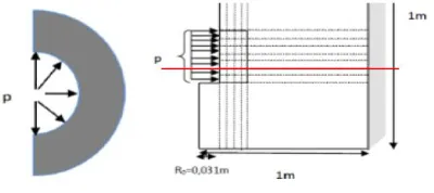
[image:3.612.76.276.384.473.2]The problem is treatedin plane strain in the plane (O, X, Y), with the conditions to travel in limits:
Figure 2: Geometry problem
For this study we used an elastoplastic behavior laws, Cam-Clay model this model is completely defined by parameters (ν, λ, k, M, e0, pco) (Mestat and Magnan, 1997; Mestat, 1993 Khemissa et al., 1993).
The calculation parameters are shown in Table I, they are derived from parameters found in the literature and correspond to a clay (Soegiri 1991).
Table I
Parameter set (Soegiri 1991).
V. SIMULATING THE PRESSUREMETER TEST
A.Basic assumptions
The general assumptions taken into account are: 1) The simulations are performed in small deformations; 2) The test is analyzed in undrained conditions (total stress) and 3) The mode of deformation of the pressuremeter probe deformation planar.
B. Pressuremeter probe Dimensions
A total height of sensor H = 70 cm, and diameter D = 62 mm, with a height of the measuring cell of 40 cm, 15 cm and two guard cells.
The pressuremeter tests are simulated at various points and positions the type of pressuremeter pressuremeter is used with the prior drilling. We model a soil volume by taking 15-node elements considering the axisymmetric case with respect to the vertical axis. Mesh dimensions are given in Figure
C. Boundary conditions and loadings
The soil is free on the vertical walls of drilling and vertical movement is possible on the two vertical borders. With regard to loading, two loads are involved in this problem:
1) A load "type A" due to the weight of the land prior to drilling for which there are two different loads: a) a uniform vertical load applying down-hole drilling and equal to .z , with being the specific weight of the land and z being the depth of drilling. b) a horizontal load varies linearly with depth and applying on the vertical wall of the drill hole, value r being the coefficient of land at rest (Figure 4). This loading will then obtain uniform initial stress state throughout the soil mass. (Al Husein 2001).
2) A load "Type B" loading that simulates the loading applied by the probe on the ground (Figure 4). This loading is applied radially on a length equal to the length of the probe, in downhole. (Al Husein 2001).
P
ara
m
eter
γ (kN /m3
ν C
(kpa)
λ k M e0 pco K
(m/s)
[image:3.612.38.317.589.687.2]International Journal of Emerging Technology and Advanced Engineering
Website: www.ijetae.com (ISSN 2250-2459,ISO 9001:2008 Certified Journal, Volume 5, Issue 6, June 2015)
[image:4.612.71.273.119.274.2]18 Figure 3: Mesh 3D plane and around pressiométre.et both loading
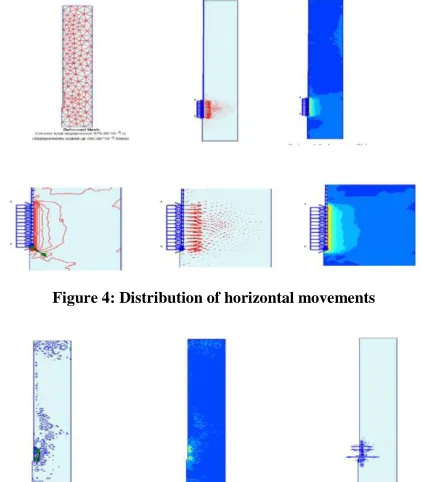
VI. RESULTS AND DISCUSSION
The figure 4 shows for the Cam-Clay models the results of radial displacements (horizontal movements) .D'une similar way we analyze the distribution of horizontal displacement Color Tone, We have shown in a vertical cutting changes in these last one Note that the horizontal displacement are almost zero when the distance from the borehole probe pressuremeter.
Pressiometric the expansion curves for various depths are shown in Figure 4 (horizontal solid) to the Cam-Clay model amended. These different tests are used to trace the profile of the conventional limit pressure according to the depth Y of the test. The test results depend only on the Y towards which it is made.
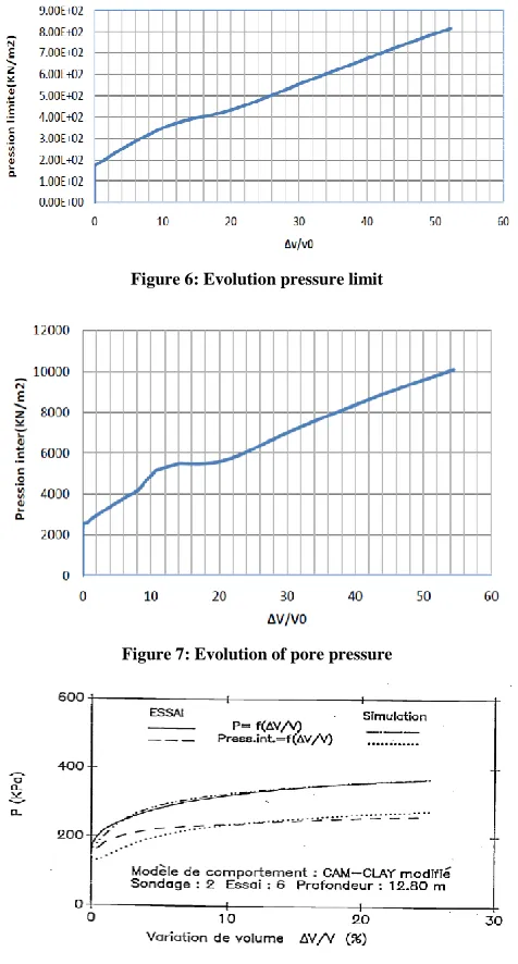
These results are consistent with the classic curves of the pressuremeter test (Figure 6), the curves exhibit a marked curvature. For greater depths, they become almost linear. Pressuremeter V/V0 = f(p-p0) , where V0 is thecurves
will be given in the form initial volume of the probe, its current volume V p0 initial horizontal radial stress at the probe, and (p -p0) is the pressure applied to the probe to the considered load increment. The current volume V of the probe is obtained directly in the case of massive horizontal (Axisymmetric model).
For comparison with the work of (Soegiri, 1991) and the results, which we did with Plaxis, (limit value (), and evolution of pore pressure) we see that the results are comparable to conventional pressuremeter curves perspective qualitative (shape of the curve). quantitative standpoint (slope of the curve).
A. Evolution of pore pressures in the Massif
Up 'at this point we have to mention the mechanical parameter, as a change of the engineer (pi) pore pressures involves emblem on the principle of Terzaghi bishop or a change in the effective stress which gives a mechanical effect c' For that reason we presented the evolution of pore pressure (pi) in time by delaying section With time it decreased pore pressure (p) so i the water pressure induced by digging drilling the probe are pressuremeter completely dissipated.
This progressive reduction in pore pressure was observed, interpret this phenomenon considering that the drill acts as a drain causing the groundwater flow toward drilling and therefore a consolidation of the massif.
[image:4.612.337.548.342.583.2]Note that in Fascicle 62 the calculation of the equivalent pressure limit is based on a linear approximation of the pressure limit as a function of depth.
Figure 4: Distribution of horizontal movements
International Journal of Emerging Technology and Advanced Engineering
Website: www.ijetae.com (ISSN 2250-2459,ISO 9001:2008 Certified Journal, Volume 5, Issue 6, June 2015)
[image:5.612.50.288.145.588.2]19 Figure 6: Evolution pressure limit
Figure 7: Evolution of pore pressure
Figure 8: Evolution limit pressure and pore pressure (Soegiri, 1991)
VII. CONCLUSION
Analysis of pressuremeter test taking into account the evolution of pore pressures has allowed to highlight the influence of the permeability of the medium and the loading speed.
We found that modeling the pressuremeter test (determination of pressuremeter characteristics) digitally is much more delicate, Based on these results, we see that numerical simulation with Plaxis, which we did, gave results comparable to conventional pressuremeter curves qualitatively (shape of the curve).
Regarding the analytical and numerical comparison of the limit (pl), numerical simulations we made with the
modified Cam-Clay model, data have comparable results to the analytical values quantitatively (slope of the curve) .
It is clear that this result still requires improvement in order to make practical conclusions in relation to the practice of engineering: experimental aspects and calculation of shallow foundations on a slope according to standards and regulations
REFERENCES
[1] Al Husein M. (2001) Study of the delayed behavior of soils and geotechnical structures. PhD thesis, University Joseph Fourier. (France).
[2] Amar S., Jézéquel JF (1998) Mechanical properties of soils determined in place. C 220. Techniques Engineering, Construction Treaty.
[3] S. Amar, Jezequel JF (1972) Field testing and laboratory on cohesive soils, comparison of results. Liaison Bulletin CEA, Paris, No. 58. [4] S. Amar, Jézéquel JF (1985), pressuremeter test. Draft test method.
LCP. # 15.
[5] R. Bahar, Belhassani O. (2015) modeling of cyclic pressuremeter test and identification of soil behavior settings. ISP7-PRESSIO 2015 pages (271-279)
[6] Baguelin F, Jezequel JF (1972) Expansion of cylindrical probes in cohesive soils. Liaison Bulletin Laboratory of Bridges and Roads, No. 61, pp.189-201.
[7] F. Baguelin, Jezequel JF (1973) The self-boring pressuremeter. Annals of ITBTP.
[8] Issue 62 - Title V. (1993). Design technical requirements and design of foundations for civil engineering works. General Technical [9] Conditions of Contract applicable to public works contracts.
Ministry of equipment, housing and transport, official texts No. 93-3,182p.
[10] Mr. Khemissa, JP Magnan, Josseaume H. (1993) Study of mechanical properties of the clay Guiche (Adour valley). Studies and research LPC, GT series, No. 153, 204 pages.
[11] JP Magnan, Mestat P. (1997) Behavior laws and modeling of soil. C218. Engineering techniques. Construction Treaty.
[12] Mestat P. (1993) geomaterials behavior Laws and modeling using the finite element method. ER LPC. GT series. 193 pages.