A profiled structure with improved low
frequency absorption.
Wu, T, Cox, TJ and Lam, YW
http://dx.doi.org/10.1121/1.1412443
Title
A profiled structure with improved low frequency absorption.
Authors
Wu, T, Cox, TJ and Lam, YW
Type
Article
URL
This version is available at: http://usir.salford.ac.uk/429/
Published Date
2006
USIR is a digital collection of the research output of the University of Salford. Where copyright
permits, full text material held in the repository is made freely available online and can be read,
downloaded and copied for noncommercial private study or research purposes. Please check the
manuscript for any further copyright restrictions.
A profiled structure with improved low frequency absorption
Tao Wu, Trevor J. Cox,a)and Y. W. Lam
School of Acoustics and Electronic Engineering, University of Salford, Salford M5 4WT, United Kingdom
共Received 26 June 2001; accepted for publication 17 August 2001兲
It is possible to obtain good absorption from Schroeder diffusers if suitable alterations to the design are made. Interestingly, previous work has shown that good absorption appears possible below the design frequency when the diffusers are poorly constructed. This has inspired the design of a profiled absorber using perforated plates in some wells; the absorber has extended bass response. The paper presents a theory for the enhanced absorption and the important design parameters are discussed. Good agreement is shown between the prediction model and impedance tube measurements. The design of this absorber was first carried out using a numerical optimization, although a simplified design procedure is also outlined which is almost as good. The results clearly show that this type of profiled absorber extends the absorption at low frequencies while maintaining the good absorption at mid frequencies as well. © 2001 Acoustical Society of America. 关DOI: 10.1121/1.1412443兴
PACS numbers: 43.55.Ev, 43.55.Dt 关JDQ兴
I. INTRODUCTION
Schroeder diffusers have been widely used in concert halls, theatres, and studio control rooms.1There is evidence, however, of significant absorption when the diffusers are poorly designed.2 Kuttruff,3 Mechel,4 Fujiwara et al.,5 and Wu et al.6 theoretically and practically investigated the ab-sorption mechanism. Kuttruff presented the concept of addi-tional air flow between the wells as the source of the excess absorption, although he could not obtain a prediction model which explained the high absorption measured by others. Mechel thoroughly discussed the absorption effect for the near field as well as the directivity for the far field, although his studies lacked direct experimental verification. Further-more, Mechel indicated the possibility of a low-frequency band absorber by bending the wells, and using the primitive root rather than the quadratic residue sequence to gain better absorption. Wu et al. brought together measurement and pre-diction to provide proper evidence that the strong coupling between the wells is responsible for the high absorption. This was used to develop a new profiled absorber by arranging the depths of wells in one period properly using numerical opti-mization.
High absorption at low frequencies is the most difficult to achieve from these profiled devices, consequently, the challenge tackled in this paper is to get more absorption bandwidth from a given length. Interestingly, in the paper by Fujiwara,5 it was reported that poorly constructed structures could provide high absorption below the lowest resonant fre-quency. It is speculated that this additional absorption came from cracks in the well bottoms forming Helmholtz resona-tors with air cavities behind. This inspired the idea that using perforated plates in some wells could significantly extend the absorption range towards the lower frequencies by adding mass to the system and so lowering the resonant frequency. While the research presented here was in progress, Fujiwara7 published a paper which contained measurement
results on a structure with Helmholtz resonators in the wells, i.e., using a similar technique to add mass and to get better absorption in a low frequency range. Fujiwara presented no verified prediction model or design methodology for these structures; it appears the design was formed by trial and er-ror. What is new in the paper below is a prediction model validated against measurement; a more complete understand-ing of the effects of the different elements in the absorber, and analytical design methodologies which will be used to get the best possible absorption from this structure.
First, the prediction model is presented including the effect of a perforated plate at different positions in the well. The simplest constant length structure with perforated plates in the wells has been optimized to obtain better absorption without any resistant layer on the top. However, as will be shown, this structure cannot provide wide frequency band absorption. It is essential to include different depth wells to get wide frequency range absorption. A numerical optimiza-tion is performed to obtain better absorpoptimiza-tion by adjusting the position of the perforated plates in the wells, and the depths of the wells. The theoretical results have been compared with experimental results, and good agreement achieved. The sig-nificant improvement at low frequency range is clearly shown when comparing this kind of absorber with profiled absorber without in-well perforations. The final part of the paper investigates a more straightforward design methodol-ogy than numerical optimization. It is shown that by follow-ing a couple of simple principles good absorption can be achieved without resorting to numerical optimization.
II. SINGLE WELL MODEL
A. The impedance of a perforated panel
Perforated panels have been used for some years in con-junction with acoustic compliance, and their ability to pro-duce absorption at low frequencies, especially with resistive material, is well known. The perforated plates can be consid-ered as a lattice of short tubes, where the pitch of adjacent tubes is small compared with wavelength of propagating
sound, but larger than the hole diameter. It is assumed that when sound flows through the holes, there is no motion in the plate itself, and the hole radius is larger than the bound-ary layer thickness. Then the specific acoustics impedance of the perforated plate is8
zp⫽rm⫹jm 共1兲
and
rm⫽
冑
8冉
1⫹ t2a
冊
, 共2兲m⬇
冋
t⫹2␦a⫹冑
8
冉
1⫹t
2a
冊
册
, 共3兲where is the air density, is the angular frequency of propagating sound, is porosity of the plate, t is the thick-ness of the plate, a is the radius of the holes, ␦ is the end correction factor 共⬇0.85兲, and the last term is due to the boundary layer effect, in whichis the kinemetric viscosity of the air (⬇15⫻10⫺6m2/s).
B. The impedance at the entrance of a well
The impedance is needed at the entrance of a well con-taining a perforated plate and with resistive material at the well entrance. The well width of a profiled absorber is nar-row compared with diffusers to provide more absorption, therefore the energy losses caused by viscous and thermal conduction in the wells cannot be neglected. In general, the well width bⰆ/2, whereis the wavelength of the sound, so that only fundamental modes are considered to propagate in each well. The propagation number in the wells is9
kt⬇k⫹ k
2b共1⫺j兲关dv⫹共␥⫺1兲dh兴, 共4兲
where k⫽/c, c is the speed of sound. dv,dh are the thick-ness of the viscous and thermal boundary layers, respec-tively, these can be found from Eq.共5兲of Ref. 6. The wells should not be made too narrow, however, because then the resonance共s兲would be destroyed. Considering a well length ln, a perforated plate is fixed at ln1from the opening of well. The impedance on the opening of the well can be derived by the multilayer transfer matrix as
zw⫽cz1coth共j ktln1兲⫹共c兲
2
z1⫹c coth共j ktln1兲
⫹r, 共5兲
where r is the resistivity of the material at the well entrance and z1 is the total impedance at ln1of a perforated plate and the cavity it covered. z1 can be calculated by the following
equation:
z1⫽rm⫹j共m⫺c cot共kt共ln⫺ln1兲兲兲. 共6兲 When no perforated plate is used in the well, the entrance impedance simplifies to
zw⫽r⫺jc cot共ktln兲, 共7兲
where ln is the depth to the well bottom.
C. Effect of perforated plate at different positions in the well
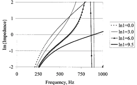
As can be seen from Eqs.共5兲and共6兲, the position of the perforated plate in a well is important for the resonant fre-quency. Changing the position of perforated plate from bot-tom to opening in the well, the first resonant frequency of the well is gradually decreased, from the first resonant frequency of the well without perforated plate to the frequency with perforated plate on the top. This gives us a possibility to tune the well by adjusting the positions of the perforated plates. An example is given in Fig. 1, the width of well is 6 mm, length 10 cm, and the parameters of perforated plate are
⫽5%, a⫽1 mm, t⫽5 mm, the plate’s position in the well is ln1⫽9.5 cm, 6.0 cm, 3.0 cm, and 0.0 cm, respectively. The first resonant frequency changes from 900 Hz to 415 Hz as expected. While this change of about an octave enables the wells to be differently tuned, it will be shown later that this is not a sufficient variation and so some wells without perfora-tions are also needed.
III. ABSORPTION BY A PROFILED ABSORBER
A. Theoretical prediction
Profiled absorbers are periodic surface structures with rigid constructions, which consist of wells separated by thin walls. The wells have the same width, but different depths in one period.
The analysis method used in Ref. 6 is still valid for the structure employing perforated plates in wells. The structure is illustrated in Fig. 2. For the one-dimensional absorber, the sound field in front of the absorber is decomposed into the incident plane wave pe(x,z) and scattered field ps(x,z) as follows:
p共x,z兲⫽pe共x,z兲⫹ps共x,z兲 共8兲
and
pe共x,z兲⫽Peej共⫺xkx⫹zkz兲,
共9兲 ps共x,z兲⫽
兺
Anej共⫺xn⫺z␥n兲, [image:3.612.326.547.34.172.2]where kx⫽k sine, kz⫽k cose, and n⫽kx⫹n(2/T), ␥n⫽⫺jk
冑
关sine⫹n(/T)兴2⫺1, T is the width of one period.FIG. 1. Comparison of the imaginary part of impedance when moving a perforated plate form bottom to top of a 10 cm well. Distance from top of well to perforated plate, ln1, shown in legend.
The coefficients, An, are solved by applying the boundary condition of the periodic impedance on the surface of the absorber.6The absorption coefficient of the absorber is then
␣共e兲⫽1⫺
冏
A0Pe
冏
2
⫺ 1
cose
⫻
兺
冏
AnsPe
冏
2
冑
1⫺共sine⫹ns/T兲2. 共10兲The summation runs over radiating spatial harmonics only. For normal incident sound and narrow wells, when sine⫹/T⭐1, there are only first order reflections, therefore the equivalent normalized impedance on the surface of the structure can be derived from
ze⫽
1⫹A0/ Pe
1⫺A0/ Pe. 共11兲
B. Experimental result
In order to verify the above prediction model, a one-dimensional sample made from aluminum was built inside an impedance tube which had a cross-section size 54
⫻54 mm. The parameters of perforated plate are porosity
⫽5.34%, t⫽5 mm, a⫽1 mm. Because of the impedance tube’s size, the sample is limited to seven wells in one pe-riod, width of well 6 mm, well separator thickness 1 mm. As we will see later, this construction was optimized for a low frequency profiled absorber, which had a resistive layer on the top of the structure to enhance the losses due to coupling between the wells. Here, it was first measured without the resistive layer to validate the prediction model.
The measurement was carried out in an impedance tube. The procedure was the same as in previous paper,6which is similar to the two microphone standard technique. It is im-portant to remember that in the theoretical predictions the mirror-image effect caused by impedance tube walls has to be included.
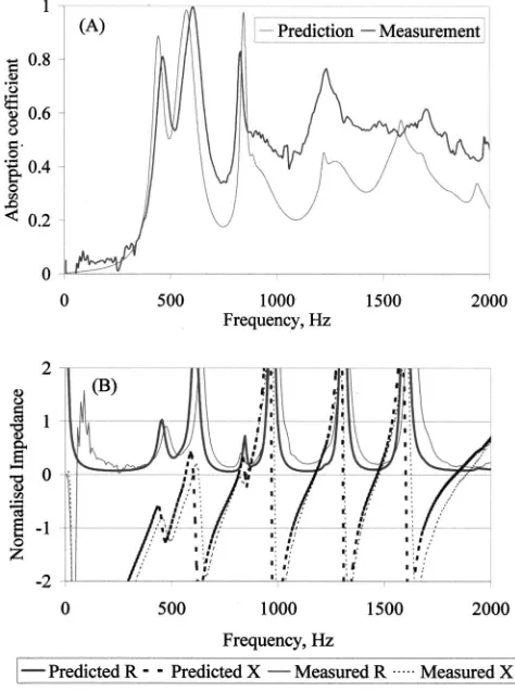
For conciseness, the following abbreviations in the nor-malized impedance graphs will be adopted throughout this paper. The real part of normalized impedance will be R, and the imaginary part X. The comparisons between predictions and measurements of absorption and impedance are shown
in Fig. 3. Reasonably good agreement can be seen for the imaginary part of impedance and other parameters in the low frequency range. The slightly higher absorption at middle frequency are likely to be due to unavoidable gaps during the construction and installation of sample. The measurement results demonstrated the validation of prediction model for this kind of structure.
IV. CONSTANT LENGTH ABSORBER WITH PERFORATED PLATES
With a validated prediction model, it is possible to use a trial and error search on a computer, a numerical optimiza-tion, to find the best design. The computer can change the absorption by moving the perforated plate in the wells and so tune the resonant frequency. The computer intelligently searches using a downhill simplex method;10the goal being to find the absorber with the highest average absorption. A similar technique was used in Ref. 6.
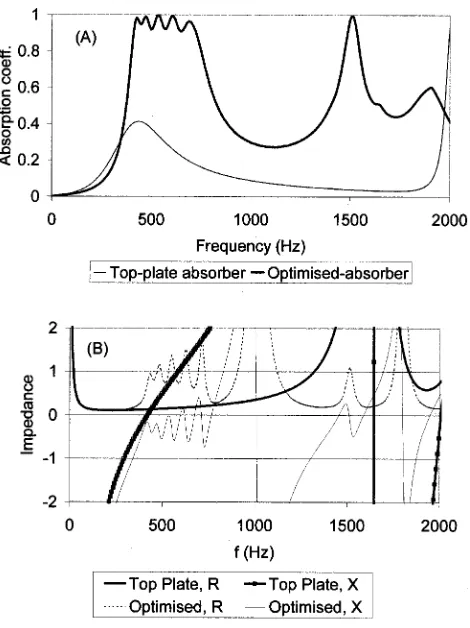
The absorption coefficient and impedance on the surface of structure combining constant length absorber and perfo-rated plates are calculated for two cases: ‘‘uniform’’ con-struction with the perforated plate on the top of the structure, and ‘‘optimized’’ construction with the optimized structure with perforated plates at different positions in each well. The parameters are for constant length absorber, N⫽7 wells in one period, b⫽6 mm, w⫽1 mm, and well length ln
[image:4.612.67.280.34.197.2]⫽10 cm; for the perforated plate, ⫽5%, a⫽1.0 mm, t
[image:4.612.317.554.39.357.2]FIG. 2. One period of profiled sound absorber with perforated plates.
⫽5 mm. The results are shown in Fig. 4, and position se-quence ln1 of perforated plates for optimized construction are 3.1, 0.1, 0.0, 7.2, 4.9, 6.2, 8.2 cm.
From Fig. 4共a兲, it is clearly seen that the absorption of the optimized construction is higher than the construction with the perforated plate on the top across the whole fre-quency range, and particularly at low frequencies, where the absorption coefficients are nearly 1. Even at the first resonant frequency of the uniform construction, where every well has contributed a resonance at that particular frequency, the ab-sorption is still less than the optimized solution. Looking into the impedance graph Fig. 4共b兲, the optimized structure cre-ated a nonuniform surface impedance that scatters sound. The scattering enhances the coupling between the wells, which provides higher resistance when compared with the uniform construction. Although the absorption at low fre-quency is high in the optimized absorber, elsewhere is low. This is because the first resonant frequencies have been re-stricted within a small range, which is from the resonant frequency of structure with the perforated plate on the top to it on the bottom, the coupling in that frequency range is strong, elsewhere is poor. This is the problem alluded to before, where the frequency range of a perforated well could be tuned over what was shown to be only about an octave. This indicates that, in order to widen the frequency band, a variable depth sequence is necessary to provide better cou-pling over the whole frequency range of interest.
V. WIDEBAND ABSORBER
A. Theoretical discussions
From the investigations of Mechel4 and the authors,6 a better absorber can be obtained by properly placing the reso-nant frequencies across the whole frequency range of inter-est, and applying a proper resistant layer on the top of the structure. In Sec. IV, high absorption at low frequencies had been obtained, however, the frequency bandwidth was nar-row. Changing some wells with constant depth to variable depth can solve this problem. At the higher frequency range, optimizing the depth sequence of variable wells is sufficient to obtain well-distributed resonant frequencies without per-forated plates. Moreover, the use of perper-forated plates may cause strong coupling as is shown in Fig. 4共b兲, which makes it difficult to get uniform high absorption. Consequently, some variable depth wells with no perforated plates are used. The above discussion shows that, by optimizing the positions of perforated plates in the constant depth wells and the depth sequence of variable depth wells, the tuned and well-distributed resonant frequencies can be obtained. Great effort is needed to balance the number of constant wells and the number of variable wells in order to get better coupling at the low frequency range as well as high frequency range.
Again, a resistive layer is necessary to smooth the peaks and troughs seen in Fig. 4共a兲. The resistivity of the resistive layer must be chosen so that the well absorption is high over a reasonable bandwidth, so that the absorption troughs be-tween resonances are removed. Too large a resistivity value, however, would lead to an overly damped system and the peaks of absorption would be significantly lowered. This is illustrated in Fig. 5, where three absorbers with different re-sistive layers are compared. Each of these absorbers was optimized numerically for best performance. It can be seen that too little resistance 共55 Rayls兲 leads to an uneven per-formance, too much resistance 共400 Rayls兲 leads to over damping. 180 Rays performs best, and so is used.
[image:5.612.58.293.30.344.2]The perforated plate’s parameters should be chosen care-fully. As was seen in the previous paragraph, there is an optimum range of resistance that a well should offer. Conse-quently, overly small perforations should be avoided, other-wise additional resistive losses in the perforations is likely to detract from the performance.
FIG. 4. Comparison between the optimized structure with variable plate position and absorber with plate fixed at the top,共a兲absorption coefficient;
[image:5.612.321.553.32.181.2]共b兲normalized impedance.
FIG. 5. The effect of the resistivity of the resistive layer on the absorption coefficient of optimized absorbers.
The other parameters under the control of the designer are the number of wells in a period, and the maximum depth of a well. The maximum depth controls the lowest frequency absorbed and was arbitrarily fixed at 10 cm for this study. For the work that follows, N⫽7 was chosen because it en-ables direct comparison, both theoretically and experimen-tally, with previous work. It will be shown later, however, that the number of wells per period can be reduced.
The absorber and perforated plates having the same pa-rameters as the preceding section has been optimized. The number of constant wells with perforated plates is three, which were in wells 1, 4, 7; the number of variable wells without perforated plates is four; the resistant layer used has resistance 180 Rayls. In the range by the optimization pro-cess, the length of wells with perforated plates is fixed at 10 cm to guarantee a good performance at low frequencies; the variable depth’s length is restricted to a maximum of 10 cm. The performance is optimized up to 3 kHz. The theoretical result is shown in Fig. 6 together with corresponding mea-surement results. The depth sequence is shown in Table I. Figure 6 also shows the comparison between the new struc-ture and the optimized strucstruc-ture with the same parameters without perforated plates. It clearly shows the high absorp-tion is now achieved at lower frequencies.
The results above also provide some circumstantial evi-dence as to why poorly constructed diffusers have high absorption,5 with this high absorption occurring at low fre-quencies below the design frequency. There is a suggestion that this additional absorption must be due to coupling to air cavities. Hence, this emphasizes the need for well sealed
constructions when trying to manufacture phase grating dif-fusers with low absorption.
B. Experimental verifications
The tests are carried out in the impedance tube, the op-timization is repeated to take into account of mirror images, the resistance of the wire-mesh applied is 180 Rayls. The perforated plate is the same as tested in Sec. II B. The opti-mized structure is shown in Fig. 2.
Figure 6 also compares the prediction and the measure-ment of the sample and good agreemeasure-ment was found. In addi-tion, the perforated design is compared to an optimized con-figuration without perforations, details of which are given in Ref. 6. The addition of perforations enables the absorber to start working at a frequency nearly an octave lower than before. This demonstrates the usefulness of this new design in gaining additional low frequency absorption.
C. Number of wells per period, N
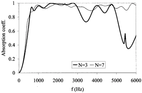
A series of optimizations were carried to gain an under-standing of the importance of the number of wells per period, N, to the quality of absorption obtained. Rather surprisingly, it was found that over the bandwidth being considered, up to 3 kHz, that an absorber based on N⫽3 works almost as well as one based on N⫽7. Figure 7 compares the performance for two optimized absorbers. Up to 3 kHz, the performance is comparable, but at a higher frequency, the higher N num-ber performs better. This happens because the density of resonances is significantly less for N⫽3 above 3 kHz when compared to N⫽7. Reducing N could be useful as it simpli-fies the design and so may reduce manufacturing costs.
[image:6.612.324.552.32.182.2]Simi-FIG. 6. Comparison of measurement and prediction for two types of ab-sorber.
[image:6.612.60.291.32.183.2]FIG. 7. Optimized absorbers for different number of wells per period N.
TABLE I. Some well sequence depths used共cm兲.
Sequence ln1 ln ln ln1 ln ln ln1
Optimized depth sequence 5.2 5.3 6.9 1 9.5 10 4.8
ln ln ln ln ln ln ln
Depths using new design technique, no perforations 10 4.9 3 6 4.2 7.6 3.7
ln1 ln ln1 ln ln ln1 ln1
[image:6.612.53.558.634.740.2]lar results were also found for absorbers without perfora-tions. Incidentally, the choice of the correct value flow resistivity for the resistive layer is even more important for low N absorbers.
VI. SIMPLER DESIGN METHODOLOGY
In previous work, a numerical optimization procedure was used to obtain the depth sequence used. This is a slow and complex procedure. Consequently, a more straightfor-ward design technique is desirable to practitioners. An anal-ogy with Schroeder diffusers can be drawn. While it has been long established that the quadratic residue sequence can be bettered by optimization, for example, Ref. 11, the sequence remains popular because of the ease of using a small number of simple design equations.
A simple design procedure for the absorber will be out-lined below, first the case of a profiled absorber with no perforated sheets will be considered as it is simpler, and then it will shown how this can be extended for the absorbers with perforated sheets.
A. Profiled absorber, no perforated sheet
At a first approximation, neglecting viscous boundary layer losses in the well, each well is a quarter wave resonator with resonant frequencies given by
f⫽共2m⫹1兲c 4ln
, m⫽0,1,2,3,... . 共12兲
To maximize the absorption it is necessary to evenly space these resonant frequencies over the design bandwidth avoid-ing degenerate modes, i.e., modes with similar resonant fre-quencies. This can be simply achieved by a trial and error process using a calculation tool such as a spreadsheet. Once the depths are determined, it is necessary to order them to maximize the losses due to energy flow between the wells. To achieve this, wells causing adjacent frequency reso-nances, should not be physically next to each other. This can be done quickly by hand. Table I shows an example depth sequence formed using this procedure.
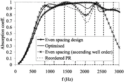
Figure 8 compares the performance of this design, to one produced using an optimizer.6 The performance of the absorber using the simpler design procedure is good. As
might be expected the optimization gives slightly better re-sults, but that design involved considerably more computa-tion and human effort. The resonance frequencies used dur-ing the design are also marked. The drop at high frequencies,
⬎2.5 kHz, occurs due to lack of resonances in the region above 3 kHz. To illustrate that the ordering of the wells is important, the graph also shows the results when the wells are stacked in ascending order. There is considerably less absorption, demonstrating the importance of exploiting the well coupling.
This procedure has similarities to a design approach for-warded by Mechel.4 He suggested placing adjacent-in-frequency resonant wells physically far apart to maximize coupling. He also suggested using a more even density of resonant modes by using a monotonically increasing well depth, like a ‘‘reordered primitive root sequence.’’ This sys-tem certainly improves on the quadratic residue sequence, but is not optimum. It is possible to get a more even mode density by a simple trial and error process than found with the reordered primitive root sequence 共a linearly increasing depth sequence does not give even modal density兲. Further-more ordering the wells in monotonically increasing depth does not maximize the spacing between adjacent resonant modes. Consequently, the new procedure can be seen as a better use and refinement of the principles laid down by Mechel. It also produces better absorbers. The ‘‘reordered primitive root sequence,’’ labeled ‘‘reordered PR,’’ is shown in Fig. 8. The new procedure produces a better absorber.
B. Profiled absorber with perforated sheets
The design is a little more involved when using perfo-rated sheets. The problem is that the resonance frequencies of the compound wells cannot be predicted using a formula as simple as Eq. 共12兲. Instead the resonances are located from the imaginary part of well entrance impedance, Eq.共5兲. It is not possible to analytically solve Eq. 共5兲 to gain the resonant frequencies, but a simple numerical method quickly yields the values. 共Again, during the design an assumption that the propagation number is not altered by viscous bound-ary losses is made to simplify the equation.兲Then the two design principles are applied 共i兲the resonances are made as evenly spaced in frequency as possible, and 共ii兲 the energy flow between wells maximized by dispersing wells with adjacent-in-frequency modes.
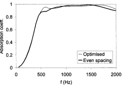
Figure 9 compares the new design methodology to the optimized depths previously presented. The depth sequence is given in Table I. As expected, the optimizer does slightly better, but the simplified design procedure produces high ab-sorption from less effort.
VII. CONCLUSIONS
[image:7.612.67.284.33.176.2]The above study has shown the usefulness of perforated sheets in the wells to achieve a more wide band absorption from a profiled construction. The optimized constant depth concept employing perforated plate can produce better ab-sorption than the ordinary absorber with perforated plate fixed at the top of the cavity. However, the frequency band is still narrow. The new optimized structure combined variable
FIG. 8. Performance of four different absorbers without perforations. The vertical lines indicate the location of the well resonances for the even spac-ing design.
depth sequence and perforated plates extends the absorption to lower frequencies as well maintaining good mid frequency absorption, and hence becomes a considerably better wide band absorber. In addition, a design procedure, which is more straightforward than numerical optimization, was out-lined and shown to give high absorption designs.
Incidentally, this new design also does better than more traditional Helmholtz designs, where the perforated sheet and resistive material are at the well entrance. Optimizations were carried out on a series of different Helmholtz absorbers stacked next to each other, but the new design was better. The extra degrees of freedom offered by having a variably positioned perforated sheet in the well seems to be a key ingredient to the good broad band absorption, and the mass
term in the traditional Helmholtz design causes problems in achieving broad band absorption as the mass term narrows the resonances. Consequently, an improved absorption struc-ture has been produced and validated.
ACKNOWLEDGMENTS
This work was funded by the Engineering and Physical Sciences Research Council共EPSRC兲of Britain, under Grant No. GR/L34396.
1
P. D’Antonio and T. J. Cox, ‘‘Diffusor application in rooms,’’ Appl. Acoust. 60, 113–143共2000兲.
2K. Fujiwara and T. Miyajima, ‘‘Absorption characteristics of a practically
constructed Schroeder diffuser of quadratic-residue type,’’ Appl. Acoust.
35, 149–152共1992兲.
3H. Kuttruff, ‘‘Sound absorption by preudostochastic diffusers共Schroeder
diffusers兲,’’ Appl. Acoust. 42, 215–231共1994兲.
4F. P. Mechel, ‘‘The wide-angle diffuser—A wide-angle absorber?,’’
Acus-tica 81, 379– 401共1995兲.
5
K. Fujiwara and T. Miyajima, ‘‘A study of the sound absorption of a quadratic-residue type diffuser,’’ Acustica 81, 370–378共1995兲.
6T. Wu, T. J. Cox, and Y. W. Lam, ‘‘From a profiled diffuser to an
opti-mised absorber,’’ J. Acoust. Soc. Am. 108, 643– 650共2000兲.
7
K. Fujiwara, K. Nakai, and H. Torihara, ‘‘Visualisation of the sound field around a Schroerer diffuser,’’ Appl. Acoust. 60, 225–236共2000兲.
8A. W. Guess, ‘‘Result of impedance tube measurements on the acoustic
resistance and reactance,’’ J. Sound Vib. 40, 119–137共1975兲.
9P. M. Morse and K. Ingard, Theoretical Acoustics 共McGraw-Hill, New
York, 1968兲, Chap. 6, pp. 285–291.
10W. H. Press et al., Numerical Recipes共Cambridge University Press,
Cam-bridge, 1989兲, Chap. 10, pp. 289–293.
11T. J. Cox, ‘‘Optimization of profiled diffusers,’’ J. Acoust. Soc. Am. 97,
[image:8.612.74.280.30.172.2]2928 –2941共1995兲.