Effects of Nozzle Shape on the Flow Characteristics of Premix Injector
Using Computational Fluid Dynamics (CFD)
RONNY Yii Shi Chin
1,a, SHAHRIN Hisham Amirnordin
1, AMIR Khalid
1,b1Combustion Research Group (CRG), Center for Energy and Industrial Environment Studies
(CEIES), Universiti Tun Hussein Onn Malaysia, 86400 Parit Raja, Batu Pahat, Johor, Malaysia
a
[email protected], [email protected]
Keywords: Eulerian multiphase flow, nozzle shapes, nozzle flow, flowcharacteristics, premix injector, cavitation
Abstract. The burner system is a patented, unique, higher-efficiency and fuel-injector system that works with a specially designed oil burner to create ultra-efficient combustion that reduces oil use, greenhouse gases and other harmful emissions. This research shows the injector nozzle geometries play a significant role in flow characteristics, atomization and formation of fuel-air mixture in order to improve combustion performance, and reducesome pollutant products from burner system. The aim of this research is to determine the effects of nozzle hole shape on flowcharacteristics of the premix injector by using CFD. Multiphase of volume of fluid (VOF) cavitating flow inside nozzles are determined by means of steady simulations and Eulerian-Eulerian two-fluid approach is used for performing mixing of Jatropha oil and air. Nozzle flow simulations resulted that cavitation area is strongly dependent on the nozzle hole shape. Conical hole with k-factor of 2 provides higher flow velocity and turbulent kinetic energy compared with conical hole with k-factor of 1.3 and cylindrical hole. The results show that the premix injector nozzle hole shape gives impact to the flowcharacteristics and indirectly affects the emission of the burner system.
Introduction
Global warming is a famous issue and also a major concern around the world. The reduction of harmful gases and improvement of burner system need to be a growing priority. The burner system is a patented, unique, higher-efficiency and fuel-injector system creates the ultra-efficient combustion that reduces oil use, greenhouse gases and other harmful emissions. In particular, mixture formation of biodiesel during early stage of burning is important process because ignition is controlled by physical process caused by multi-hole injection, air motion, chemical process of fuel decomposition and oxidation [1-2]. Besides, premix injector nozzle geometries in the burner system play a significant role in flow characteristics, atomization and formation of fuel-air mixture in order to improve combustion performance, and reduce some pollutant products [3-5]. Nozzle geometry of
the injector has been studied experimentally and numerically. Benajeset al.[2] analyzed
experimentally about the effects of conical and cylindrical nozzle orifices to the injection rate behavior of a common-rail fuel injection system with maximum needle lift on a cavitation test. Han
Methodology
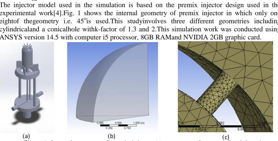
The injector model used in the simulation is based on the premix injector design used in the experimental work[4].Fig. 1 shows the internal geometry of premix injector in which only one
eightof thegeometry i.e. 45ois used.This studyinvolves three different geometries including
cylindricaland a conicalhole withk-factor of 1.3 and 2.This simulation work was conducted using ANSYS version 14.5 with computer i5 processor, 8GB RAMand NVIDIA 2GB graphic card.
The Governing equations
The following are the equations in conservation form for mass, momentum and energy which are used in the simulation.
Mass equation
dxdydz t dxdydz z w y v x u
(1)
Momentum equation
c f z w z z v y w y x w z u x z p z w y vw x uw t w b f z v y w z y v y y u x v x y p z vw y v x uv t v a f x w z u z y u x v y x u x x p z uw y uv x u t u z y x ... 2 V ... 2 V ... 2 V 2 2 2 (2) Energy equation
dxdydz z w y w x w z wp dxdydz z v y v x v y vp dxdydz z u y u x u x up C zz yz xz zy yy xy zx yx xx
dxdydz dxdydz z w y w x w z v y v x v z u y u x u z wp y vp x up zz yz xz zy yy xy zx yx xx V f (3)𝐾𝑓𝑎𝑐𝑡𝑜𝑟 = 𝐷𝑖𝑛− 𝐷𝑜𝑢𝑡
10 (4)
[image:2.595.58.534.83.324.2](a) (b) (c)
The conicity of the nozzle geometry is classified based on the inlet diameter of nozzle, Din, outlet
diameter, Dout and Kfactor, where Kfactor isconicity of the nozzle hole, Din isthe inlet diameter of the
nozzle in unit μm and Dout: is the outlet diameter of the nozzle in unit μm.
Boundary conditions for nozzle flow simulation. A steady multiphase simulation using Eulerian volume of fluid model was used in this work. The solid wall of the model was the basic boundary conditions that exist in the domain of fluid flow. Thesurface of injector was considered as stationary wall. Besides, the shear condition of the wall isspecified shear to create friction for the fluid flow. Periodic boundary conditions are applied to the left and right sides of the injector and spray chamber wall. Inlet was selected as mass flow rate inlet.Once the mass flow rate enters the domain, the velocity of the fluid, pressure, or mass flow rate can be known. Furthermore, this case consists of two different mass flow rates for Jatropha oil and air. The pressure output at 1 baratmospheric pressurewas set at the surface parallel to the surface of nozzle exit and bottom of the spray chamber.Moreover,the boundary conditions for three different nozzle geometries cases weresimilar throughout whole simulation process.
Results and discussion
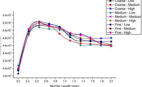
[image:3.595.177.422.476.625.2]Grid independence study.The numerical result from nozzle flow calculation is tested by using grid independence study. This work is focused on the effects of flow along the cylindrical and conical injector nozzles. It is reported that grid size has a significant effect on the convergence and predicted results [5, 6]. Grid sensitivity is tested on the model with different grid sizes as shown in Fig. 2. The number is ranged from 24997 to 114555 elements which are directly proportional to the numbers of nodes by ascending the level of grid sizes from coarse to fine. The average values are calculated and required to compare with the original velocities for each set of different grids in order to obtain the percentage of errors between the simulated velocities and the average velocities. The most preferable grid is selected by obtaining the best fit of percentage differences to the average velocities. Therefore, medium mesh level with high smoothing is chosen which representing the mesh density of 47662 due to its overall errors are the lowest compared to others grid level. This meshing scheme is selected to be used in further simulations.
0.0 0.2 0.4 0.6 0.8 1.0 1.2 1.4 1.6 1.8 2.0 3.8x10⁴
4.0x10⁴
4.2x10⁴
4.4x10⁴
4.6x10⁴
4.8x10⁴
5.0x10⁴
5.2x10⁴
5.4x10⁴
Ve
lo
ci
ty
(m/
s)
Nozzle Length (mm)
Coarse - Low Coarse - Medium Coarse - High Medium - Low Medium - Medium Medium - High Fine - Low Fine - Medium Fine - High
Figure 2: Velocity inside the nozzle against the nozzle length with different mesh density
(c) (d)
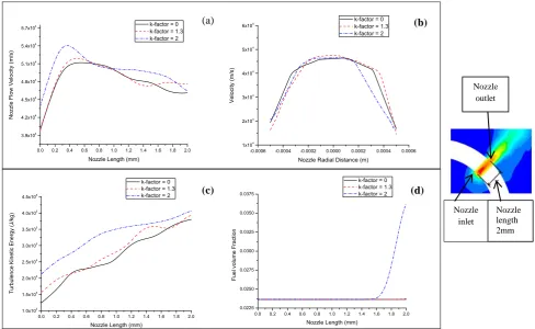
[image:4.595.67.533.109.212.2]represent the highest velocity at nozzle outlet compared to another two nozzle holes. Meanwhile, cylindrical nozzle generated less sharp shape of velocity graph at the outlet since its velocity is lowest.
Figure 3: Contour of mixture velocity in the nozzle for three different nozzles (a) cylindrical nozzle (b) konical hole k = 1.3 (c) konical hole k = 2.0
From the Fig. 4(c), it is obvious that the conical nozzle with k-factor of 2 flows inside the nozzle hole has the highest turbulence kinetic energy. Therefore, the conical nozzle with k-factor of 2 is more capable to reduce the cavitation inside the nozzle. Implosions of cavitation bubbles inside the nozzle holes increase when the turbulence kinetic energy increases. Besides, implode of cavitation bubbles contribute to the further break-up of the spray and it could leads to finer droplets of fuel which can fasten the process of evaporation of fuel. On the other hand, volume fraction of fuel increases in the nozzle hole when the k-factor of nozzle increased from zero to two. The fuel volume fraction for the conical nozzle (k-factor = 2) raises steadily at the area closer to the nozzle outlet as shown in the Fig. 3(d). This situation can be assumed that the fuel injection rate and total fuel injected increases.
0.0 0.2 0.4 0.6 0.8 1.0 1.2 1.4 1.6 1.8 2.0 3.9x10⁴
4.2x10⁴
4.5x10⁴
4.8x10⁴
5.1x10⁴
5.4x10⁴
5.7x10⁴
N
o
zzl
e
F
lo
w
Ve
lo
ci
ty
(m/
s)
Nozzle Length (mm)
k-factor = 0 k-factor = 1.3 k-factor = 2
-0.0006 -0.0004 -0.0002 0.0000 0.0002 0.0004 0.0006 1x10⁴
2x10⁴
3x10⁴
4x10⁴
5x10⁴
6x10⁴
Ve
lo
ci
ty
(m/
s)
Nozzle Radial Distance (m) k-factor = 0 k-factor = 1.3 k-factor = 2
0.0 0.2 0.4 0.6 0.8 1.0 1.2 1.4 1.6 1.8 2.0 1.0x10⁵
1.5x10⁵
2.0x10⁵
2.5x10⁵
3.0x10⁵
3.5x10⁵
4.0x10⁵
4.5x10⁵
T
urb
ul
en
ce
Ki
ne
tic
En
erg
y
(J/
kg
)
Nozzle Length (mm) k-factor = 0 k-factor = 1.3 k-factor = 2
0.0 0.2 0.4 0.6 0.8 1.0 1.2 1.4 1.6 1.8 2.0 0.0225
0.0250 0.0275 0.0300 0.0325 0.0350 0.0375
F
ue
l vo
lu
me
F
ra
ct
io
n
Nozzle Length (mm) k-factor = 0 k-factor = 1.3 k-factor = 2
Figure 4: Nozzle flow integral quantities. (a) Velocity, (b) radial velocity at nozzle outlet, (c) turbulence kinetic energy, (d) fuel volume fraction.
Conclusion
The analysis shows that thenozzle shapesstrongly influencethe flow properties inside nozzle orifice. Furthermore, it can be predicted that the spray injected from the nozzle outlet arealso affected by
(b)
(a)
Nozzle length 2mm Nozzle
outlet
Nozzle inlet
(c) (d)
[image:4.595.55.544.403.703.2]the nozzle flow characteristics. It is possible to believe that the concurrent phenomena are taken into account of few investigations. Cavitation also strongly reduced as the conicity of nozzle increase from k-factor of 0 to k-factor of 2. Therefore, the flow velocity at cavitating area and turbulence kinetic energy in the nozzle orifice rises from cylindrical nozzle to conical nozzle (k-factor =2). Besides, the increasing conicity of nozzle (k-(k-factor = 0 to k-(k-factor = 2) also encourage the fuel-air mixing in the nozzle and rate of fuel injection by increasing fuel volume fraction.
Acknowledgement
The authors also would like to thank the Ministry of Higher Education Malaysia for supportingthis research under the Exploratory Research Grant Scheme (ERGS) vot.E032.
References
[1] Amir Khalid, M.D. Anuar, Yusri Ishak, B. Manshoor, Azwan Sapit, Mutalib Leman, Izzuddin
Zaman, Emissions characteristics of small diesel engine fuelled by waste cooking oil, MATEC Web of Conferences, Volume 13, 2014, Article number 06006,
DOI: 10.1051/matecconf/20141306006.
[2] Amir Khalid, Keisuke Hayashi, Yoshiyuki Kidoguchi , Tomoaki Yatsufusa, Effect of air
entrainment and oxygen concentration on endothermic and heat recovery process of diesel ignition, (2011) SAE Technical Papers, DOI: 10.4271/2011-01-1834.
[3] T.N. Tuan, H.Okada, T. Tsukamoto, K. Ohe and K. Iwasawa, Effect of rounding-off nozzle hole
inlet on fuel injection and combustion characteristics under high-temperature and high-pressure, Translated from Journal of the JIME, 2007. Vol.42, No.2(Original Japanese).
[4] Amir Khalid, Norazwan Azman, Hanis Zakaria, B. Manshoor, Izzuddin Zaman, Azwan Sapit,
Mutalib Leman, Effects of storage duration on biodiesel properties derived from waste cooking
oil, Applied Mechanics and Materials, Volume 554, 2014, Pages 494-499,
DOI: 10.4028/www.scientific.net/AMM.554.494.
[5] Amir Khalid, N.Tamaldin, M. Jaat, M. F. M. Ali, B. Manshoor, Izzuddin Zaman, Impacts of
biodiesel storage duration on fuel properties and emissions, Procedia Engineering, volume 68, 2013, Pages 225 – 230, Elsevier, 2013, DOI: 10.1016/j.proeng.2013.12.172.
[6] J Benajes, JV Pastor, R Payri, AH Plazas, Analysis of the influence of diesel nozzle geometry in
the injection rate characteristics. Journal of Fluids Eng, 2004(126): p. 63–71.
[7] J.S. Han, L.P. Hsui, X.B Xie ,M.C. Lai N.A.Henein , Investigation of diesel spray primary
breakup and development for different nozzle geometries., SAE Paper No. 2002-01-2775, 2002.
[8] Michele Battistoni, C.N.G., Numerical analysis of injector flow and spray characteristics from
diesel injectors using fossil and biodiesel fuels. Applied Energy 97 (2012), December 2011. 656–666.
[9] Tingwen Li, A.G., Sreekanth Pannala, Mehrdad Shahnama, Madhava Syamlal, CFD
simulations of circulating fluidized bed risers, part I: Grid study. Powder Technology 254, 2014: p. 170–180.
[10] P. Worth Longest∗, S.V., Effects of mesh style and grid convergence on particle deposition
in bifurcating airway models with comparisons to experimental data. Medical Engineering & Physics 29 (2007), 2006: p. 350–366.
[11] Baumgarten., C., Mixture Formation in Internal Combustion Engines (2006), Germany:
Springer-Verlag Berlin Heidelberg.
[12] Chou, B.M.W.Y.a.S., Cavitation in injector nozzle holes- A parametric study. Engineering
Applications of Computational Fluid Mechanics, 2014. Vol. 8(No.1): p. 70-81.
[13] MF Sies, N Mustaffa, H Zakaria, H.Salleh, B. Manshoor, A. Khalid, A Review of the