International Journal of Emerging Technology and Advanced Engineering
Website: www.ijetae.com (ISSN 2250-2459,ISO 9001:2008 Certified Journal, Volume 3, Issue 4, April 2013)
415
Local Multipoint Distribution System
Jyoti Kshirsagar
1, Amruta Kachole
21Student, S.V.I.T., Chincholi, Nashik 2Lecturer, K.K.W. I.E.E.R. Nashik
Abstract— Local Multipoint Distribution System(LMDS), is a fixed wireless technology that operates in the 28 GHz band and offers line-of-sight coverage over distances up to 3-5 kilometers. It can deliver data and telephony services to 80,000 customers from a single node. Data transfer rates for LMDS can reach 1.5 Gbps to 2 Gbps, but a more realistic value may average around 38 Mbps (downstream). LMDS is a broadband wireless access technology governed by the IEEE and is outlined by the 802 LAN/MAN Standards Committee through the efforts of the IEEE 802.16.1 Task Group. The technology is also named as "WiBAS" (Wireless Broadband Access System).LMDS commonly operates on microwave frequencies across the 26 GHz and 29 GHz bands. In the United States, frequencies from 31.0 through 31.3 GHz are also considered LMDS frequencies. It is a point-to-multipoint specification utilizing microwave communications. Data-transport security is accomplished under LMDS by encrypting traffic flows between the broadband wireless modem and the WMTS (Wireless Modem Termination System) located in the base station of the provider’s network using Triple DES. LMDS uses approximately 1.3 GHz wide spectrum band at around 28 GHz. This provides a typical data rate for each LMDS channel of 1 Gbps. Because of the extremely high frequencies used, the transmitter must be located within 3 to 5 miles of the receiver. The limitation of short distance is that LMDS signals from one antenna will not interfere with other antennas placed 10 or more miles apart. This allows the radio bandwidth to be reused (frequency reused) in a cellular like fashion.
Keywords— Asynchronous Transfer Mode (ATM), Code-Division Multiple Access (CDMA), Customer Premises Equipment (CPE), Personal Communications Service (PCS), Quadrature Amplitude Modulation (QAM), Radio Frequency (RF), Synchronous Optical Network (SONET),Time-Division Multiple Access (TDMA).
I. INTRODUCTION
Local Multipoint Distribution Service (LMDS), is a broadband wireless point to multipoint communication system that provides reliable digital two-way voice, data and Internet services. The term "Local" indicates that the signals range limit.
"Multipoint" indicates a broadcast signal from the subscribers, the term "distribution" defines the wide range of data that can be transmitted, data ranging anywhere from voice, or video to Internet and video traffic(Later on in the 3rd section, the emergence of LMDS shows why it is good at transmitting such a wide variety of data). It provides high capacity point to multipoint data access that is less investment intensive. LMDS with its wireless delivery combined with a significant amount of spectrum allocated, promises to allow for a very high quality communication services. It transmits wave signals with-in small cells. As it has been tested by the US military and the corporate pioneers like the Speed Us, it is undoubtedly a proven technology. Originally designed for wireless digital television transmission LMDS and MMDS(Microwave Multipoint Distribution System) were predicted to serve the wireless Subscription Television needs. MMDS is also a broadband wireless communication service which operates at lower frequencies. Usually, LMDS operates at frequencies above the 10 Ghz range and MMDS at frequencies below the 10GHz range. Later on they were extended to offer other interactive services.
This technology is also named as "WiBAS" (Wireless Broadband Access System) Throughput capacity and reliable distance of the link depends on common radio link constraints and the modulation method used - either phase-shift keying or amplitude modulation. This paper performance evaluation studies of the effect of using different multiple access schemes in conjunction with different duplex schemes in the LMDS system architecture. Specifically, we examine frequency and time division multiple access, and frequency and time division duplex. LMDS commonly operates on microwave frequencies across the 26GHz and 29GHz bands. In the United States, frequencies from 31.0 through 31.3 GHz are also considered LMDS frequencies. The acronym LMDS is derived from the following:
International Journal of Emerging Technology and Advanced Engineering
Website: www.ijetae.com (ISSN 2250-2459,ISO 9001:2008 Certified Journal, Volume 3, Issue 4, April 2013)
416 M (Multipoint) indicates that the broadcast signals are
available to multiple users, i.e., signal is shared by multiple subscribers; the wireless return path, from subscriber to the base station, is a direct point-to-point transmission
D (Distribution) refers to the distribution of signals, which may consist of simultaneous voice, data, Internet, and video traffic to targeted subscribers S (System) implies the system provides the operator a
choice to serve any subscriber with the desired services that will be profitable today with adequate flexibility to grow and change based on evolving demands.
II. ADVANTAGE OF THE LMDS TECHNOLOGY
The biggest advantage of the LMDS technology is derived from its wireless nature: it gives operators an opportunity to provide consumers with access bandwidths and two-way capability without digging up streets. This one fact that no right-of-way clearances are required to deploy it makes it sufficiently enticing as a technology. LMDS has huge chunks of under-utilized spectrum ready to go, more than enough to satisfy pent-up demand for voice, private data networks, and high-speed Internet access.
Further, the technology is stable and all-digital, and assures effective delivery of high-quality services that are demanded by consumer and enterprise users. In addition, this advantage has provided today cellular operators across the globe an economical way to quickly deploy cell sites to provide next generation of bandwidth intensive data services, beyond the traditional voice service. This added benefit will certainly not be lost in India‘s competitive landscape with cellular and limited-mobility operators going head-to-head and where the fine line between fixed and cellular services blends into converged applications for the benefit of the consumer.
III. CONCEPT
LMDS is a broadband wireless point-to-multipoint communication system operating above 20 GHz (depending on country of licensing) that can be used to provide digital two-way voice, data, Internet, and video services (see Figure ).
[image:2.612.325.591.145.311.2]
Figure 3.1 LMDS System
IV. NEED OF LMDS
International Journal of Emerging Technology and Advanced Engineering
Website: www.ijetae.com (ISSN 2250-2459,ISO 9001:2008 Certified Journal, Volume 3, Issue 4, April 2013)
417 But local multipoint distribution systems (LMDS), a broadband wireless access technology, being aggressively promoted in India by companies like Hughes Network Systems (HNS), promises to be a panacea to most of these problems.
The technology has already found market acceptance in the West. Even countries in the Asia-Pacific region, such as Hong Kong and Singapore, have issued LMDS licenses to cellular operators and also basic service providers. India is not far behind in the race. Hughes Tele.com (now a part of Tata Teleservices) has already deployed LMDS in Mumbai and is looking at deploying the technology in other states where it has a presence. Tata Teleservices has deployed the technology in the Tamil Nadu circle. Essar Telecom has already entered into a deal with Motorola India to deploy the technology for offering ISP services in close to 52 cities in the country. HNS is in talks with telecom majors like MTNL, BSNL, Hutch and other service providers for offerings its solutions in all the metros and other cities with a high population density.
V. WHY DEPLOY LMDS? Operators must focus on profitability by:
Optimizing invested capital
Building multi-purpose platforms to capitalize on converging services rather than deploying single-purpose networks
Increasing the per subscriber revenues
LMDS can help achieve these goals:
Quick time to market: wireless means minimal planning, minimal a right of way issues, no need to predict demand, LMDS can be re-deployed
Converged services / more revenues: One platform, many applications means consolidation of different access technologies and hence lower overall cost for the operator
Expanded broadband service area: LMDS extends the fiber footprint 3-5 km to either side of the fiber, encompassing many more buildings which can be served with broadband services.
VI. LMDSTECHNICAL AND DESIGN ISSUES
A normal LMDS setup has a central facility with a fiber-linked PSTN and internet connections relay signal via point to point microwave links which in turn pass the signal along to hubs, located on rooftops or as stand-alone towers, for Point to Multipoint (PMP)transport to the end site.
Basically, four parts in the LMDS architecture are 1. Network operations center(NOC)
2. Fiber based infrastructure 3. Base station
4. Customer Premise Equipment and NOC designs.
The network management equipment for managing regions of customer network comes under the NOC. Multiple NOC can be interconnected. The fiber based infrastructure basically consists of SONET OC-12 OC-3 and DS-3 links, the ATM and IP switching systems, Interconnections with the PSTN, the central office equipment. The conversion from fibered infrastructure to a wireless infrastructure happens at the base stations. Interface for fiber termination, modulation and demodulation functions, microwave transmission and reception equipment are a part of the base station equipment. Local switching can also be present in the base station. If local switching is present then customers communicating in the same base station can communicate with each other without entering the fiber infrastructure. The customer premise equipment varies widely from vendor to vendor. All configurations include in door digital equipment include modulation and outdoor mounted microwave equipment. The customer premise equipment may attach to network using TDMA, FDMA or CDMA. Different customer premise equipment require different configurations. The customer premise will run the full range from DS0, POTS, 10BaseT,Unstructured DS1 structured DS1 Frame Relay, ATM25 serial ATM over T1, DS-3, OC-3 and OC-1. And the customer premise locations can range anywhere from malls to residential locations.
VII. NETWORK ARCHITECTURE
International Journal of Emerging Technology and Advanced Engineering
Website: www.ijetae.com (ISSN 2250-2459,ISO 9001:2008 Certified Journal, Volume 3, Issue 4, April 2013)
418 VIII. SYSTEM EQUIPMENT SEGMENTS
The NOC contains the network management system (NMS) equipment that manages large regions of the customer network. Multiple NOCs can be interconnected. The fiber-based infrastructure typically consists of synchronous optical network (SONET) optical carrier (OC)–12, OC–3, and DS–3 links; central-office (CO) equipment; ATM and IP switching systems; and interconnections with the Internet and public switched telephone networks (PSTNs).
The base station is where the conversion from fibered infrastructure to wireless infrastructure occurs. Base-station equipment includes the network interface for fiber termination; modulation and demodulation functions; and microwave transmission and reception equipment typically located atop a roof or a pole. Key functionalities which may not be present in different designs include local switching. If local switching is present, customers connected to the base station can communicate with one another without entering the fiber infrastructure. This function implies that billing, channel access management, registration, and authentication occur locally within the base station.
The alternative base-station architecture simply provides connection to the fiber infrastructure. This forces all traffic to terminate in ATM switches or CO equipment somewhere in the fiber infrastructure. In this scenario, if two customers connected to the same base station wish to communicate with each other, they do so at a centralized location. Billing, authentication, registration, and traffic-management functions are performed centrally.
The customer-premises configurations vary widely from vendor to vendor. Primarily, all configurations will include outdoor-mounted microwave equipment and indoor digital equipment providing modulation, demodulation, control, and customer-premises interface functionality. The CPE may attach to the network using time-division multiple access (TDMA), frequency-division multiple access (FDMA), or code-division multiple access (CDMA) methodologies. The customer premises interfaces will run the full range from digital signal, level 0 (DS–0), plain old
telephone service (POTS), 10BaseT, unstructured DS–1, structured DS–1, frame relay, ATM25, serial ATM over T1, DS–3, OC–3, and OC–1. The customer premises locations will range from large enterprises (e.g., office buildings, hospitals, campuses), in which the microwave equipment is shared between many users, to mall locations and residences, in which single offices requiring 10BaseT and/or two POTS lines will be connected.
Obviously, different customer-premises locations require different equipment configurations and different price points.
IX. ARCHITECTURAL OPTIONS
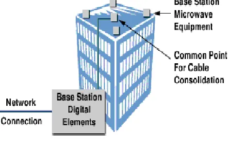
[image:4.612.328.564.277.425.2]LMDS system operators offer different services and have different legacy systems, financial partners, and business strategies. As a result, the system architecture used will differ between all system operators. The most common architectural type uses co-sited, base-station equipment.
Figure 9.1 Co-Sited Base Stations
The indoor digital equipment connects to the network infrastructure, and the outdoor microwave equipment mounted on the rooftop is housed at the same location (see Figure 9.1). Typically, the radio frequency (RF) planning for these networks uses multiple sector microwave systems, in which transmit- and receive-sector antennas provide service over a 90-, 45-, 30-, 22.5-, or 15-degree beam width. The idealized circular coverage area around the cell site is divided into 4, 8, 12, 16, or 24 sectors.
International Journal of Emerging Technology and Advanced Engineering
Website: www.ijetae.com (ISSN 2250-2459,ISO 9001:2008 Certified Journal, Volume 3, Issue 4, April 2013)
[image:5.612.51.286.115.308.2]419
Figure 9.2 Analog Fiber Architecture
X. MODULATION
Modulation methods for broadband wireless LMDS systems are generally separated into phase shift keying (PSK) and amplitude modulation (AM) approaches. The modulation options for TDMA and FDMA access methods are almost the same.
The TDMA link modulation methods typically do not include the 64–quadrature amplitude modulation (QAM), although this might become available in the future. The FDMA access modulation methods are listed in
Table 2 and are rated on an estimated scale as to the amount of bandwidth they require for a 2–Mbps constant bit rate (CBR) connection (without accounting for overhead due to ATM and FEC). Values are approximate, as there are issues involving channel filter mask roll-off factors, which can be important when providing the relationship between microwave bandwidth and data rates.
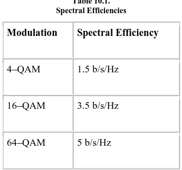
Table 10.1. Spectral Efficiencies
Modulation Spectral Efficiency
4–QAM 1.5 b/s/Hz
16–QAM 3.5 b/s/Hz
64–QAM 5 b/s/Hz
XI. NETWORK MANAGEMENT
LMDS network management is designed to meet a network operator's business objectives by providing highly reliable network management services. Network management requires the following:
Fault Management
This is necessary to identify, localize, and correct errors or faults in the network. Each device within a wireless network should be monitored for troubleshooting or performance. All LMDS devices collect and report statistics pertaining to traffic throughput, boundary condition violations, and management activities.
Configuration Management
This is necessary in order to provision, inventory, initialize, and back-up network resources. The LMDS equipment should be auto-discovered when new equipment is added to a node. This minimizes the amount of provisioning needed to install or upgrade equipment.
Accounting Management
This is necessary to collect and process billing information. Each manageable node in the wireless portion of the network should maintain a collection of statistics that can be accessed by a third-party billing system as input. Users should be identified on a per-network user basis.
Performance Management
This is necessary to collect, filter, and analyze network resource statistics. There are a number of parameters that should be monitored and configured on each network node, from T1 traffic throughput to output power level. The management station should monitor these parameters and adjust them to increase performance.
Security Management
[image:5.612.78.258.545.713.2]International Journal of Emerging Technology and Advanced Engineering
Website: www.ijetae.com (ISSN 2250-2459,ISO 9001:2008 Certified Journal, Volume 3, Issue 4, April 2013)
420 XII. CONCLUSION
LMDS promises a wireless alternative to fiber and coaxial cables. It has the potential to replace the existing wired networks, it may prove to be the easiest way to deliver high speed data and two way video service. Its capability of handling thousands of voice channels with the existing bandwidth makes it a good contestant in the voice industry. With current industry trends, that are tending to merge the telecommunication and the networking industries, LMDS seems to be a solution that suits all their needs. For the recent digital TV world, LMDS is a very good choice considering the fact that LMDS was designed with Digital TV broadcast in mind.
Breakthroughs in radio technology, along with increased industry confidence following the success of personal communications service (PCS) and cellular mobile services have dramatically improved confidence in radio as a reliable local access technology. LMDS, as a technology is mature and reliable and delivers compelling advantages for adoption in the world.
REFERENCES
[1] Langston, J.L., ―Local Multipoint Distribution Services (LMDS) System Concepts and Implementation,‖ IEEE Communications Magazine, July 1997, pp.12-15.
[2] Hikmet Sari, Broadband radio access to homes and businesses, IEEE Computer Networks Vol. 31 (1999) ,Pp 379-393.
[3] Stamatelos, G.M., ―Millimeter radio access to multimedia services via LMDS,‖ IEEE Communications Technical Journal, 1996.
[4] Douglas A.G., ―Optimal Hub deployment for 28GHz LMDS systems,‖ IEEE Wireless Communication Conference, May 1997, pp.1 8-22.
[5] Papazian, P. et al., ―Study of the Local Multipoint Distribution Service Radio Channel,‖ IEEE Transactions on Broadcasting, vol.43, no.2, June 1997.
[6] Correia, L.M., and Reis, J.J., ―Wideband Characterization of the Propagation Channel for outdoors at 60 GHz,‖ in Proc. PIMRC‘ 96,vol. 2.
[7] Cornaglia, B., Santaniello, R., Leonardi, E., Cigno, R.L., Meo, M., Neri, F., and Saracino, D., LMDS System: A possible solution for wireless ATM Access networks,‖ IEEE International Conference on ATM, 1998, pp.41-50.
[8] Devasirvatham, D.M.J., Murray, R.R., Wolter, D.R., ―Time Delay Spread Measurements in a Wireless Local Loop Testbed,‖ Proc. IEEE VTC ‗95 , Vol. 1, July 1995 .
[9] Dilworth, I.J., and L‘Ebraly, B., ―Propagation effects due to fo liage and building scatter at millimeter wavelengths,‖ in Ninth International Conference on Antennas and Propagation, vol. 2, pp. 51-53, April 1995.
[10] Donaldson, R.W. and A.S. Beasley, ―Wireless CATV network access for personal communications using simulcasting,‖ IEEE Transactions on Vehicular Technology, Volume 43, Issue 3, Part: 1-2, Aug. 1994. [11] Douglas A. Gray, ―A Broadband Wireless Access System at 28
GHz‖, Wireless Communications Conference , Proceedings, May 1997, pg.1-7.
[12] Durgin, G.D., Rapp port, T.S., and Xu, H., ―Measurements and Models for Radio Path Loss and Penetration Loss In and Around Homes and Trees at 5.85 GHz,‖ IEEE Transactions on, vol. 46, issue 11, Nov 1998. Communications
[13] Freeman, R.L., Telecommunication Transmission Handbook, Third Edition, John Wiley & Son s Inc., 1991.
[14] Izadpanah, H., Gregoire, D., Schaffner, J., and Hsu, H.P., ―MM-wave wireless access technology for the wideband wireless local loop applications,‖ IEEE Communications Magazine, Jan. 1998, pp. 5-7.