ISSN Online: 2161-4962 ISSN Print: 2161-4954
Experimental Study of Filling Ratio Effect on the
Thermal Performance in a Multi-Heat Pipe with
Graphene Oxide/Water Nanofluids
Mohamed Salem
1,2*, Tarek A. Meakhail
1, Magdy A. Bassily
3, Shuichi Torii
21Department of Mechanical Engineering, Faculty of Energy Engineering, Aswan University, Aswan, Egypt 2Graduate School of Science and Technology, Kumamoto University, Kumamoto, Japan
3Department of Mechanical Engineering, Faculty of Engineering, Minia University, Minia, Egypt
Abstract
This experimental study is performed to investigate heat transfer performance of a multi-heat pipe cooling device in the condition of different filling ratios (40%, 60%, 80% and 100%) and different constant heat fluxes (10 - 30 W). Here, pure water (dis-tilled water) and graphene oxide (GO)/water nanofluids are employed respectively as working fluid. GO/water nanofluids were synthesized by the modified Hummers method with 0.05%, 0.10%, 0.15%, and 0.20% volume concentrations. Multi-heat pipe is fabricated from copper; the heating and cooling sections are the same size and both are connected by four circular parallel tubes. Temperature fields and thermal resistance are measured for different filling ratio, heat fluxes and volume concentra-tions. The results indicated that the thermal performance of heat pipe increased with increasing the concentration of GO nanoparticles in the base fluid, while the maxi-mum heat transfer enhancement was observed at 0.20% volume concentration. GO/ water nanofluids showed lower thermal resistance compared to pure water; the op-timal thermal resistance was obtained at 100% filling charge ratio with 0.20% volume concentration. Studies were also demonstrated that heat transfer coefficient of the heat pipe significantly increases with increasing the input heat flux and GO nanopar-ticles concentration.
Keywords
Multi-Heat Pipe, Graphene Oxide, Filling Ratio, Volume Fraction, Thermal Resistance
1. Introduction
A multi-heat pipe is a device that transfers heat from the hot interface to the cold one
How to cite this paper: Salem, M., Meak-hail, T.A., Bassily, M.A. and Torii, S. (2016) Experimental Study of Filling Ratio Effect on the Thermal Performance in a Multi- Heat Pipe with Graphene Oxide/Water Na-nofluids. World Journal of Nano Science and Engineering, 6, 153-164.
http://dx.doi.org/10.4236/wjnse.2016.64014
Received: November 28, 2016 Accepted: December 18, 2016 Published: December 21, 2016
Copyright © 2016 by authors and Scientific Research Publishing Inc. This work is licensed under the Creative Commons Attribution International License (CC BY 4.0).
by phase change and convection of the working fluid. Vapor is generated at the heat source level (evaporator) and it condenses at the heat sink level (condenser). The liquid returns from the evaporator to the condenser through a capillary structure. Heat pipes have a variety of advantages, such as high heat removal rate per unit volume, a fully passive working principle, and easy applicability. Heat pipes have been used in various thermal engineering fields such as computer CPUs, solar energy collectors and micro device transmitting equipment.
a pulsating heat pipe using methanol and de-ionized (DI) water. They concluded that the minimum start-up power and thermal resistance were obtained at 50% and 40% filling ratio for DI water and methanol, respectively. Qu J. et al. [8] investigated expe-rimentally the performance of a stainless steel oscillating heat pipe (OHP) charged with base water and spherical Al2O3 particles of 56 nm in diameter. The effects of filling
ra-tios, mass fractions of alumina particles and power inputs on the total thermal resis-tance of the OHP were investigated. They showed that the maximum thermal resisresis-tance was decreased by 0.14˚C/W (or 32.5%) when the power input was 85.8 W at 70% filling ratio and 0.9% mass fraction. Lin Y. et al. [9] studied the effect of silver nanofluid (20 nm in diameter) on copper pulsating heat pipe thermal performance. The thermal per-formance was studied at different concentration (100 ppm and 450 ppm), various filled ratio (20% - 80% FR) and different heat power (5 W - 85 W). The results showed that the best filled ratio was 60% and the better working fluid was 100 ppm of silver nanof-luid. Khandekar S. et al.[10] investigated the effect of working fluid (water, ethanol and R-123) and filling ratio on the thermal performance of closed loop pulsating heat pipe in vertical and horizontal orientation. They found that the best performance was meas-ured at low filling ratio for all working fluids. Salem M. et al. [11] measured thermal conductivity of graphene oxide/water nanofluid with different volume concentration ranged from 0.05% to 0.2% using transient hot wire method (KD2 thermal property meter). They showed that the thermal conductivity was enhanced with reference to pure water. Also, it was increased by increasing nanoparticles concentration.
In the present work, experimental studies have been conducted on the thermal per-formance of a copper multi-heat pipe charged with pure water (distilled water) and graphene oxide (GO)/water nanofluids as working fluid. The experiment was performed at different volume concentrations (0.05, 0.10, 0.15 and 0.20 vol%), various filling charge ratios (40%, 60%, 80% and 100% FR) and different heat fluxes (10 W - 30 W).
2. Materials and Methods
2.1. Materials
Graphene oxide (GO)/water nanofluids were prepared by dispersing GO nanoparticles into pure water as a base fluid. GO nanoparticles were synthesized from natural gra-phite powder by a modified Hummers method [11] [12]. Graphite fine powders (45 μm) was purchased from Wako pure chemical industries (Japan), concentrated sulfuric acids (H2SO4), sodium nitrate (NaNO3), potassium permanganate (KMnO4), hydrogen
peroxide (30% H2O2), hydrochloric acid (5% HCl) and deionized water were used
throughout Hummers method. GO/water nanofluids with four different volume con-centrations at 0.05%, 0.10%, 0.15% and 0.20% were prepared for this experiment. The thermal conductivity and the viscosity of GO/water nanofluids were measured in our previous study [11].
2.2. Test Section
Figure 1. Multi-heat pipe with thermocouple locations (all dimensions are in mm).
and condenser. A multi-heat pipe was made of copper in laboratory of Kumamoto university-Japan. The external dimensions for heating and cooling sections are 45 × 45 × 8 mm, and the internal dimensions are 42 × 42 × 5 mm. The adiabatic section is con-sisted of four parallel circular tubes whose dimension is ϕ6 (external diameter) × ϕ5 (inlet diameter) × 45 mm (length). As shown in figure, twelve k-type thermocouples were installed on the test section, with five of them embedded in the evaporator section (H1, H2, H3, H4, and H5), four in the adiabatic section (a1, a2, a3, and a4), and three in the
condenser (C1, C2, and C3).
2.3. Experimental Setup and Procedures
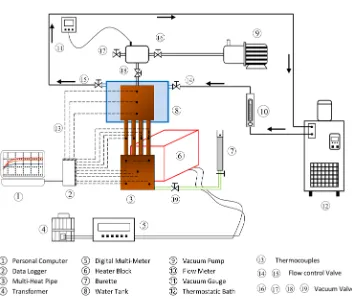
Figure 2. Schematic of experimental set-up.
immersing it into the plastic cooling chamber and water was used as the coolant fluid which pumped from the thermostatic bath (NCC-1100, Japan). The cooling water flow rate was measured by flow meter (KOFLOC, Japan). Both evaporator and adiabatic sec-tions were thermally insulated with glass fiber to prevent heat loss. The surface tem- peratures of the heat pipe were measured using twelve k-type thermocouples (Figure 1).
The test section was evacuated using the vacuum pump to remove the non-con- densable gases. Cooling water was then supplied from thermostatic bath to the cooling chamber at a volume flow rate of 1.5 l/min and 15˚C. The test section was then charged with the working fluid. The filling charge ratios (FR) (volume ratio of the working fluid to the internal volume of the evaporator section) were varied at 40%, 60%, 80% and 100% for each working fluid. The vacuum pressure inside the test section was set to 9.5 kPa for all cases. The test section was heated gradually until a steady state was attained.
3. Results and Discussion
3.1. Wall Temperature of Heat Pipe
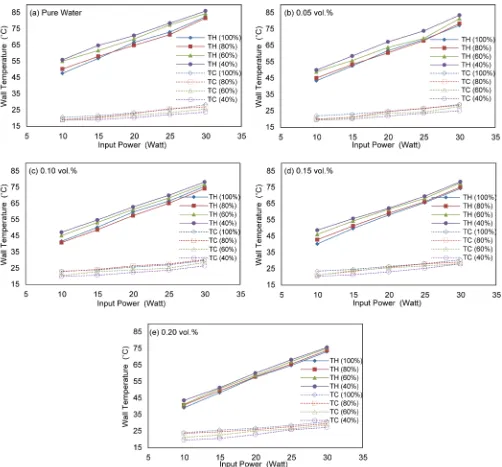
The evaporator and condenser wall temperature are therefore calculated as the arith-metic average of the thermocouples located in the evaporator and condenser sections. The mean temperature of evaporator and condenser sections are calculated and plotted against the heat load at different volume concentrations and filling ratios in Figure 3.
[image:6.595.48.550.218.685.2]The results indicate that an increase of heat flux leads to increase the evaporator and condenser wall temperature at different volume concentration and filling ratio. This is due to high heat flux causes an increase of the evaporation of working fluid leading to increase pressure in the heat pipe affecting higher saturation temperature of working
fluid in heat pipe. The wall temperature of the heat pipe reduces from evaporator to condenser section. Also, a rough comparison between pure water and GO/water na-nofluids shows that presence of GO nanoparticles significantly reduces the evaporator temperature and slightly increases the condenser temperature, which means that the thermal performance of the heat pipe greatly enhances, when GO nanoparticles are added into pure water.
Based on the experimental results, the mean wall temperature of evaporator reduced as the filling charge ratio increased for volume concentration 0.15% and 0.20% at the same input heat flux. For pure water (distilled water), 0.05% and 0.10% volume con-centration, evaporator temperature decreases with the rise of filling ratio till 80%, but it decreased when the filling ratio reached 100% for 0.10 vol% at different heat load and after 15 W for pure water and 0.05% volume concentration. The condenser tempera-ture increases in slow rate with increment of filling ratio. The highest condenser tem-perature is obtained at 100% filling ratio for pure water, 0.05, 0.15 and 0.20 vol% and at 80% for 0.10% volume concentration.
For 0.20% volume concentration, the rate of change of evaporator wall temperature with different filling ratio is very small because the viscosity is too high [11]. The max-imum percentage of temperature reduction in the evaporator section compared with pure water is obtained at 0.20% volume fraction (the temperature reduced by 17.82%, 18.76%, 25.24% and 22.10% for 100%, 80%, 60% and 40% filling ratio, respectively).
3.2. Thermal Resistance
The thermal performance of the multi-heat pipe can be characterized by the overall thermal resistance (Rth). The overall thermal resistance results from the combination of
both the condenser and evaporator thermal resistance, which defined as the ratio of the temperature difference to a given heat load:
H C th T T R Q −
= (1)
where TH is the mean evaporator wall temperature, TC is the mean wall temperature of
the condenser and Q is the input heat load.
Considering that the heat loss from the evaporator and adiabatic sections of the mul-ti-heat pipe to ambience was negligibly small due to good insulation, heating power input Q can be evaluated as follows:
Q= ×V I (2)
where V and I are the applied voltage and current, respectively.
Figure 4. Thermal resistances as a function of input heat load and filling ratio.
volume fraction. The lowest overall thermal resistance is obtained at 80% filling ratio for 0.10% volume concentration and at 100% for 0.15% and 0.20% volume concentra-tion at different heat load. For pure water and 0.05% volume concentraconcentra-tion, the lowest thermal resistance is obtained at 80% filling ratio when the heat load is higher than 15W. As compared with pure water, the maximal decrease of the thermal resistance was about 1.20˚C/W, 1.39˚C/W, 1.63˚C/W and 1.31˚C/W (or 44.45%, 44.82%, 44.98% and 35.27%, respectively) which occurred at 100%, 80%, 60% and 40% filling ratio, respec-tively, when the power input was 10 W for maximum volume concentration 0.20%. Thus, the addition of GO nanoparticles in the base fluid (pure water) enhanced the thermal resistance of the multi-heat pipe.
The GO/water nanofluids can enhances the thermal resistance with different reason: the presence of nanoparticles in base fluid increases the thermal conductivity of base fluid. Reason for enhancement of thermal conductivity is micro-conductive between solid and liquid molecules, Brownian motion of nanoparticles and clustering in nanof-luid.
3.3. Overall Heat Transfer Coefficient
The overall heat transfer coefficient (h) of the heat pipe calculated using the surface temperature of evaporator and condenser section using Equation (3).
(
)
e H C
Q h
A T T
=
− (3)
where Ae is the cross section area of the evaporator section.
Figure 5 shows the overall heat transfer coefficient against the heat load for all the filling charge ratios and the volume concentrations. For GO/water nanofluid, a higher heat transfer coefficient is registered for all volumetric concentrations of nanoparticles in comparison with those reported for pure water at a similar condition. The GO na-noparticles in the heat pipe not only increased the fluid thermal conductivity but also enhanced the heat transfer coefficient due to the particles migration. It is clear from
Figure 5 that the increase of the heat load improved the heat transfer coefficient of the heat pipe for each filling ratio.
Results demonstrated that the heat transfer coefficient of heat pipe drastically in-creases with increasing the filling charge ratio at the same input heat fluxes, because the temperature difference between the evaporator and condenser section decreases with increasing the filling charge ratio. The optimum heat transfer coefficient was obtained at 100% filling ratio for 0.15 vol.% and 0.20 vol.% and at 80% for 0.10% volume con-centration. For pure water and 0.05 vol.%, the heat transfer coefficient increases with the rise of filling ratio till 15 W input heat load. Beyond 15 W, the maximum heat transfer coefficient was obtained at 80% filling ratio.
4. Conclusion
Figure 5. Overall heat transfer coefficient as a function of input heat load and filling ratio.
different filling charge ratios (40%, 60%, 80% and 100%) and different volume concen-trations of graphene oxide/water nanofluids (0.05%, 0.10%, 0.15% and 0.20%) in vertic-al orientation. The main outcomes were resumed below:
1) The heat transfer performance of a multi-heat pipe was apparently improved after the addition of GO nanoparticles in the working fluid.
2) 0.20% was the optimal volume concentration of GO/water nanofluids to achieve the maximal heat transfer enhancement for the filling ratios 40%, 60%, 80% and 100%.
0.20% volume concentration.
4) With increasing the input heat power and volumetric concentration of nanofluid, the overall thermal resistance of the heat pipe was increased.
5) The optimal thermal resistance of a multi-heat pipe was obtained at 100% filling charge ratio for 0.20% volume concentration.
6) For all working fluids and filling ratios, the overall heat transfer coefficient of this multi-heat pipe increased by increasing the input heat power.
7) For all filling ratios, the overall heat transfer coefficient improved with increasing the volumetric concentration of GO/water nanofluids.
8) The overall heat transfer coefficient depended greatly on the filling ratio, and the lower filling ratio (40%) led to smaller heat transfer coefficient.
Acknowledgements
The first author would like to acknowledge the Cultural Affairs and Missions Sector, Ministry of Higher education, Egypt, for providing the financial support (PhD scholar-ship) for this research and the extended help of Thermal engineering laboratory under the Department of Mechanical System Engineering, Kumamoto University, Japan, for providing the facility for experimentation
References
[1] Kim, K. and Bang, I. (2016) Comparison of Flooding Limit and Thermal Performance of Annular and Concentric Thermosyphons at Different Fill Ratios. Applied Thermal Engi-neering, 99, 179-188. https://doi.org/10.1016/j.applthermaleng.2015.12.137
[2] Sarafraz, M. and Hormozi, F. (2014) Experimental Study on the Thermal Performance and Efficiency of a Copper Made Thermosyphon Heat Pipe Charged with Alumina-Glycol Based Nanofluids. Powder Technology, 266, 378-387.
https://doi.org/10.1016/j.powtec.2014.06.053
[3] Lips, S., Lefèvre, F. and Bonjour, J. (2010) Combined Effects of the Filling Ratio and the Vapour Space Thickness on the Performance of a Flat Plate Heat Pipe. International Jour-nal of Heat and Mass Transfer, 53, 694-702.
https://doi.org/10.1016/j.ijheatmasstransfer.2009.10.022
[4] Mameli, M., Manno, V., Filippeschi, S. and Marengo, M. (2014) Thermal Instability of a Closed Loop Pulsating Heat Pipe: Combined Effect of Orientation and Filling Ratio. Expe-rimental Thermal and Fluid Science, 59, 222-229.
https://doi.org/10.1016/j.expthermflusci.2014.04.009
[5] Barua, H., Ali, M., Nuruzzaman, M., Islam, M. and Feroz, C. (2013) Effect of Filling Ratio on Heat Transfer Characteristics and Performance of a Closed Loop Pulsating Heat Pipe. 5th BSME International Conference on Thermal Engineering, 56, 88-95.
https://doi.org/10.1016/j.proeng.2013.03.093
[6] Pote, A. and Pachghere, P.R. (2015) Experimental Analysis on Thermal Performance of Closed Loop Pulsating Heat Pipe Using ZnO/Water Nanofluid. International Journal of Science and Research, 4, 235-239. https://www.ijsr.net/archive/v4i5/v4i5.php
[8] Qu, J., Wu, H. and Cheng, P. (2010) Thermal Performance of an Oscillating Heat Pipe with Al2O3-Water Nanofluids. International Communications in Heat and Mass Transfer, 37,
111-115. https://doi.org/10.1016/j.icheatmasstransfer.2009.10.001
[9] Lin, Y., Kang, S. and Chen, H. (2008) Effect of Silver Nano-Fluid on Pulsating Heat Pipe Thermal Performance. Applied Thermal Engineering, 28, 1312-1317.
https://doi.org/10.1016/j.applthermaleng.2007.10.019
[10] Khandekar, S., Dollinger, N. and Groll, M. (2003) Understanding Operational Regimes of Closed Loop Pulsating Heat Pipes: An Experimental Study. Applied Thermal Engineering, 23, 707-719. https://doi.org/10.1016/S1359-4311(02)00237-5
[11] Salem, M., Bassily, M., Meakhail, T. and Torii, S. (2016) Experimental Investigation on Heat Transfer and Pressure Drop Characteristics of Graphene Oxide/Water Nanofluid in a Circular Tube. International Journal of Mechanical Engineering, 4, 12-22.
http://ipasj.org/issue1.php?vol=Volume4Issue3&Jname=4
[12] Hummers, W. Jr. and Offeman, R. (1958) Preparation of Graphitic Oxide. Journal of the American Chemical Society, 80, 1339. https://doi.org/10.1021/ja01539a017
Submit or recommend next manuscript to SCIRP and we will provide best service for you:
Accepting pre-submission inquiries through Email, Facebook, LinkedIn, Twitter, etc. A wide selection of journals (inclusive of 9 subjects, more than 200 journals)
Providing 24-hour high-quality service User-friendly online submission system Fair and swift peer-review system
Efficient typesetting and proofreading procedure
Display of the result of downloads and visits, as well as the number of cited articles Maximum dissemination of your research work
Submit your manuscript at: http://papersubmission.scirp.org/