http://www.scirp.org/journal/jemaa ISSN Online: 1942-0749
ISSN Print: 1942-0730
Electromagnetic Modulation of Dipole
Antenna inside an Infinite Rectangular
Waveguide Using MoM-GEC
Hafawa Messaoudi, Aidi Mourad, Taoufik Aguili
Communication System Laboratory Sys’Com, National Engineering School of Tunis, University of Tunis El Manar, Tunis, Tunisia
Abstract
A theoretical and modulation study of a dipole antenna located in rectangular wave-guide is presented. The aim is to determine the nature and dimensions which allow us to attain the simulations in free space. We compare the behavior of a dipole an-tenna modeled by MOM-GEC with those obtained in free space. A method of mo-ment (MoM) approach combined to the generalized equivalent circuit (GEC) mod-eling is applied to compute the input impedance of a dipole antenna resonating at 1.8 GHz. A parametric study is conducted to investigate the wall effects on the antenna performances. Also we study the convergence of the input impedance as a function of test function number. The current values with integral method (MOM) are pared with the computed values obtained from numerical methods such as the com-bined MOM-GEC. The simulated values agree with values obtained from numerical methods.
Keywords
MOM-GEC, Infinite Waveguide, Dipole Antenna
1. Introduction
Various types of electromagnetic source were used to model an antenna for mobile phone applications. A dipole antenna is the simplest and most widely used. The dipole antenna was modeled as perfect conductor with feeding gap at center between two arms. We consider a thin dipole antenna of “L” length being fed at its center.
A new formulation based on the integral-equation formulation in the frequency do-main is used to study the behavior of a dipole antenna with finite length. The MoM method, designed and carefully optimized, can be a highly efficient and reliable tool for How to cite this paper: Messaoudi, H.,
Mourad, A. and Aguili, T. (2016) Electro-magnetic Modulation of Dipole Antenna inside an Infinite Rectangular Waveguide Using MoM-GEC. Journal of Electromag-netic Analysis and Applications, 8, 161-172. http://dx.doi.org/10.4236/jemaa.2016.89016
Received: July 19, 2016 Accepted: August 30, 2016 Published: September 2, 2016
Copyright © 2016 by authors and Scientific Research Publishing Inc. This work is licensed under the Creative Commons Attribution International License (CC BY 4.0).
the analysis and design of many complex EM structures.
To validate the dipole antennas is designed using Hallen and Pocklington’s integral equations approximations [1]. Numerical techniques in solving electromagnetic prob-lems are the most common methods, which are used with the budding inventions of high-speed computers and powerful software’s. Among these numerical techniques, Method of Moments (MOM) is a powerful numerical technique to solve integral equa-tions and this technique will be applied on Hallen and Pocklington’s integral equaequa-tions for a dipole antenna [2].
The aim of the developed method is to investigate the antenna parameters such as the input impedance and current distribution. Starting with a convergence study fol-lowed by a parametric study is conducted to investigate the wall effects of the wave-guide on the antenna performances.
In this paper, we first detail the integral equation formulation and the derivation of the necessary Green’s function for an infinite waveguide with the MOM method. The MOM-GEC is then presented and we present our structure developed using an equiva-lent circuit, followed by a comparative investigation of the electromagnetic behavior of dipole antenna in free space and inside an infinite rectangular waveguide as a function of the walls effect on the antenna performance. For example a convergence study of the input impedance is done.
2. Antenna Geometry
2.1. Thin Antenna Approximation (Pocklington Equation)
In [1] [3]-[5], the antenna was modeled by a thin wire approximation (Pocklington eq-uation). Considering the case of thin dipole antenna of length “L” and radius “a” placed in an infinite homogeneous medium, and subjected by an incident electric field i
E . The electric field at the surface of the antenna may be written as:
0
i r
E +E = (1) where i
E is the incident field and Er is the reflected field.
We may simplify the expression using the approximation of thin antenna (Pockling-ton equation), the current equation is:
( )
2π( )
I z′ = aJ z′ (2)
( )
2 2 22
2
1 e
d 4π
L
jkR r
L
E k I z z
jωε z R
−
−
∂ ′ ′
= +
∂
∫
(3a)( )
2 2 22
2
1 e
d 4π
L
jkR i
L
E k I z z
jωε z R
−
−
∂ ′ ′
= − +
∂
∫
(3b)By substituting the radiated electrical field expression, we have the Pocklington integral equation:
( )
22 2
2 2
1 e
d 0
4π
L jkR
i L
k I z z E
j
ωε
z R−
−
+ ∂ ′ ′+ =
∂
(
)
e(
( ))
4πjkR z z
G z z
R z z
′
− −
′
− =
′
− (5)
(5) was the Green function in homogeneous and limited space with parameter
ε
andµ
.The current distribution along the dipole antenna is expressed as the sum of the samples current Im using a basis function B z
( )
:( )
m(
)
I z =
∑
I B z−z′2.2. Dipole Antenna Modulation Using MoM Method
An antenna structure is broken into “segments” and the currents on the segments are then evaluated. The “moment” is numerically the size of the currents times the vector, describing the little segment (length and orientation).
A set of “basis functions” are assumed into which the current distributions are de-composed. The “MoM” starts from deriving the currents on each segment, or the strength of each moment, by using a coupling Green’s function [6]. This Green’s func-tion incorporates electrostatic coupling between the moments, by knowing the spatial change of the currents, buildup of charges at points on the structure is computed.
3. MoM-GEC Formalism
Since the MoM method writes initial boundary conditions in form of integral equations defined on the discontinuity surface, it permits the reduction of the problem’s dimen-sion. But, the resolution will become more complicated as the structure’s complexity increases. In this context, the equivalent circuits are introduced for the development of integral method formulation based on the transposition of field problems in genera-lized equivalent circuit that are simpler to treat [7].
In fact, for alleviating the resolution of Maxwell’s equations, the method of Genera-lized Equivalent Circuit (MGEC) was proposed [7]-[10] in order to represent integral equations by equivalent circuits that express the unknown electromagnetic boundary conditions. The equivalent circuit presents a true electric image of the studied struc-tures for describing the discontinuity and its environment.
In the discontinuity plane, the electromagnetic state is described by generalized test functions that are modeled by virtual sources not storing energy. An impedance opera-tor or admittance operaopera-tor that represents boundary conditions on each side of discon-tinuity surface expresses the discondiscon-tinuity environment. However, the wave exciting the discontinuity surface is represented by a real field source or a real current source be-cause it delivers energy.
4. Problem Formulation
4.1. Dipole Antenna Using MoM-GEC
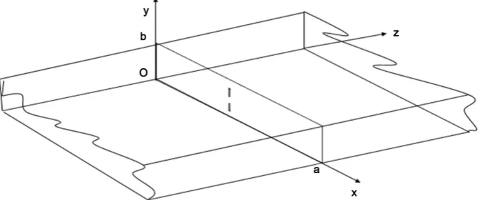
Figure 1. Dipole antenna inside an infinite waveguide.
density lying in the metal part including the source domain and its associated field to verify the boundary conditions. Next, the integral equation is solved by applying the MOM method using Galerkin procedure.
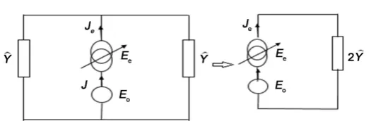
The waveguide is infinite in both z>0 and z<0 directions and the equivalent circuit of this structure are shown in Figure 2.
Two sources, a virtual and a real one, are being involved in the formulation process. We trait the case that the virtual source is of current type and the real one is of electric field type. Mode sources, case of E-sources: all higher-order modes reflected at the first discontinuity of the structure being attenuated at the location of the source, they see an infinite waveguide.
The real source E0=V F0 0 represents the excitation term associated to feeding
ele-ment. This kind of source must also respect the property of the located element, which should be smaller than the wavelength. It has amplitude V0 and depends on special
variables through F0. The function F0 acts as the shape function, which ensures
re-liable expression for the voltage and current case of rectangular source 0
1 F
δ = .
e
J is the virtual source defined on the metallic domain of the discontinuity surface and it is the problem unknown. Je is expressed as a series of known test functions
p
g weighted by unknown coefficients xp:
1
p
N
e p p
p
J x g
=
=
∑
Then the equivalent circuit of the studied structure is completed by addition the ter-minating operator Yˆ:
ˆ 2ˆ
IWG
Y= Y (3)
The admittance operator Yˆ is given by:
ˆ
mn IWG mn mn
Y =
∑
fα yα − fα (4)where
α =
TE
or TM , ymnα being modal admittance of the nth mode of an infinite
Figure 2.Equivalent circuit representation of a dipole antenna.
2 2
2 0 0
0 0
π π
TE mn
IWG mn
m n
a b
y
j j
ω µ ε γ
ωµ ωµ
−
+ −
= = (5a)
0 0
2 2
2 0 0
π π
TM IWG mn
mn
j j
y
m n
a b
ωε
ωε
γ
ω µ ε
− = =
+ −
(5b)
Applying the Kirchhoff laws, we can deduce the relation between virtual, real sources and its duals, as given in the following equation system:
1 0
ˆ e
e e
J J
E Y J− E
=
= −
(6)
Equation (6a) can be interpreted as the continuity relation of the current on the dis-continuity surface. Equation (6b) expresses the dis-continuity relation of the electric field. The current J is expressed in modal basis functions fmn m( ∈{0,1,2, ,M}) weighted by un-known coefficients Im:
0
M
m m m
J I f
=
=
∑
(7)Therefore, the application of the Galerkin’s method and Kirchhoff’s theorem leads to obtaining the simplified matrix representation as follows:
[ ]
[ ] [ ]
0 0 0
0 t
A
I V
X
A B
=
−
(8)
where
[ ]
A = F g0, p and[ ]
1
ˆ ,
q p
B = g Y g− .
4.2. Waveguide Walls Choice
The boundary conditions are defined on the contour of the structure. The better one can be chosen based on some criteria such as accuracy, rapidity and numerical conver-gence. The more the model basis respect the electromagnetic state of the real structure, the more it is adequate.
Electrical walls (EEEE). Magnetic walls (MMMM).
An electric-magnetic combination (EMEM): two perfect magnetic walls (M) on the lateral side and two perfect electric ones (E) on the bottom and the top.
The electric-periodic walls (EPEP): two periodic walls (P) on the lateral side and two perfect electric ones (E) on the bottom and the top.
Each virtual waveguide type is associated to a modal basis fmn. The studied struc-ture is invariant in y direction, and the waveguide is assured by a located source. Con-sequently the considered modal bases for every type are mentioned below:
For the electric wall:
( )
( )
( )( )
( )( )
( )( )
( )( )
2 2 2 2 2 2 2 2 0 0 4 cos sin 4 sin cos 4 cos sin 4 sin cos 0 2 sin 2 sin 0 y x y x y mn x x y x y x x y x y mn y x y x y m x y n kk x k y
ab
k k
TE
k
k x k y
ab
k k
k
k x k y
ab
k k
TM
k
k x k y
ab k k TE k x ab k y TE ab + = − + − + = − + = − = Magnetic wall: ( )
( )
( )( )
( )( )
( )( )
( )
( ) 2 2 2 2 2 2 2 2 0 0 4 sin cos 4 cos sin 4 sin cos 4 cos sin 0 2 sin 2 sin 0 y x y x y mn x x y x y x x y x y mn y x y x y n y x m kk x k y
ab
k k
TE k
k x k y
ab
k k
k
k x k y
ab
k k
TM k
k x k y
ab k k TM k y ab k x TM ab − + = + + = + = =
An electric-magnetic combination
( )
( )
( )( )
( )( )
( )( )
( )( )
2 2 2 2 2 2 2 2 0 0 4 sin sin 4 cos cos 4 sin sin 4 cos cos 0 2 cos 0 2 cos y x y x y mn x x y x y x x y x y mn y x y x y m x n y kk x k y
ab
k k
TE k
k x k y
ab
k k
k
k x k y
ab
k k
TM
k
k x k y
ab k k TE k x ab TM k y ab + = + + = − + = = −
An electric-periodic combination
( )
( )
( )( )
( )( )
( )( )
( ) 2 2 2 2 2 2 2 2 0 00 2 cos sin 2 sin cos 2 cos sin 2 sin cos 0 1 sin 0 1 x x y x y mn y x y x y y x y x y mn x x y x y m x kk x k y
ab
k k
TM
k
j k x k y
ab
k k
k
k x k y
ab
k k
TE
k
j k x k y
ab
k k
TE
j k x
ab TEM TE j ab − + = + + = + = = =
5. Results and Discussions
electric magnetic combination and electric periodic combination) to validate our choice of the electric wall.
The electric walls are chosen since convergence is reached quickly in addition de-scribes the environment we want to work with.
The results obtained show that the electrical walls simulate better the free space and convergence is reached quickly.
Concernant the virtual guide choice, all function basis (fmn) are littely equivalent, we
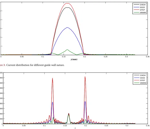
[image:7.595.59.551.264.686.2]may say that all guides atteind the same results at the convergence. However, according to the studied structures a base would be more appropriate in terms of convergence speed. To choose the introduced virtual guide type, we can respect either the real physical shape of current or that of the electric field (Figure 3 and Figure 4).
[image:7.595.49.549.269.478.2]Figure 5 showed the convergence of the imnput impedance as a function of the
Figure 3. Current distribution for different guide wall nature.
Figure 4. Electric field distribution for different guide wall nature.
0 0.05 0.1 0.15 0.2 0.25 0.3 0.35
0 1 2 3 4 5 6
y(mm)
||J
||(
A
/m
)
EMEM EEEE EPEP MMMM
0 0.05 0.1 0.15 0.2 0.25 0.3 0.35
0 200 400 600 800 1000 1200 1400 1600 1800 2000
y
||E
e
||
[image:7.595.45.550.495.687.2](a)
(b)
(c)
0 50 100 150 200 250 300 350 400 450 500
-20 0 20 40 60 80 100
nombre de fonction de base
z
in
Ne=8 Ne=10 Ne=12 Ne=16 Ne=20
0 50 100 150 200 250 300 350 400 450 500
0 50 100 150 200 250 300 350 400 450
nombre de fonction de base (NB=MB)
Z
in
Ne=10 Ne=12 Ne=16 Ne=18
0 50 100 150 200 250 300 350 400 450 500
-20 -10 0 10 20 30 40 50 60 70
nombre de fonction de base
Z
in
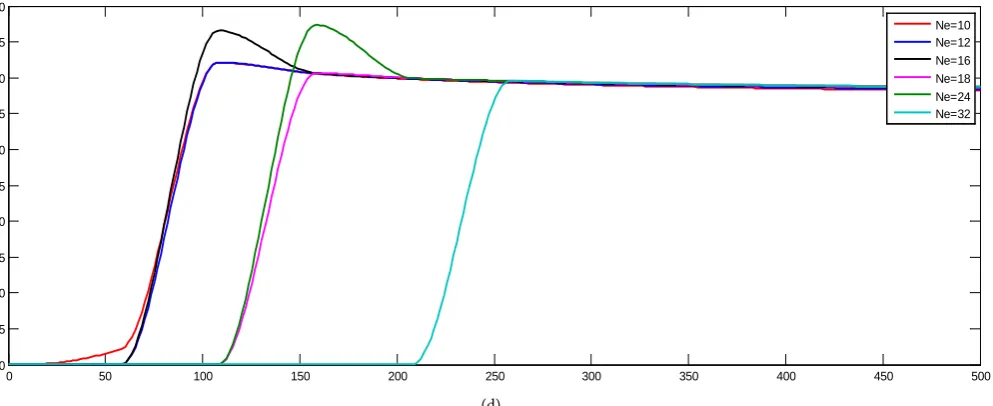
(d)
Figure 5. The input impedance as a function of the guide mode numbers for different test functions number at 1.8 GHz. (a) Electric wall (b) Magnetic wall (c) Electric-magnetic wall (d) electric-periodic wall.
guide mode numbers for different test functions. Four walls nature are taken into account, we note that the convergence was atteinded quickly using the electric wall and allow us to modulate the radiation inside a car. Figure 5(a) presents the input imped-ance variation as a function of the test function number Ne for different used basis function number Nb, which is fixed to 200 to ensure convergence. Studying the beha-vior of a dipole antenna both in free space and inside a rectangular infinite waveguide, it’s found that, MOM-GEC gives nearly the same results as that obtained in free space. Also a good study of convergence is elaborated to investigate the theoretical input im-pedance Zin evaluated by the MOM-GEC.
The convergence was obtained for Nb = 200 and Ne = 24. The current and electric
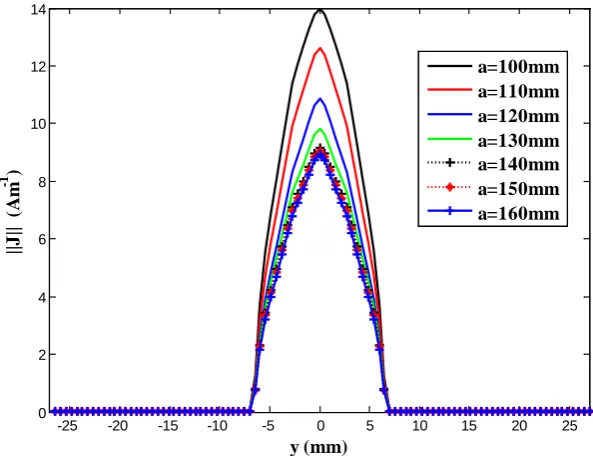
field distribution conforms to the theory and obey to the boundary conditions. An important parameter that may affect the antenna response is the placement of the waveguide walls. We present in Figure 6 the current density distribution along the di-pole antenna for different positions of electric walls. It’s found that, the current distri-bution is strongly affected by the lateral walls position. The separation distance have not any significant effect for a value that exceed a = 150 mm. In the following, the later-al wlater-alls positions are fixed at a = 150 mm and the b = 67 mm to insure the impact less of this parameter to further results.
Figure 7 and Figure 8 illustrate the electric field and current density evaluated by the MOM-GEC and obtained at convergence conforms to the theory with consideration to the boundary conditions.
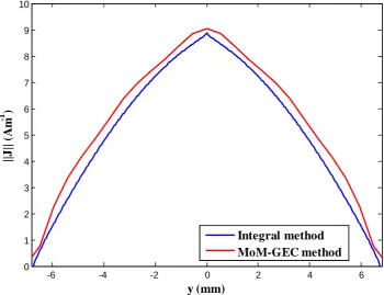
As it is shown in Figure 9, integral method and MOM-GEC gives nearly the same current distribution for a dipole antenna of length 78.85 mm which corresponds to
2
L=λ for an operating frequency f = 1.8 GHz.
0 50 100 150 200 250 300 350 400 450 500
0 5 10 15 20 25 30 35 40 45 50
Figure 6.Current density distribution as a function of a walls distance.
Figure 7.2D representation of the electric field density at f = 1.8 GHz.
Figure 8. 2D representation of the current density (A∙m−1) at f = 1.8 GHz.
-25 -20 -15 -10 -5 0 5 10 15 20 25
0 2 4 6 8 10 12 14
y (mm)
||J
|| (
A
m
-1 )
[image:10.595.165.552.517.683.2]Figure 9.Current distribution on a dipole antenna using integral method and MoM-GEC me-thod for an antenna length L = 78.85 mm and operating at f = 1.8 GHz.
The current distribution with the integral method take approximately a triangular form, the current distribution with MOM-GEC is a half sinusoid for the same operating frequency.
6. Conclusion
A method for analyzing the electromagnetic problem of a dipole antenna radiating at 1.8 GHz inside a rectangular waveguide antenna has been presented. Validation of the method was made with free space. Numerical convergence tests were achieved. The electric walls are chosen since convergence is reached quickly and describes the envi-ronment working (inside a car).
References
[1] Pearson, L.W. and Butler, C.M. (1975) Inadequacies of Collocation Solutions to Pockling-ton-Type Models of Thin-Wire Structures. IEEE Transactions on Antennas and Propaga-tion, 23, 293-298.
[2] Messaoudi, H., Aidi, M. and Aguili, T. (2016) Comparative Study of Electromagnetic Mod-eling of Dipole Antenna Radiated in Free Space and Inside a Rectangular Waveguide Using MoM-GEC. The 3rd International Conference on Automation, Control Engineering and Computer Science (ACECS-2016), 13, 522-527.
[3] Priyadharshini, K. and Brenie Sekar, G. (2014) Design of Dipole Antenna Using Mom. Proceedings of International Conference on Global Innovations in Computing Technology (ICGICT’14), 2, 1469-1476.
-6 -4 -2 0 2 4 6
0 1 2 3 4 5 6 7 8 9 10
y (mm)
||J
|| (
A
m
-1
)
[4] Aidi, M. and Aguili, T. (2014) Electromagnetic Modeling of Coupled Carbon Nanotube Dipole Antennas Based on Integral Equations System. Progress in Electromagnetics Re-search M, 40, 179-193. http://dx.doi.org/10.2528/PIERM14111404
[5] Banerjee, P. and Bezboruah, T. (2014) Some Aspects of Finite Length Dipole Antenna De-sign. Proceedings of the World Congress on Engineering, London, 2-4 July 2014, 307-312. [6] Harrington, R.F. (1968) Field Computation by Moment Method. The Mac-Millan
Compa-ny, New York.
[7] Baudrand, H. (1990) Representation by Equivalent Circuit of the Integral Methods in Mi-crowave Passive Elements. European MiMi-crowave Conference, 2, 1359-1364.
http://dx.doi.org/10.1109/euma.1990.336256
[8] Baudrand, H. and Bajon, D. (2002) Equivalent Circuit Representation for Integral Formula-tions of Electromagnetic Problems. International Journal of Numerical Modelling-Elec- tronic Networks Devices and Fields, 15, 23–57. http://dx.doi.org/10.1002/jnm.430
[9] Belhadj, H., Mili, S. and Aguili, T. (2011) New Implementation of the Conjugate Gradient Based on the Impedance Operator to Analyze Electromagnetic Scattering. Progress in Elec-tromagnetic Research, 5, 241-300. http://dx.doi.org/10.2528/pierb10072803
[10] Aguili, T. (2000) Modelisation des Composantes SFH Planaires par la Methode des Circuits Equivalents Generalisees. Thesis Manuscript, National Engineering School of Tunis, Tuni-sia.
Submit or recommend next manuscript to SCIRP and we will provide best service for you:
Accepting pre-submission inquiries through Email, Facebook, LinkedIn, Twitter, etc. A wide selection of journals (inclusive of 9 subjects, more than 200 journals)
Providing 24-hour high-quality service User-friendly online submission system Fair and swift peer-review system
Efficient typesetting and proofreading procedure
Display of the result of downloads and visits, as well as the number of cited articles Maximum dissemination of your research work