2017 2nd International Conference on Computer, Mechatronics and Electronic Engineering (CMEE 2017) ISBN: 978-1-60595-532-2
Integrated Navigation Method for RINS and Odometer
Hao ZHANG
1,*, Hai-tao QIU
2, Lei WANG
1and Tian-xiao SONG
1 1School of Instrumentation Science and Opto-electronics Engineering, Beihang University, Beijing 100191, China
2
Beijing institute of Aerospace Control Devices, Beijing 100039, China
*Corresponding author
Keywords: Integrated navigation, Rotation modulation, RINS and odometer.
Abstract. In order to meet the requirements of autonomous location and orientation in vehicle-mounted navigation system, this paper combined with rotation modulation technology and Kalman filter principle to establish an integrated navigation model for RINS and odometer. Based on the error models of the RINS and the odometer, the compositive error model and observation model of integrated system were deduced. The simulation experiments, which contained the comparison between integrated navigation system and RINS, were carried out. The results demonstrate the effectiveness of proposed integrated navigation method compared with the traditional way. The proposed method makes for the high-precision vehicle navigation system.
Introduction
The vehicle-mounted navigation system can provide accurate navigation information which includes the velocity, position and attitude for military vehicles on the battlefield continuously and independently. The long-term navigation can accumulate large navigation deviation, so it is necessary to restrain the inertial device errors to improve the navigation accuracy. Global positioning system (GPS) can also provide high-precision speed, location information and error is not accumulated with time. The SINS/GPS integrated navigation could improve the navigation precision [1]. But the information from GPS, which is owned by American military, can be easily disturbed and obscured and cannot be used in wartime [2]. The vehicle-mounted odometer is as autonomous as SINS, and the integrated navigation with SINS is the ideal navigation scheme [3]. There has been a great deal of research on the integrated navigation system about SINS and odometer. Zhang et al. have proposed an integrated navigation method for SINS and odometer and carried out a simulation to validate it [4]. Fu et al. have put forward the improved integrated navigation algorithm for SINS and odometer to refer to the difference between SINS position increments and dead-reckoning position increments per second as measurement [5]. However, the research about integrated navigation between RINS and odometer has not received enough attention, and the rotation modulation introduced to navigation system could improve the navigation precision further.
Rotation modulation technology is to use the rotary mechanism to drive inertial measurement unit (IMU) to rotate along gimbals, so as to modulate the sensors’ constant biases in the vertical plane of the rotational axis, which can obviously improve the precision of the inertial system. The integrated navigation between RINS and odometer can further improve the navigation accuracy. The common RINS includes single-axis RINS, dual-axis RINS and tri-axis RINS [6]. The research object in this paper is the single-axis RINS, which consists of one gimbal, presented as azimuth axes.
described. The mathematical formulas about the odometer output model are deduced in section 3. Section 4 presents the error model and observation model about the integrated navigation system. At the last, the simulation results is presented and the conclusion is drawn in section 5 and 6.
The Rotation Modulation Principle
The main research object is single-axis RINS, which owns one gimbal. The IMU can rotate along with the framework in a rotation period to restrain constant biases in the horizontal plane. The error depression principle of rotation modulation technology is analyzed by single-axis RINS.
In order to describe the movement of IMU, it is necessary to make detailed description about several related coordinate frame definitions as follows. A body frame (b-frame) is defined as right-forward-upward. The navigation frame (n-frame) is defined as east-north-up. The detailed definition of the platform frame (p-frame) is orthogonal coordinate system coincided with sensor frame approximately after the installation errors are compensated. When the IMU rotates along with the gimbals, the output of the inertial sensors in p-frame is modulated as the sinusoidal quantity in b-frame instead of constant, which can be integrated to big navigation error in SINS for a long time. The reasonable rotation modulation makes for higher-precision navigation performance.
When the IMU rotates along with the OZp axis for the time t, the direction cosine matrix to
transform the output of inertial components from b-frame to p-frame is
( )
( )
( )
( )
( )
cos sin 0 sin cos 0
0 0 1
T
p b
b p
t t
C t t C
ω ω
ω ω
= − =
(1)
The output of gyros and accelerometers are denoted as p ip
ω and p
f . According to the
transformation matrix b p
C , the output in b-frame can be expressed as
[
0 0]
Tb b p ib p ip b b p
p
C
f C f
ω ω ω
= + −
=
(2)
The real output of gyros and accelerometers in p-frame are expressed as p ipT
ω and p
T
f . The constant sensors’ biases contain three gyro drifts, represented as εx,εy,εz, and three accelerometer
biases, denoted as ∇x,∇y,∇z. The output of inertial sensors in p-frame can be represented as
[
0 0]
T T
p p
ip ipT x y z p p
T x y z
f f
ω ω ε ε ε ω
= + +
= + ∇ ∇ ∇
(3)
According to Eq. 1 and Eq. 3, the Eq. 2 can be expressed as
( )
( )
( )
( )
( )
( )
( )
( )
cos sin cos sin
cos sin cos sin
x y
b b
ib ibT y x
z
x y
b b
T y x
z
t t
t t
t t
f f t t
ε ω ε ω
ω ω ε ω ε ω
ε
ω ω
ω ω
−
= + +
∇ − ∇
= + ∇ + ∇
∇
(4)
From Eq. 4, the constant errors of gyros and accelerometers in OXb axis and OYb axis are modulated as the periodic quantity, but the errors in OZb axis is still the same. The rotation
types will be described as follows through the figure.
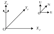
p
Z
p
Y
p
[image:3.612.258.351.82.141.2]X
Figure 1. Rotation strategy.
In order to describe the rotation strategy clearly, the definition of modulation cycle should be introduced. The time which contains the whole rotation mode is called a modulation cycle. During the navigation, RINS will repeat the rotation mode of a modulation cycle. The detailed rotation mode in a modulation cycle will be described for above rotation strategies. In rotation strategy from the Fig. 1, the IMU rotates 360° along with OZp axis in the clockwise and anticlockwise direction
alternately and continuously.
The Output Model of Odometer
From the vehicle-mounted odometer, we can get the distance increment in an impulse sampling time. Based on the distance increment and impulse sampling time, the velocity can be calculated and regarded as the output. This paper will make use of the velocity from odometer to integrate with RINS. The related coordinate frame should be described first. The detailed definition of measurement frame (m-frame) is: the y axis is coincided with direction of forward motion, x axis is perpendicular to y axis coincided with the right hand of body, z axis is defined according to right-hand rule.
At the time t, the vehicle speed measured from odometer is vD, which is represented in m-frame as
[
0 0]
Tm
D D
v = v . (5) Based on the transformation relationship from m-frame to b-frame, the velocity output in b-frame can be obtained as follows.
b b m D m D
v =C v (6)
If the pitch, roll and azimuth installation angle of RINS relative to the vehicle are αθ,
α
γ andψ
α
, the direction cosine matrix from m-frame to b-frame can be expressed as:cos cos sin sin sin sin cos sin cos cos sin sin cos sin sin cos sin cos cos sin sin cos cos sin
sin cos sin cos cos
r r r r
b
m r r r r
r r
C
ψ θ ψ ψ θ ψ θ ψ
ψ ψ θ ψ θ ψ ψ θ
θ θ θ
α α α α α α α α α α α α
α α α α α α α α α α α α
α α α α α
+ −
= − + − −
−
. (7)
The velocity components in b-frame can be deduced from the Eq. 5-7
sin cos sin cos cos cos cos cos
sin sin
b
D D D D
v v K N
ψ θ ψ θ
ψ θ ψ θ
θ θ
α α α α
α α α α
α α
= =
(8)
Where KD is odometer scale factor, and ND is the number of pulses between samplings. From
above equation, the velocity measured from odometer is not influenced from the roll installation angel. Therefore, the scale factor error δKD and pitch and azimuth installation errors δαθ,δαψ are
taken into account. The installation angels αθ and αψ can be regarded as infinitesimal quantity
(
)
(
)
1 0
1 1
0 1
b b
D D D d
v K v
ψ
ψ θ
θ δα
δα δα δ ω
δα
= − + +
−
, (9)
Where ωd is stochastic noise. Ignoring the second-order infinitesimal quantity which includes
D
K ψ
δ δα and δKDδαθ, the velocity error b D
v
δ can be expressed as
b b b b
D D D D d
v v v M K
ψ
θ δα
δ δ ω
δα
= − = +
. (10)
T bx by bz
D D D
v v v
is component of velocity vDb, and the matrix b
M is expressed as
0
0 by bx
D D
b bx by bz
D D D
bz by
D D
v v
M v v v
v v
= −
−
. (11)
The Integrated Navigation Model
The RINS can modulate the constant errors of the inertial sensors by using its own rotation mechanism to improve the positioning accuracy of the vehicle navigation system. In addition, the navigation precision could be further improved by the RINS/odometer integrated navigation system. The integrated navigation model is able to maintain high autonomy. The 16-dimension error states of the RINS and odometer integrated system is established. The error model and observation model of integrated navigation system are described. The integrated navigation model is resolved by a closed-loop Kalman filter, which can compensate RINS and odometer with the estimates. The integrated navigation algorithm is shown in Fig. 2.
Figure 2. The integrated navigation algorithm.
The error states of integrated navigation model consist of velocity errors δVE,δVN,δVU, position
errors δL,δλ, attitude errors φE,φN,φU, gyro drifts and accelerometer biases in the sensitive axis
x
ε ,εy,εz,∇x,∇y, and the scale factor error, installation angle errors δKD,δαϕ,δαθ are contained.
The 16-dimension error states vector of integrated model is established as follows.
( )
E N U E N U x y z x y D TX t =δV δV δV δL δλ φ φ φ ε ε ε ∇ ∇ δαϕ δK δαθ (12)
The equation of state is expressed as
( )
( ) ( )
( ) ( )
X t =F t X t +G t W t . (13)
The parameters, including δKD, δαϕ and δαθ, can be regarded as constant errors once the
1 3 3
3 13 3 3
0 0 0
F
F ×
× ×
=
. (14)
Where F1 is state-transition matrix according to the error equations of RINS. From the Eq. 14,
the matrix F is similar to RINS/GPS integrated navigation system.
In the integrated navigation process, velocity measured from odometer is transformed to n-frame and compared with the calculated velocity from the RINS. The measurement equation is represented as:
ˆ c n p b
p b D
v v C C v
∆ = − (15)
Where ˆn p
C expresses the transformation matrix with error from p-frame to n-frame.
According to Eq. 10 and ignoring the second-order infinitesimal quantity, the above equation can be expressed as
(
)
n n n p b
p b D
v δv φ v C C δv
∆ = + × − (16)
For the sake of the description, the matrix n b
C can be assumed to be
11 12 13
21 22 23
31 32 33
n n p b p b
C C C
C C C C C C
C C C
= =
. (17)
Based on Eq. 16 and Eq. 17, the measurement equation could be calculated as
11 12 13
21 22 23
31 32 33
0 0
0
0 0
n n n by bx
x x z y E D D
n n n bx by bz
y y z x N D D D D
n n n bz by
z z y x U D D
v v v v C C C v v
v v v v C C C v v v K
v v v v C C C v v
ϕ
θ
δ φ δα
δ φ δ
δ φ δα
∆ −
∆ = + − + −
∆ − −
(18)
Simulation
In order to prove the effectiveness of the proposed integrated navigation model, the simulation designed for single-axis RINS and odometer is carried out. The simulation contains two sections. The different navigation performance between only the RINS and RINS/odometer is performed in part one. In part two, the simulation about comparison between integrated navigation system combined with RINS or SINS is carried out.
The initial placement location of system, namely b-frame, is in accord with n-frame roughly. The IMU mainly consists of three fiber gyros and three quartz accelerometers, the accuracy of which are 0.05°/h and 50ug respectively. The random walk of gyros is 0.001 / h. The rotational angular
velocity of motor is selected as 6 °/s. The initial position is located at 116.35° E, 39.98° N. The initial errors are 5″, 5″ and 2′. The carrier vehicle runs along the north direction at a constant speed of 15m/s for 30mintues. The scale factor error of odometer is set to 0.001, the pitch and azimuth installation errors are selected as 0.1°.
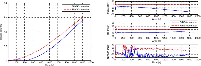
Figure 3. Navigation errors of RINS and RINS/odometer.
Figure 4. Navigation errors of SINS/odometer and RINS/odometer.
From the results of simulation, we can get several results as follows.
1) In the integrated navigation process, the position error and attitude errors can retain in certain precision range for a long run from the simulation results. It can prove that the navigation errors could be effectively estimated and compensated through the integrated navigation.
2) There’s not much difference in position error. The attitude errors from the RINS/odometer could be less than the SINS/odometer. The improvement of attitude precision in RINS/odometer is remarkable by comparison. The rotation modulation can effectively modulate the inertial sensors’ errors to improve the precision of integrated navigation system.
Conclusion
The RINS/odometer integrated navigation method based on closed-loop Kalman filter is proposed in this paper. Through analyzing the error suppression principle of rotation modulation, establishing the error model equation and the measurement equation, the integrated navigation Kalman filter model is accomplished. The simulation results show that the precision of navigation output has been improved obviously through the RINS/odometer integrated navigation with well-designed rotation modulation.
Reference
[1]Grewal M S, Weill L R, Andrews A P. Global positioning systems, inertial navigation, and integration / Mohinder S. Grewal, Lawrence R. Weill, Angus P. Andrews[C]// Springer New York, 2004:23-39.
[2]Yan G, Qin Y, Bo Y. On Error Compensation Technology for Vehicular Dead Reckoning (DR) System [J]. Journal of Northwestern Polytechnical University, 2006, 24(1):26-30.
[3]Rogers R M. Applied Mathematics in Integrated Navigation Systems, Third Edition [J]. Reston 0 200 400 600 800 1000 1200 1400 1600 1800 2000
0 80 160 240 320
Time (s)
p o s it io n e rr o r( m ) RINS RINS/odometer
0 200 400 600 800 1000 1200 1400 1600 1800 2000 -20
-10 0 10 20
Time (s)
p it c h e rr o r( ")
0 200 400 600 800 1000 1200 1400 1600 1800 2000 -10
-5 0 5 10
Time (s)
ro ll e rr o r (" ) RINS RINS/odometer
0 200 400 600 800 1000 1200 1400 1600 1800 2000 -50
0 50 100 150
Time (s)
a z im u th e rr o r (" )
0 200 400 600 800 1000 1200 1400 1600 1800 2000 0
0.8 1.6 2.4 3.2
Time (s)
p o s it io n e rr o r (m ) SINS/odometer RINS/odometer
0 200 400 600 800 1000 1200 1400 1600 1800 2000 -60
-40 -20 0 20
Time (s)
p it c h e rr o r( ")
0 200 400 600 800 1000 1200 1400 1600 1800 2000 -20
-10 0 10 20
Time (s)
ro ll e rr o r( ") SINS/odometer RINS/odometer
0 200 400 600 800 1000 1200 1400 1600 1800 2000 -40
-20 0 20 40
Time (s)
[image:6.612.107.502.231.362.2][4]Zhang X, Yang G, Zhang C. Integrated navigation method for SINS and odometer [J]. Journal of Beijing University of Aeronautics & Astronautics, 2013.
[5]Qiang-Wen F U, Qin Y Y, Zhou Q. Improved Vehicular SINS/Odometer Integrated Navigation Algorithm [J]. Measurement & Control Technology, 2013.