2018 International Conference on Modeling, Simulation and Optimization (MSO 2018) ISBN: 978-1-60595-542-1
Airflow Field Simulation and Structural Optimization of High Voltage SF
6Circuit Breaker Interrupter Based on Orthogonal Experiment
Hao ZHANG
*, Yu-jing GUO, Yong-qi YAO, Zhi-jun WANG and Bo ZHANG
Pinggao Group Co., Ltd, Pingdingshan, China *Corresponding author
Keywords: SF6 circuit breaker, Interrupter, Airflow field simulation, Structural optimization,
Orthogonal experiment.
Abstract. In order to improve the high voltage SF6 circuit breaker breaking performance, the simulation scheme of multi-parameter optimization design of circuit breaker interrupter is proposed based on the orthogonal experiment method. Through numerical modeling and simulation of interrupter airflow field, the effects of three parameters such as of cylinder diameter, expansion chamber diameter and nozzle throat diameter on the breaking performance of circuit breakers were studied.An interrupter structure with the best breaking performance was obtained. Simulation results show that, among the above three parameters, the nozzle throat diameter has the greatest influence on the breaking performance of circuit breakers.The smaller the nozzle throat diameter, the stronger the breaking performance of the circuit breaker. This is of great significance to the multi-parameter optimization design of high voltage SF6 circuit breaker interrupter structure.
Introduction
High voltage circuit breakers are important control and protection devices in power system. They can break, close and carry the normal, abnormal and short circuit currents of power system. Therefore, breaking performance is the most important technical indicators of high voltage circuit breaker [1,2].
During the breaking process of the high voltage SF6 circuit breaker, the arc generated between the moving contact and the static contact belongs to the plasma. The process of arc development is a complicated process of the interaction between electromagnetic field, temperature field and airflow field. The burning and extinguishing characteristics are closely related to the structure of the interrupter [3-5]. The nozzle and cylinder is the core components of the interrupter, and its shape has a significant impact on the gas pressure and flow rate during the arc extinguishing process.
In order to study the influence of cylinder, expansion chamber and nozzle throat diameter on the breaking performance of circuit breakers and get the best interrupter structure through less simulation calculation, a high voltage SF6 circuit breaker is taken as the research object in this paper. Firstly, the simulation model of the flow field during the breaking process of interrupter is set up, and the parameters of flow field such as pressure, temperature and flow rate are obtained by numerical calculation. Secondly, based on the idea of orthogonal experiment method, a simulation program of multi-parameter optimization design for interrupter was designed. Thirdly, according to the simulation results, the influence of the above three parameters on breaking performance was analyzed, and an interrupter structure with the best breaking performance is proposed.
Simulation Model and Characteristics of Airflow Field in Interrupter
Mathematical Model of Airflow Field Simulation in Interrupter
current 63kA. The mathematical model of arc is established according to the general conservation equations:
V
St
(1) where
is the variable to be solved, meanwhile
and V is the density and velocity of the gas respectively. The source term S and the diffusion coefficient are listed in Table 1, where all [image:2.612.122.492.210.298.2]notations have their conventional meaning [6,7].
Table 1. Terms of governing equations.
Equation φ Γφ Sφ
Continuity l 0 0
z-momentum w μl+μt P/ z J Br viscous terms r-momentum v μl+μt P/ r J Br viscous terms Enthalpy h ( kl + kt)/cp σE 2- q + dP/dt +viscous dissipation
PTFE mass concentration cm ρ( Dl + Dt) 0
Simulation Model of Airflow in Interrupter
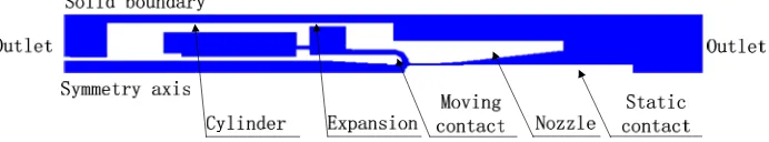
[image:2.612.135.481.439.503.2]In order to ensure the quality of the grid and the accuracy of the calculation, it is necessary to simplify and equivalent the initial structure of the arc extinguishing chamber before modeling. Based on the simplified geometric model, a two - dimensional axisymmetric simulation model is established. According to the actual use of the product conditions, set the initial conditions of simulation, which gas velocity is 0, the temperature is 300K, the circuit breaker inflation pressure is absolute pressure 0.62MPa. In the simulation model, set the two outlets, the outlet pressure is always maintained for the initial pressure of the interrupter. The simulation model and the boundary condition are shown in Figure 1.
Figure 1. Simulation model and boundary condition diagram.
Simulation Analysis of Airflow Field in Interrupter
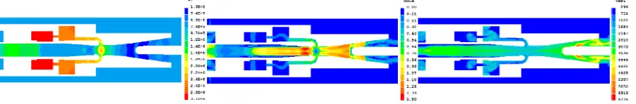
arc shape is elongated. This shows that the arc is in the ideal arc extinguishing environment, which is conducive to breaking the circuit breaker.
Figure 2. The pressure, Mach number and temperature cloud diagram at the current zero time.
Optimization Design of Interrupter Structure Based Orthogonal Experiment
Orthogonal Experiment Method Introduction
Orthogonal experiment method is a scientific method of organizing the experiment. It uses the orthogonal table to design the test plan and analyze the test results. It can select a few representative test conditions from a lot of test conditions and find out the best or better test data. Orthogonal experiment method can not only solve the multi-factor optimization problem, but also can be used to analyze the impact of various factors on the test results, so as to seize the main factors.
Orthogonal experiments need to select the appropriate orthogonal table. Orthogonal tables are represented as Ln (tc), L is the code of the orthogonal table, n is the number of trials, t is the number of levels, and c is the number of columns. In each column of the orthogonal table, different numbers appear in equal numbers, the numbers in any two columns are arranged in a perfect and balanced manner, and each level of each factor touches each level of another factor [8].
Optimization Indicators and Optimization Parameters
Before the multi-parameter optimization of high voltage SF6 circuit breaker interrupter, we must first determine the optimization index, which needs to reflect the breaking performance. Because the arc extinction environment is extremely complicated before the current zero time, in order to study the influencing factors of the breaking performance of the interrupter, it is necessary to pay attention to the temperature field and the flow field state in the arc area at the current zero time.
When the current crosses zero, the gas temperature around the arc has a decisive influence on the breaking of the interrupter. In theory, when the current zero time, the lower the temperature between the moving contact and the static contact, the more conducive to breaking. However, as the arc just extinguished, the high-temperature gas generated by the arc energy has not yet been completely cooled, and the temperature in this area is generally several thousand K. Before the current zero time, the high thermal conductivity of the gas is conducive to arc cooling. Therefore, when the temperature is between 2000-3000K, SF6 has a higher thermal conductivity, which is conducive to arc cooling and interrupter breaking.
In addition, it is generally accepted that the magnitude of the flow rate represents the enthalpy flow rate or the arc energy discharge rate through the nozzle. Theoretically, when the flow of the nozzle throat is relatively large at the current zero time, the easier the arc energy is discharged, and the circuit breaker has strong breaking capacity.
Therefore, the optimization index of this paper is the maximum arc temperature (T) and the nozzle throat mass flow (G) at the current zero time.
Simulation Program Design
In order to separately consider the influence of interrupter structure parameters on the breaking performance, the other simulation parameters outside the structure dimensions are set uniformly as follows: the breaking current is 63kA, the arcing time is 10ms.
[image:4.612.96.521.187.250.2]In order to study the influencing factors of breaking and find out the main influencing factors, the orthogonal experiment was used to optimize the nozzle throat diameter, expansion chamber diameter and cylinder diameter. The corresponding factors - levels are shown in Table 2.
Table 2. Interrupter multi-parameter optimization factor - level table.
Leve
r No. Nozzle throat diameter /mm No. Expansion chamber diameter /mm No. Cylinder diameter /mm
1 A1 30 B1 130 C1 110
2 A2 35 B2 140 C2 120
3 A3 40 B3 150 C3 130
According to the number and level of factors, L9 (34) orthogonal table is chosen, which means that 9 experiments are required and up to 4 factors can be observed, each factor is 3 levels.
Interrupter Structural Parameters Optimization
In the analysis of the orthogonal experiment results, the main factors that affect the breaking performance of the interrupter are firstly identified, followed by the study of the influence law of each factor, finally the best combination of design parameters is obtained.
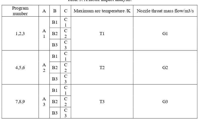
[image:4.612.109.505.388.626.2]Taking A factor as an example, using the range analysis method, the data of nine kinds of conditions were extracted and analyzed. Analysis results are shown in Table 3.
Table 3. A factor impact analysis.
Program
number A B C Maximum arc temperature /K Nozzle throat mass flow/m3/s
1,2,3 A1
B1 C1
T1 G1
B2 C2
B3 C
3
4,5,6 A2
B1 C1
T2 G2
B2 C2
B3 C3
7,8,9 A3
B1 C1
T3 G3
B2 C2
B3 C3
Among them, T1-T3 and G1-G3 are the targets average values under the three conditions respectively combination. Because the various levels of B and C under each conditions combination occur on average, the target average values reflect the effects of different levels of A. Performing the same operation on influencing factors B and C results in T4-T9 and G4-G9. The targets average values and range results are shown in Table 4.
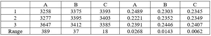
Table 4. The targets average values and range results.
A B C A B C
1 3258 3375 3393 0.2489 0.2303 0.2345
2 3277 3395 3403 0.2221 0.2352 0.2349
3 3647 3412 3385 0.2391 0.2446 0.2407
Range 389 37 18 0.0268 0.0143 0.0062
Finally, draw the indicator - factor diagram as shown in Figure 3 and Figure 4. As can be seen from Figure 3, A factor (nozzle throat diameter) has the greatest influence on the maximum arc temperature T. The smaller the nozzle throat diameter is, the lower the maximum arc temperature is. The influence of factor B (expansion chamber diameter) and factor C (cylinder diameter) on maximum arc temperature is relatively small. Therefore, considering the index of maximum arc temperature, A1B1C3 is the best combination. It can be seen from the Figure 4 that the A factor (nozzle throat diameter) has the greatest effect on the nozzle throat mass flow G at current zero time, followed by the factor B (expansion chamber diameter) and the factor C (cylinder diameter). Therefore, A1B3C3 is the best combination considering the nozzle throat mass flow.
[image:5.612.127.486.65.127.2]
Figure 3. T indicator - factor relationship. Figure 4. G indicator - factor relationship.
In the maximum arc temperature and nozzle throat mass flow indicators, A1 and C3 are the best program, but B factors are contradictory. Based on simulation and experimental experience, we choose C3 as the optimal solution. In summary, the recommended optimal combination of parameters is A1B3C3.
Summary
The circuit breaker airflow field of the initial design is simulated. The pressure, temperature and Mach number of the arc chamber at current zero time are obtained, and the rationality of the initial design structure is proved.
Based on the orthogonal experiment method, a multi-parameter optimization design scheme of interrupter was designed. According to the simulation results, the influence of nozzle throat diameter, expansion chamber diameter and cylinder diameter on the breaking performance was analyzed. An interrupter structure with the best breaking performance is proposed.
The simulation results show that the nozzle throat diameter has the greatest influence on the maximum arc temperature and the nozzle throat mass flow among the three parameters. The smaller nozzle throat diameter can ensure the lower arc temperature and the larger throat flow at the current zero time, so that the circuit breaker has a strong breaking performance.
References
[1]Yan J.D., Zhang Q., and Cao K. Thermal interruption performance of SF6 replacement gases and its dependence on material properties [J]. High Voltage Apparatus, 2016, 52(12): 23-30.
[image:5.612.138.478.255.373.2][3]Zhong J., Guo Y., and Zhang H. Pressure and arc voltage measurement in a 252 kV SF6 puffer circuit breaker [J]. Plasma Science and Technology, 2016, 18(5): 490-493.
[4]Zhang Q., Yan J.D., and Fang M.T.C. Current zero behavior of an SF6 nozzle arc under shock conditions [J]. Journal of Physics D Applied Physics, 2013, 46(16): 165203-165217.
[5]Zhang Q., Yan J.D., and Fang M.T.C. The modeling of an SF6 arc in a supersonic nozzle: I. Cold flow features and dc arc characteristics [J]. Journal of Physics D Applied Physics, 2014, 47(21): 744-759
[6]Yan J.D., Fang M.T.C., and Hall W. The development of PC based CAD tool for auto-expansion circuit breaker design [J]. IEEE Transactions on Power Delivery, 1999, 14(1): 176-181.
[7]Pei Y., Zhong J., Zhang J., and Yan J.D. A comparative study of arc behavior in an auto-expansion circuit breaker with different arc durations [J]. Journal and Physics D Applied Physics, 2014, 47(33): 335201.