2017 International Conference on Computer, Electronics and Communication Engineering (CECE 2017) ISBN: 978-1-60595-476-9
Automobile Passive Keyless Entry Based ON RFID
Jing-ru JIA
, Xiao-dong CHENG
*and Pei-rong WANG
College of Electronic Information Engineering, Inner Mongolia University, Hohhot, 010021, China *Corresponding author
Keywords: RFID, Dual frequency communication, RSSI.
Abstract. This system via RFID's dual-frequency communication to design a automobile passive keyless entry system. And They sent high frequency 433 MHZ and low-frequency 125 KKZ to communicate with each other. This paper mainly introduces the design of the on-board reader and the intelligent key. The test shows that the system is stable in any environments, and it can recognize the driver correctly. This system can apply to all portal systems.
Introduction
With the rapid development of science and technology in recent years, a new type of keyless entrance guard system (PKE: Passive Keyless Entry)show in the modern car market, compared with the traditional remote control car keys entrance guard system (RKE: Remote Keyless Entry), the PKE system has great advantage, it is more secure, more convenient and more comfortable. The PKE system are implemented through the RFID radio frequency identification technology, includes two main parts, the smart car keys and on-board reader. They sent high frequency 433 MHZ and low-frequency 125 KKZ to communicate with each other. As long as the smart key is near the car, the door will open automatically.
The PKE system in this paper adopts the roll code encryption technique and RSSI positioning method, which make the PKE system safer and more convenient. It also added the original RKE function to remotely control the switch on the door.
Design Principle of Automobile PKE System Based on RFID Technology
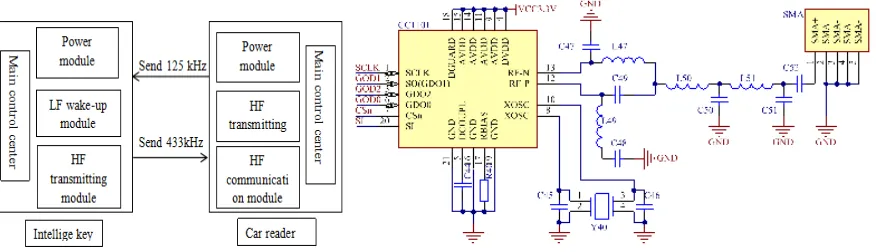
Figure 1. Intelligent keys and on-board reader. Figure 2. CC1101Circuit diagram communication block diagram Figure.
Hardware Design based on PKE System The Design of on-board Reader
The on-board reader is the control part of the intelligent PKE system, which is mainly composed of the micro control unit, the radio frequency processing module, the low frequency transmitting module, the communication module, the power module and so on.
The core processor of the microcontroller is STM32F103. Its core is ARM32 bit Cortex-M3 CPU. It has many advantages, such as sleep, shutdown, standby, high reliability and low power consumption, which are the factors for the microprocessor.
The reader of the radio frequency processing chip is CC1101 chip, the circuit diagram is shown in Figure 2.CC1101 is a low cost and high performance UHF transceiver, designed for low-power wireless applications, mainly to complete the remote data transceiver. Circuit design using CC1101 433MHz frequency band. It integrates a highly configurable modem. The demodulator can support different modulation formats, the data transmission rate can reach 500Kbps. CC1101 communicates with the host through SPI interface, and uses ISO/IEC 1800-7 air interface protocol to design the communication format.[1]
[image:2.612.89.527.70.196.2]
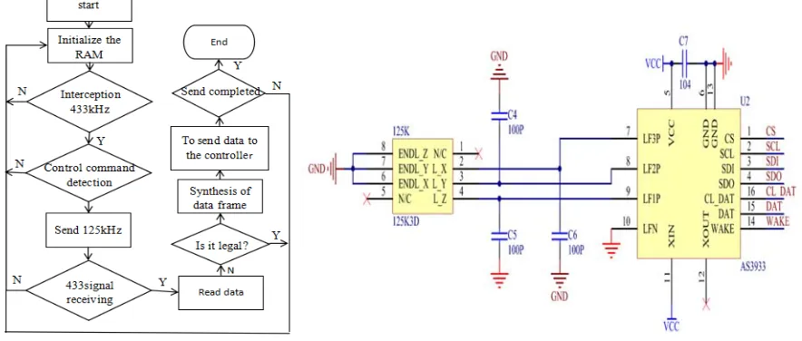
Low frequency transmitting reader of vehicle main control chip directly through the PWM waves to complete generation and control of 125KHZ,show as the 125KHz transmission circuit diagram of Figure 3. The 125KHZ antenna use KGEA-BFCR-B-0500J antenna of PREMO.
Figure 3. 125KHZ transmission circuit diagram. Figure 4. AS3933Port function.
[image:2.612.113.504.484.567.2]Figure 5. 125KHZ Wake up signal frame format. Figure 6. Output waveform.
Because of the on-board reader is heavy load, the software design is more complicated. Firstly, the main control set the initial configuration of each module, initialization timer. Secondly, by controlling the timer to generate the 125KHZ low-frequency wake-up signal data, and sent by polling. Finally, when the high frequency receiving module receives the signal transmitted by the intelligent key, the reader carries out corresponding processing and uploads the data to control the opening and closing of the door. And then into the next cycle. The working flow chart of the reader is shown in Figure 7.
[image:3.612.89.531.319.507.2]Figure 7. On-board reader work flow chart. Figure 8. Low frequency wake-up receiver module circuit.
Intelligent Key Design
Intelligent key is mainly composed of a micro controller module, RF transmission module, LF wake-up receiver module and power module.
Intelligent key micro control unit using MSP430G2553 20 pin chip. The high frequency transmission module of the intelligent key adopts the CC1101 wireless chip, and the hardware circuit is basically the same as the reader, but the RAINSUN part of the antenna is used in the 433MHZ part of the antenna. This design makes the volume of the intelligent key smaller.
frequency antenna.[3]The performance of low frequency antenna is closely related to the quality factor Q. The typical Q value in the design is 15. The circuit of the low frequency wake-up receiver module is shown in Figure 8.
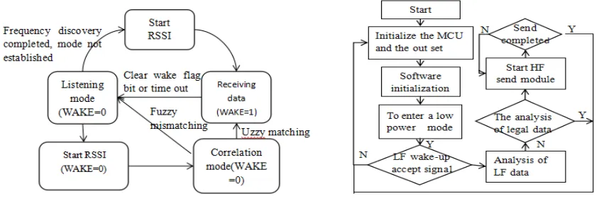
First of all, using SPI of MCU set AS3933 clock and other working registers to achieve low frequency wake-up data received. AS3933 working mode as shown in Figure 9.Among them, the design uses the ON/OFF mode, open Scan mode, channel 1, 2, 3 all open, use the Pattern of 32 bits, the frequency of wake up set to 59-150KHZ, use the ASK modulation, no gain attenuation. Set the lead code for the 0x5B5B, and set the R6 register to wake up the code format of 16 bits, The preparation of 16 bit wake up the code format. The low frequency carrier frequency detect 125KHZ head, lead code, wake type code set, when meet all set requirements, the AS3933 WAKE pins produce a high level signal, then the CLDAT pin output maitesi special clock pulse waveform restoration, and decoding the data in the DAT output pin mendez.
In the intelligent power supply part, in order to achieve low power consumption, high frequency module part uses the BL1551 switch module power supply. The main control chip is used to control the BL1551 to achieve the opening and closing of the high frequency partial voltage. This design uses 3V battery type CR2032 lithium manganese button battery. Intelligent key work flow diagram in Figure 10.
[image:4.612.94.516.290.432.2]
Figure 9. AS3933 work model. Figure 10. Intelligent key work flow diagram.
Rolling Code Encryption Technology
KEELOQ is a kind of complex nonlinear encryption algorithm, this algorithm can not only be realized by hardware, but also can be encrypted by software. The system is used in the intelligent key to install a KEELOQ encryption module, and in the end of the on-board reader using software decoding. This allows you to set the number of password pairing, the general situation of the correct pairing can only be successful once, if there are multiple pairs, it must be illegal pairing. Set the maximum number of times to match the password, if the number of times more than this, then the implementation of the lock program, after a certain time to match. This can effectively prevent the illegal pairing, and higher security .
In KEELOQ technology, we need to match the system, we call this matching process "learning", the purpose is to clear the original stored in the storage area of information and learn new information. Every time must be at least one-way "learning" in a rolling code encryption, So that every time the new password is randomly generated in the first pair of garbled when used, and after each learning operation generates a garbled are not the same, also have no regularity between each other. After learning the generated password, we call it the security code. Every time after the encoding and decoding operation, the security code stored that is invalid, if the next time you receive a security code when such a system not considering learning to use the security code of the one before, so it can effectively prevent the deciphered.
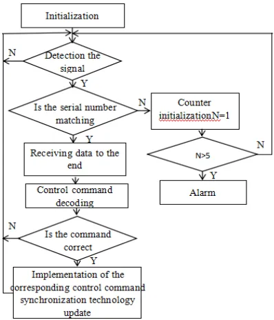
Figure 13. KEELOQ system software flow chart. Figure 14. Keyless entry flow chart.
Control Software Design
The software design of the system consists of two parts, one is the keyless entry control software, and the other is the control software of the common key open and close.
Keyless entry control software design process is shown in Figure 14.The on-board reader in a sleep state at beginning, when the intelligent key into the low-frequency excitation signal area, on-board reader will be awakened into the working state, the on-board reader sends a low frequency excitation signal to the intelligent key. When the intelligent key received low-frequency excitation signal, calculated by RSSI is in the low frequency range signal recognition, if it is, the intelligent key sends high-frequency 433KHz signal to the on-board reader .The on-board reader verifies that the ID number of the smart key is correct, and if so, the unlock command is executed.
The common key locking control flow diagram as shown in Figure 15, when the intelligent key sending unlock command, it will send a set of data to the on-board reader , verifying the key ID is correct, if the verification is correct, will decode, after completion will be in accordance with the command sent by the CAN bus to send unlock / lock command.
[image:5.612.86.527.527.667.2]
Figure 15. The flow chart of opening and closing of common key. Figure 16. Actual location diagram.
key receives the low frequency signal, it will calculates the strength of their location to see if they are in the recognition area, if it is, it will transmit the high frequency signal, the corresponding realization of communication, implementation of the locking or unlocking command if correct.
Summary
In this paper, the use of RFID based intelligent car access control system, using 125KHZ low frequency excitation, 433MHZ high frequency communication, you can achieve a better communication and adapt to a variety of complex environment. Through the test, the outdoor complex environment can maintain good stability. The calculation formula of RSSI signal intensity is used to calculate whether the intelligent key is within the range of excitation. The paper shows that the RFID technology can ensure that the system can correctly identify the driver in any case, the driver close to the car in the automatic recognition or away from the car can be very good to their identity, automatically open or close the door. This system not only solves some problems existing in the original control mode, but also has important significance for improving the safety, comfort, economy and operation of the vehicle.
Acknowledgement
I appreciate the teacher of Xiaodong Chen,s help. Whatever in academic or in life, he helps me a lot. All of these will benefit me for the rest of my life. And thanks to everyone around me, my classmates, my friends and my family, not only gave me a relaxed and active atmosphere, but also gave me a lot of encouragement in my spirit.
Then thank you for funding from the National Science Foundation. They give me a platform to show my design results. It also helps me a lot in academic writing.
References
[1] R. Holý, P. Bílek and L. Vopařil, "Electronic inventory in the university environment and automation using RFID technology," 2014 International Conference on Intelligent Green Building and Smart Grid (IGBSG), Taipei, 2014.
[2] Guo Hongzhi, Chen Hong, Ji Guohuang and Zhou Xin, "The vehicle passive keyless entry system based on RFID," 2008 7th World Congress on Intelligent Control and Automation, Chongqing, 2008.