2017 International Conference on Computer, Electronics and Communication Engineering (CECE 2017) ISBN: 978-1-60595-476-9
Study of Electric Parameter Test Methods and Failure
Mechanism for the Opticalcoupler
Peng-he ZHANG*
China Electric Power Research Institute, Beijing 100192, China *Corresponding author
Keywords: Opticalcoupler, Electric parameter, Failure, Smart meter.
Abstract. Photoelectric coupler (abbreviation as Opticalcoupler) is a signal devices that the impaction is to provide input and output isolation transmission, and it is the main components of the smart meter. Once the Opticalcoupler is out of operation, it will lead to be unable to communicate et al, so it can affect the power system security and the interests of all parties. In this paper it was introduced of the main technical parameters of the Opticalcoupler used to the smart meter. The main facts of the electric stress, mechanical stress and environmental stress factors was analyzed that affected the failure of the Opticalcoupler in the design and use of the smart meter, according to the result and time parameter test methods were emphatically introduced. The paper can provide the basis for relevant selection and testing of Opticalcoupler.
Introduction
In China currently the smart meter has run 560 million, its quality is directly related to the trade fair and safe, reliable operation of power grids, is an important part of smart grid, the number is expected in 2020 will reach 2 billion[1]. The environmental difference of the construction of the
global energy Internet puts forward higher requirements for the quality of the smart meter. The components are the decisive factors for the quality of the smart mete, the quality of components is determined the fundamental factors of the smart meter quality, component failure will result in the failure of the smart meter [2]. Therefore, the quality and reliability of the components have been pain
attention to, and the basic and key points of the quality of the smart meter have been Attached great importance to[3]. The photoelectric coupler (opticalcoupler, abbreviated as OC) is the main
component of the smart meter. It uses light as the medium to transmit electrical signals, and it isolates the input and output electrical signals[4-6]. Optocoupler generally consists of three parts:
light emission, light reception and signal amplification. The input signal drives the LED to make it emit a certain wavelength of light, which is received by the photodetector to generate the photocurrent. After further amplification, the conversion of the electro-optical-electro is realized[7].
Because of its small size, long life, no contact, no electromagnetic interference, the insulation between the input and output signal, the one-way transmission advantages the optocoupler in the smart meter has been widely used, and its function is mainly for communication interface isolation, pulse output isolation, control output isolation, AC source detection, switch power feedback control isolation. If the optocoupler fails, it will lead to failure of the communication, control and the power supply. The State Grid Corporation has also formulated the technical standards and quality control measures of optocoupler[8]. According to the characteristics of optocoupler it was proposed
including the technical indicators of the electrical parameters and environmental performance, a simple analysis of the causes of failure and a detailed description of the main testing method of the electrical parameter.
Technical Parameters of Optocoupler
forward current flows pass that the input diode is applied the specified value), forward current IF(the current when the input diode is applied the specified forward voltage), reverse current (the current when the input diode is applied the specified reverse voltage). Output characteristics include the Collector Emitter saturation voltage VCE(the voltage drop between the collector and emitter
when the forward current and collector current are applied), the Collector Emitter Breakdown Voltage V(BR)CEO(the voltage drop between the collector and emitter when the input section is open
and the emitter is applied the current), collector dark current(the current that flow through the collector when the input section is open and the voltage is applied between the collector and emitter). Isolation characteristics include insulation resistance RIO( the insulation resistance value
between the input section and output section), insulation voltage VIO or VIORM(the insulation
voltage value between the input section and output section), insulation voltage determines the capacity of optocoupler avoiding the high voltage physical damage, and it is caused by structure, insulation material and package between input section and output section.
The transmission characteristic of optocoupler is the most important performance. It mainly includes the current transmission ratio, time characteristics. The current transfer ratio is the ratio between the output current IC and the input forward current IF when the output voltage VCE and the
input current IF is the specified value.
Time characteristics include rise time, down time, turn-on time and turn-off time. In terms of working conditions, the optocoupler is applied the pulse wave of rated current IF, and the time
required for the pulse is rise time when the front edge amplitude of output pulse is changed from 10% to 90%; and the time required for the pulse is down time when the back edge amplitude of output pulse is changed from 90% to 10%. Similarly In terms of working conditions, the optocoupler is applied the pulse wave of rated current IF, the time required for the pulse is the
transmission delay time ton when the front edge amplitude 50% of the input wave is transformed into the front edge amplitude 90% of the output wave; the time required for the pulse is the transmission delay time when the back edge amplitude 50% of the input wave is transformed into the back edge amplitude 10% of the output wave. In addition, the coupling capacitance of the optocoupler between the light emitting diode and the receiver triode is very small (less than 2pF).
Failure Analysis of Optocoupler
Failure Mode Analysis
The main factors leading to the failure of optocoupler are life, electric stress, mechanical stress and environmental factors, among which the environmental factors include high temperature, high humidity, chemical pollution and corrosion. The causes of the failure modes in the application of optocoupler are:
(1) input / output open circuit, short circuit and the increase of dark current i are mainly caused by electric stress and process defects;
(2) the insulation resistance between input and output is reduced, mainly due to electric stress and process defects;
(3) CTR degradation is mainly caused by life, electric stress, environmental stress and process defects;
(4) lead fracture is mainly caused by welding process defects, contamination and mechanical stress damage.
Inherent Failure Mode (Life Span)
characteristics is increasing linearly with time, i.e., although the input currents are different, they exhibit the characteristics of CTR attenuation over time. The greater the forward current IF is, the greater the slope of CTR attenuation is.
Effect of Electric Stress
[image:3.612.192.422.239.379.2]When the electric stresses that they were applied to the optocoupler input and output (including continuous overcurrent and overvoltage stress, short duration overcurrent and overvoltage stress) exceed the maximum allowable range, which can cause the inner gold wire of the coupler to be blown. When the time of more than 1us was applied to optocoupler, the internal wire is broken, a failure diagram can be trapped by a microscope system Leica DM6000M (Switzerland) optical microscope, see Figure 1. The pulse voltage test and AC voltage test for the smart meter there will add high voltage into the input and output pin of the optocoupler, if the isolation is not good, the optocoupler will be damaged, mainly for the CTR, no output.
Figure 1. Opticalcoupler gold wire disconnection.
Effects of Mechanical and Environmental Stresses
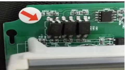
The mechanical stress applied to the coupler (vibration, impact, centrifugal force, installation stress, or other mechanical quantity) exceeds the specified maximum, resulting in irreversible changes in the optocoupler structure. The optical coupler is struck by external stress, causing the tube leg to fall off, as shown in Figure 2.
In addition, the temperature, humidity and salt fog will cause the optocoupler to fail. High temperature had a great influence on CTR, and with the increase of temperature, CTR began to decrease. Under normal circumstances, the CTR at 75℃ is only about 25℃ of 75%, while the low temperature has little influence on CTR. High temperature has a great influence on the positive current IF and power dissipation PCof optocoupler. With the increase of temperature, the forward
current IF and power dissipation PC begin to decrease. High temperature also affects collector to
emitter saturation voltage drop, VCE and collector dark current ID(CEO) and as the temperature rises,
both increase. High temperature and humidity mainly affect the pin and package of optocoupler, leading to the corrosion of pins or internal contamination of optocoupler.
[image:3.612.187.427.599.733.2]Parameter Detection Method
Firstly, check the status, processing quality and surface quality of the optocoupler. With a magnifying glass to observe the surface of the device, it is no dirt, there is no mechanical scratch. The detection characteristics of input and output parameters is relatively simple, in accordance with the provisions of the applied current and voltage monitoring and the corresponding current and voltage can be applied only for environmental parameters relative to environmental parameters, and can be monitored. In the warehouse of 20 manufacturers, 35 batches of photoelectric coupling are randomly selected, the time characteristic is unqualified and the ratio is 25%. Refer to GB/T 15651.3 - 2003 in the 5.7 method, use pulse signal generator, voltage source, oscilloscope and other equipment to test, generally require the amount of time should be less than 12us. During testing, the supply voltage Vc is applied to the output circuit which is coupled by photometry, and the pulse generated by the G1 loads the input of the optocoupler to increase the pulse amplitude until the specified output current is IC or IE. The time parameter is determined by the waveform observed on
the oscilloscope. The test condition is IC=2mA or IE=2mA, the supply voltage is Ucc=10V and
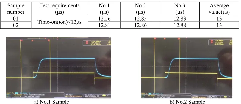
[image:4.612.105.510.338.513.2]input resistance 50Ω, and the load resistance 100Ω.The time characteristics of the opening time is input and output conversion ability of optocoupler performance, the unqualified data are taken only three time property does not meet the requirements of the optocoupler, the testing results are difficult to meet the requirements for the opening time, the specific data see table 1. The waveform curve of the test is shown in Figure 3.
Table 1. The test data of optocoupler time characteristic.
Sample
number Test requirements (μs) No.1 (μs) No.2 (μs) No.3 (μs) value(μs) Average
01 Time-on(ton)≤12μs 12.56 12.85 12.83 13
02 12.81 12.86 12.88 13
a) No.1 Sample b) No.2 Sample Figure 3. Opticalcoupler time characteristic test waveform.
Summary
Optocoupler is the main device of electrical isolation. It is widely used in smart meter, and the performance parameters should be considered in the design. This paper introduces the characteristics of the technical parameters of optocoupler, and analyzes its inherent failure causes and the main causes of the failure of various stress, which provides the basis for designers to select optocoupler. At the same time, it is pointed out that the time characteristic of optocoupler is the most important parameter, and a common detection method of optocoupler time characteristic is put forward, which provides reference for manufacturers to choose optocoupler with high cost performance.
References
[2] He Shengzong, Wu Huiwei, The Application of Failure Analysis in the Reliability Improvement of Smart Meter, Electronic Product Reliability and Environment testing, 34(2016)26-30.
[3] Yi Puzhi, Xu Renheng, Zhang Mingyu, etc, Design and implementation of the watt-hour meter reliability prediction system based on Cloud platform, Electrical Measurement & Instrumentation. 54(2017)96-100.
[4] Zhang Shengyan, Liu Xiaokang, Hu Shuixian, Discussion on Optocoupler’s Applicationm, Avionics technology. 46(2015)51-54.
[5] Liu Jiangpin, Xue Xiao, Liu Xiaoliang, Application and Analysis of Optoelectronic Isolated Components in Digital Output of Safety Instrument System, Instrumentation. 24(2017)45-47. [6] Wu Dongjian, Jiang Zhu, Wu Yonghong, etc, A Method of Temperature Separation Measurement with Linear Optocouplers, Journal of Astronautic Metrology and Measurement. 35(2015)30-32.
[7] Wen Youlu, Wan Youzhang, Guo Chao, Design of Optocoupler Isolated Differential Bus Transceiver Chip, Aircraft design. 37(2017)35-38.