2016 International Conference on Computer, Mechatronics and Electronic Engineering (CMEE 2016) ISBN: 978-1-60595-406-6
CRS-aided MMSE algorithm for LTE Downlink
Wen-qin XIAO and Zhi-song BIE
School of information and Communication Engineering, Beijng, University of Posts and Telecommunications, Beijing, China
Keywords: MMSE, LTE, CRS.
Abstract. MMSE algorithm has good performance in an ideal situation, but channel information is required. In order to improve the practicality of the MMSE algorithm, in this paper, a method that estimates channel information through CRS (Cell-specific Reference Signal) is proposed in LTE system. In the simulation, MMSE algorithm, ML algorithm and LS algorithm are compared in the LTE system under the same simulation conditions. Simulation results show that CRS-aided MMSE algorithm outperforms ML algorithm and LS algorithm.
Introduction
LTE system based on pilot-assisted channel estimation algorithm has been widely studied. There are many common channel estimation algorithms, such as MMSE (Minimum Mean Square error Estimation) [1], ML (Maximum Likelihood) [2] and LS (Least Square) [3]. LS algorithm is less complex, and its performance is close to MMSE algorithm when SNR is high. ML algorithm only needs to know the channel length. MMSE algorithm has good performance in ideal case, but it needs much channel information. To increase the practicality of the MMSE algorithm, a method that obtains channel information through CRS (Cell-specific Reference Signal) is proposed in this paper.
System Model
A physical resource block is defined as NsymDL consecutive OFDM symbols in the time domain and RB
sc
N consecutive subcarriers of frequency 15kHz each in the frequency domain. When normal cyclic prefix is used, we can know NsymDL 7 and NscRB 12. There are NsymDLNscRB resource elements in a physical resource block. Physical resource blocks are numbered from 0to NRBDL1 in the frequency domain [4].
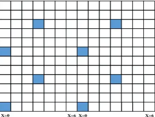
The Figure 1 shows one subframe with 12 subcarriers in each symbol. The shaded area is the position of subcarriers used for Cell-specific Reference Signal (CRS) for port zero and port one. The OFDM symbols with reference signal called as pilot data, are called as pilot symbols and the OFDM symbols consisting of only data subcarriers are called as data symbols. There are two pilots in a OFDM symbol in a resource block, so there is totally 2 DL
RB
N pilot in a OFDM symbol [5].
[image:1.595.218.378.632.752.2]X=0 X=6 X=0 X=6
Consider a LTE downlink OFDM system. It is assumed that the Mobile station (MS) is connected to a Base Station (BS), called the serving BS, and the serving BS transmits data to the desired MS. It is assumed that there are two send ports for Cell-specific reference signal in BS and there are two receiving antennas in MS. It can be seen as a 2 2 MIMO-OFDM system. Hence, there are 4 subchannels in the downlink channel. There are 14 OFDM symbols in a subframe. The MS received signal is given by:
1
1 1
0
( )
j ij i ij i
Y H X V
0 i 1,0 j 1
11
8 8
0
( )
j ij i ij i
Y H X V
0 i 1,0 j 1
2 Where Xi1 is the CRS transmitted signal vector in 1st OFDM symbol of a subframe in the ith port,2
i
X is the CRS transmitted signal vector in 8th OFDM symbol of a subframe in the ith port, Vij is the noise of the ith transmitting port to the jth receiving antenna. Yj1 is the received signal of the CRS position in 1st OFDM symbol in the jth receiving antenna. Yj8 is the received signal of the CRS position in 8th OFDM symbol in the jth receiving antenna. Hij is the channel vector of the ith transmitting port to the jth receiving antenna in an OFDM symbol. It can be considered that Hij is the same in a subframe. X1i,Xi8,Yj1,
8
j
Y ,Vij,Hij are 1 2 DL RB N
matrix.
It is assumed that ˆHij is the estimated value of Hij by LS algorithm. It can be rewritten as follow:
1 1
8 8 1 1
1 1
0 8 8 1 1 1 1
0 1 0 1
ˆ j j
j
Y X Y X
H
X X X X
3
1 1
8 8 1 1
0 0
1 8 8 1 1 1 1
1 0 1 0
ˆ j j
j
Y X Y X
H
X X X X
4 Where
k 1, 0,1; 1,8i
X i k is a 2 DL 2 DL RB RB
N N matrix and Xik
Xik 1 I
, where I is a 1 2 NRBDL matrix and all of its elements is 1, ˆHij is a 1 2
DL RB N
matrix.
MMSE algorithm needs much channel information, which includes the length of channel impulse response, the number of channel multipath, multipath position, the power of multipath and channel noise. This information will be obtained through ˆHij in next section.
A Method to Estimate Channel Information through CRS
It is assumed that the 1 2 NRBDL matrix hij is the Fourier transform of ˆHij. It can be rewritten as follow:
ˆ
( ), 0 1, 0 1 ij ij
h ifft H i j
ˆ H, 0 1, 0 1, 0 2 DL 1
ij ij k ij k RB
k
h h h i j k N
6 Where ijk h
is the kth element of hij; ij H k h
is the conjugate transpose of ij k h
; ˆij
k h
is the
kth element of ˆhij. ˆ
ij
h can be considered as the power vector of channel that is ith transmitting port to the jth receiving antenna. To estimate real power vector of channel impulse response, we need to superimpose four sub channels, which can be rewritten as follow:
1 1 0 0 ˆ power ij i j h h
7 Where hpower has different resolutions with the real channel power vector.In a real LTE system, the number of sampling points in an OFDM symbol is 2048 when the bandwidth is 20M. Hence, the points of real time - domain impulse response is 2048. The sampling interval in frequency domain is 15K. The length of channel impulse response can be rewritten as follow: 2048 1 15 t K
8 The usable subcarriers and virtual subcarriers is 2048, and the time interval between two adjacent points in real channel impulse response is calculated as follow:2048 2048 2048 t t
9 The interval between the adjacent CRS is 6 subcarriers .And there are 2NRBDL pilots in an OFDM symbol. It can be considered that there are 12 DL 5RB
N subcarriers between the first pilot and the last pilot. So the interval between two adjacent points in hpower is calculated as follow:
2048 2 (12 5) RB N DL RB t t N
10 The cyclic prefix of the 20M LTE system is given by CP2048 144. It can be considered that there is no multipath over theCP2048 in real channel impulse response. Hence, the corresponding cyclic prefix of hpowercan be rewritten as follow:2048 2048 2 2 RB RB N N CP t CP t
11 It can be considered that there is no multipath over the 2RB
N
CP in hpower.According to actual condition, we can consider that 16 multipath can express real multipath channel. Hence, we consider that the 16 positions of the largest 16 points before 2
RB
N
CP in hpoweris the corresponding multipath position, the corresponding multipath position can be rewritten as follow:
1 2 16
ˆ ˆ ˆ, ,...,ˆ position
P p p p
12 Where pˆi pˆ .1i1 i 15.
1 2 16
2
2048
, ,....,
ˆ ,1 16
RB
position N
i i
P p p p
t
p p i
t
13Where ˆpi is the ith element of ˆPposition. is the symbol to round numbers.
Then we can get the power of each multipath through
12 . The power of multipath can be rewritten as follow:
1 2 16
ˆ
, ,...,
,1 16
i
power
i power p
P P P P
P h i
14 Where ˆi
power p
h
is the ˆpith element of hpower, ˆpi is the ith element of ˆPposition.
The last channel information that is used in MMSE algorithms is the channel noise. We can estimate that through ˆhij in
6 . According to
11 , it can be considered that signal energy exists before 2RB
N
CP in the time domain, and taking energy leakage into account, signal energy also exists
after 2 DL RB N
in the time domain. With the consideration of boundary problem, it is assumed that the
points between 1 2 1
10 RB Dl RB N N n CP
and 2
3 2
DL RB N n
in ˆhij are pure noise. So we can estimate
the sub channel’s noise through the average energy of these points. It is assumed that Nij is the pure noise section in ˆhij, which is a 1
n2 n1 1
matrix. It can be rewritten as follow:1 1 1 2
ˆ , ˆ ,..., ˆ
ij ij ij ij
n n n
N h h h
15 Then we can get all the subchannel’s noise as follow:2 1
2
, 0 1, 0 1 1
H DL
ij ij RB ij
N N N
noise i j
n n
16Finally, the real noise can be rewritten as follow:
1 1 0 0 4 ij i j noise Noise
17In this section, we get all the channel information we need in the MMSE algorithm.
Simulation Results
Table 1. LTE simulation parameters for comparison of channel estimation algorithms.
Parameters Capacity
Slot duration 0.5[ms] Sampling Frequency 30.72[MHz]
Carrier Frequency 2.3[GHz] Subcarrier spacing 15[kHz]
Channel Environments SCME 3GPP UMANLOS1
Layer Number 1
MCS Level 5
Modulation QPSK
Transmission mode TM8
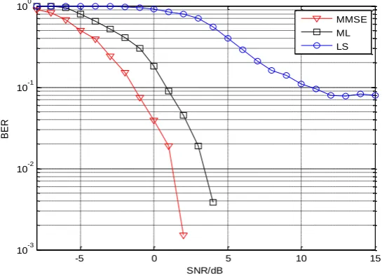
Figure 2 shows the comparison of LS, ML and MMSE estimation algorithms for different SNR. It is obvious that MMSE algorithm outperforms all the other algorithms. ML algorithm is slightly inferior to MMSE algorithm and outperforms the LS algorithm. LS algorithm cannot reduce the BER obviously with the increase of SNR at high SNR. As for complexity, MMSE and ML algorithm are similar. MMSE and ML algorithm are more complicated than LS algorithm.
-5 0 5 10 15 10-3
10-2 10-1 100
SNR/dB
BER
MMSE ML LS
Figure 2. BER vs SNR for various estimation algorithms.
Conclusion
In this paper, we bring forward a method to estimate the channel information that MMSE algorithm needs through CRS. Then we compare the performance of CRS-aided MMSE algorithm, ML algorithm and LS algorithm. MMSE algorithm outperforms all the other algorithms with the similar complexity to ML algorithm. LS algorithm performs not well in bad channel environment, although its complexity is the lowest. Finally, the simulation results prove the rightness of the method, which increases the practicality of MMSE algorithm in LTE system.
References
[1] H. Senol, H. Cirpan and E. Panayirci. MMSE Estimation Approach for Karhumen-Loeve Expansion Coefficients of Multipath Channel in OFDM. 2003.
[3] J.J. VandeBeek, M. Salldell etc. On Channel Estimation in OFDM Systems [J]. Proc. IEEE. Vehic. Technol. Conf, July 1995 (2):815-819.
[4] 3GPP TS 36.211 V8.4.0(2008-09). Evolved Universal Terrestrial Radio A Physical Channels and Modulation, (Release 8).