2017 International Conference on Mathematics, Modelling and Simulation Technologies and Applications (MMSTA 2017) ISBN: 978-1-60595-530-8
CFD Simulation of Internal Solitary Wave Using the Volume-of-fluid
Method within OpenFOAM
Li ZOU
1,2,*, You YU
1, Zhe SUN
1, Jiu-ming ZHANG
1, Zhen-hao LI
1and
Zong-bing YU
11School of Naval Architecture, State Key Laboratory of Structural Analysis for Industrial Equipment,
Dalian University of Technology, Dalian 116024, PR China
2Collaborative Innovation Center for Advanced Ship and Deep-Sea Exploration, Shanghai 200240,
PR China *Corresponding author
Keywords: Internal Solitary Wave, VOF, Numerical wave tank.
Abstract. A numerical wave tank based on OpenFOAM was developed to investigate internal solitary waves. The interface of fluids was captured by VOF method. In this paper, comparisons between numerical results and different theoretical solutions were made to evaluate the performance of the numerical wave tank. The result shows that it is a feasible way to further explore the behavior of internal solitary waves by numerical wave tank based on OpenFOAM.
Introduction
Internal waves (IWs) exist at the interface of the density stratified ocean. As a kind of IWs, an internal solitary wave (ISW) usually has a significant leading waveform with minor trailing oscillations [1]. A large ISW often causes strong shear flow which can affect the safety of offshore structures. For example, an ISW once observed in the South China Sea had an amplitude of 170m with the velocity difference exceeding 3.4m/s between the upper and lower layer [2]. Therefore, it is of great importance to study the behavior (e.g. generation, propagation, dissipation) of ISWs.
Over the past several decades, many researchers have conducted laboratory experiments and numerical studies to investigate the behavior of ISWs. Kao et al. [3] investigated experimentally the evolution and breaking of an ISW as it propagated to a shallower shelf region. In their experiment, the gravity collapse method was first used to generate an ISW. Wessels and Hutter [4] studied the propagation of ISWs in the wave channel by double-piston wave-making method. Chen et al. [5] simulated the propagation of IWs over various topographies in ANSYS Fluent. Zhu et al. [6] developed a numerical internal wave tank by immersed boundary method and the wave profile agreed well with the analytic solution.
OpenFOAM (for "Open source Field Operation And Manipulation") is a C++ toolbox for the development of customized numerical solvers including computational fluid dynamics (CFD), which has been used for a wide range of applications in recent years. Lambert [7] developed a numerical wave tank using OpenFOAM and the simulation was shown to be able to replicate the experimental values within a good degree of accuracy. Davidson et al. [8] conducted wave energy experiments by implementation of an OpenFOAM numerical wave tank. Therefore, it is a feasible way to investigate the behavior of ISWs using OpenFOAM.
To investigate the behavior of ISWs, a numerical wave tank based on OpenFOAM was developed in this paper. The gravity collapse method was used to generate an ISW and the profile of ISWs obtained by the volume of fluid (VOF) method was compared with theoretical solutions.
Theoretical Background of ISWs in a Two-Layer Fluid System
The governing equation of ISWs is based on the assumption that the fluid is inviscid and incompressible, the flow is potential, and the rigid-lid hypothesis is employed for the free surface.
The dispersion parameter is defined as:
,
h
(1) where h is the total depth of the fluid, is the characteristic wavelength of the internal wave.
When1, the MCC solution of the internal wave under the stationary state can be obtained [10] as:
2
2 1 1 2
2 2
1 1 2 2 3
3 ( ) ( )( ).
( )
g a a
x c h h a
(2) For the parameters in the above equation, is the interface elevation, a is the amplitude, i andhi
are the density and thickness of the upper or lower fluid respectively.
2 1 2
2 1 2 0
( )( )
( / )
h a h a c
h h c g a
,
2 1 2 2 1 0
1 2 2 1
( ) , gh h c h h
(3)
1
a ,a2 are the solutions of the equation:
2 2 2
2 1 2 0
2
1 2 0
( )
0,
h h c c c
g h h c
(4)
1 2 1 1 2 2
3 2 2
1 1 2 2
( )
.
h h h h a h h
(5)
According to above equations, the MCC solution of the interface can be computed.
When the nonlinear parameter
a h/ 1 , the equations can be simplified to KdV equation [10]:0 1 2 0,
t c t c X c XXX
(6) where
2 2 2 2
0 1 2 2 1 0 1 2 1 2 1 2
1 2 2 2
1 1 2 2 2 1 1 2 2 1
3 ( ) , ( ).
2( ) 6( )
c h h c h h h h
c c
h h h h h h
(7)
The solution of the KdV equation is
2 1 1
0 2
sech ( ) , , .
12 3
KdV KdV KdV KdV
ac ac
a x c t c c
c
(8)When considering the item with the order of ( )2
O , the equation changes to eKdV equation [11]:
2
0 1 3 2 0.
t c c c X c XXX
32
1 3
1 3 1 3
0
2
, ,
(1 ) cosh ( ) 2
( 1/ 2 ) ( 1/ 2 )
, . 3 12 eKdV eKdV eKdV eKdV ac a B
B B x c t c ac
a c c a a c c a
c c c (10)
When h h1/ 2 1/ 2 , c10in KdV equation, the above modeling is no longer applicable.
Under this condition, the mKdV equation was proposed [12]:
2 2
sech ( )
,
1 tanh ( )
mKdV mKdV
mKdV mKdV
a x c t
x c t
(11) where two situations h2hc and h2hc are considered, and hc is the critical thickness:
1 2 . 1 / c h h
(12)
In this paper, the KdV, eKdV and mKdV equations were employed as the reference values to compare with the numerical results.
Numerical Method
Governing Equation
This research is conducted using OpenFOAM 3.0.0. The 2D Navier-Stokes equation and the continuity equation are solved. The continuity equation is
0,
u w x z
(13)
and the Navier-Stokes equation of 2D incompressible flow can be written as
2 2 2 2 2 2 2 2 1 , 1 ,
u u u P u u
u w
t x z x x z
w w w P w w
u w g
t x z z x z
(14)where t is time, u andw are the velocity components in the x and z directions, P is the pressure, is the fluid density, and is the dynamic viscous coefficient.
The VOF method [13] is used to trace and locate the instant air-liquid and the interface between two liquid layers. In brief, the following equation is used:
0, q q v t
(15)
where v( ( , ), ( , ))u x z w x z and q is a fraction function used to define and calculate the volume ratio
of q-phase fluid in the computational mesh.
Model Setup
An ISW is generated using the gravity collapse method [3]. The size of the numerical wave tank is set asL5m,H 0.35m. The number of grids is 250 80 inxandzdirections, respectively. The left
system (air-silicone oil-water) is set and the schematic diagram of the wave tank and the properties of fluids are shown in Fig.1. h0,1,2is the layer thickness, 0,1,2means the density and
0,1,2represents thekinematic viscosity. The collapse area is set asx0.33mand d 0.05 , 0.07 , 0.09m m m in Case1, 2
[image:4.612.99.508.132.224.2]and 3 respectively.
Figure 1. Schematic diagram of the numerical internal wave tank.
Results
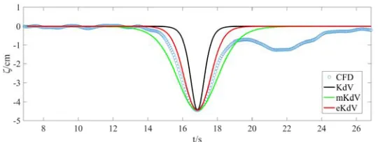
[image:4.612.170.439.318.418.2]The wave profiles of three simulation cases are extracted at the middle of the numerical wave tank, where the waveform is stable. As shown in Fig 2-4, wave profiles are compared with the solutions of KdV, mKdV and eKdV.
Figure 2. Wave profile comparison between Case1 and theoretical solutions.
Figure 3. Wave profile comparison between Case2 and theoretical solutions.
Figure 4. Wave profile comparison between Case3 and theoretical solutions.
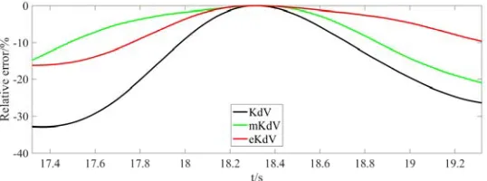
[image:4.612.171.440.448.546.2] [image:4.612.171.441.573.675.2]corresponding to the three cases in Fig. 2-4 are shown in Fig. 5-7. Table 1 lists the mean relative error between the numerical waveform of three cases and theoretical solutions.
Figure 5. Relative errors between Case1 and theoretical solutions.
Figure 6. Relative errors between Case2 and theoretical solutions.
[image:5.612.170.439.98.198.2]Figure 7. Relative errors between Case3 and theoretical solutions.
Table 1. Mean relative error.
Case
Number KdV Mean relative error[%] eKdV mKdV
1 -15.68 -5.94 -7.16
2 -23.60 -6.32 -7.20
3 -32.26 -5.58 -5.46
For eKdV and mKdV solutions, the mean relative error is less than 8% in all three cases, whereas the KdV solution shows a relatively great deviation and the mean relative error becomes greater with the increase of amplitude of ISWs. It can be seen that both eKdV and mKdV solutions agree well with the simulation results.
Summary
[image:5.612.101.510.500.571.2]OpenFOAM, which can be further applied to the study of the ISWs behavior and its interaction with offshore structures.
Acknowledgements
The present work is supported by the National Natural Science Foundation of China (51522902, 51379033,51579040), the Fundamental Research Funds for the Central Universities (DUT17ZD233).
References
[1] Hsieh, C.M., Hwang, R.R., Hsu, R.C., and Cheng, M.H., Numerical modeling of flow evolution for an internal solitary wave propagating over a submerged ridge, Wave Motion, 55 (2015) 48-72. [2] Klymak, J.M., Pinkel, R., Liu, C., Liu, A.K., and David, L., Prototypical solitons in the South China Sea, Geophysical Research Letters, 35 (2006).
[3] Kao T.W., Pan F.S., Renouard D, Internal solitons on the pycnocline: generation, propagation, and shoaling and breaking over a slope, Journal of Fluid Mechanics, 159 (1985) 19-53.
[4] Wessels F., Hutter K., Interaction of Internal Waves with a Topographic Sill in a Two-Layered Fluid, Journal of Physical Oceanography, 26 (1996) 5-20.
[5] Chen, B.F., Huang, Y.J., Chen, B., and Tsai, S.Y., Surface wave disturbance during internal wave propagation over various types of sea bottoms, Ocean Engineering, 125 (2016) 214-225. [6] Zhu, H., Wang, L.L., Avital, E. J., Tang, H.W., and Williams, J.J.R., Numerical Simulation of Shoaling Broad-Crested Internal Solitary Waves, Journal of Hydraulic Engineering, 143 (2017) 04017006.
[7] Lambert R.J. Development of a Numerical Wave Tank Using OpenFoam, (2012).
[8] Davidson, J., Cathelain, M., Guillemet, L., Huec, T.L., and Ringwood, J.V., Implementation of an OpenFOAM Numerical Wave Tank for Wave Energy Experiments, European Wave and Tidal Energy Conference, (2015).
[9] Huang W.H., You Y.X., Wang X., Hu T.Q., Wave-making experiments and theoretical models for internal solitary waves in a two-layer fluid of finite depth (In Chinese), Acta Phys. Sin.,62 (2013) 354-367.
[10] Choi W., Camassa R., Weakly nonlinear internal waves in a two-fluid system, Journal of Fluid Mechanics, 396 (1999) 1-36.
[11] Helfrich K.R., Melville W.K., Long nonlinear internal waves, Annual Review of Fluid Mechanics, 38 (2006) 395-425.
[12] Michallet H., Barthélemy E. Experimental study of interfacial solitary waves, Journal of Fluid Mechanics, 366 (2000) 159-177.
[13] Hirt C.W., Nichols B.D., Volume of fluid (VOF) method for the dynamics of free boundaries, Journal of Computational Physics, 39 (1981) 201-225