IBM
®Programming the IBM 1440 Data Processing System
c
Preface
This book is written for the student who has had some exposure to data processing systems and who is inter-ested in learning to program and operate the IBM
1440 Data Processing System. It is assumed he has some knowledge of computers and programming acquired either by having satisfactorily completed the IBM Basic Computer Systems course or an equivalent course; or through actual but limited experience in programming. Before studying the material in this book, the student should know the meaning of terms such as: actual codes, symbolic codes, input, output, core storage, ad-dress modification, indexing, compiler, block diagram-ming, source program, object program, record layout, binary-coded decimal- terms defined in the Basic Com-puter Systems course.
The present book contains Part 1 which through the generous use of examples covers most aspects of pro-gramming the 1440 Data Processing System. It is in-tended as a supplement to classroom instruction in the IBM 1440 Basic Programming Course and its contents therefore closely parallels subjects covered in the 1440 course.
Chiefly, these subjects are the Autocoder (pro-grammer's) language, the techniques of programming, and the system in general. The book will be repub-lished in the future to include Part 2 which will
explain those details one must know to operate the computer and to test one's program.
Questions to test comprehension follow each section. Answers to the questions will be found in the Appendix at the back of the book. The student's ability to com-plete these test questions indicates readiness to proceed to the next section. Upon successfully completing Part 1, the student will be able to write his own programs for the 1440 in Autocoder language.
Each section in this book builds upon the previous section. Therefore the student will find it to his advan-tage to study the material and to complete the exercises in the order presented. Students with considerable pro-gramming experience on other systems may wish to re-view the questions and problems to determine at which point they will begin their study.
The programming examples represent the author's solutions to the problems. The student may find solu-tions that differ from the author's. This is possible, for seldom is there only one acceptable solution. Look
upon the author's solutions simply as a guide. Additional reference material covering the subjects described in this book may be found in the Systems Reference Library for the IBM 1440 Data Processing
System and in the IBM 1440 A utocoder (Preliminary Specifications) Systems Bulletin.
o
(,
c
Preface " " " " " " " " " " " " " " " " " " " " " " " ' " 2
Section 1 " " " " " " " " " " " " " , . , " " , . " .. " .. , .. " 5 Components of the 1440 Data Processing System. , , , , , ... " 5
IBM 1441 Processing Unit. .. , . , , , , . , , , , , . , , , , , .. , , . , , .. , 5
IBM 1442 Card Read-Punch. , ... , . , , .... , , . , , .. , , , , , , , .. 6
IBM 1443 Printer. , , ... , , , ... , , , . , , .. , ... , .... , , .. , " 7
IBM 1311 Disk Storage Drive., .... " ... "., .. ,"','," 8
IBM 1447 Console, .. , , ... , , , , .. , . , ... , ... , , , , . ' , , , . , , , , , 10 Review: Questions, , , , . , , , , .... , , . , . , . , , . , , , , . , , , , , . , . , , ,14
Section 2 . , . , . , , . , , . , .... , . , , , .. , . , , , . , .. , , , , . , , , , , , , , , , ,15 Introduction to Programming ... , ... , , , .. , , . , , , .. , , ... , . , ,15 Purpose of Programming, ... , , . , , . , , , . , .. , . , . , , , .. , ... ,IS Function of the Programmer, . , . , , . , , , . , , , .. , ... , , , , . ,IS Language of Programming. , , . , ... , . , , , , , . , ' , .. , , , . , . 15 Use of Autocoder Coding Sheets .. , ... " . , " , . , ... ,',.,' ,17 Symbolic Assignment of Core Storage, , , , , .. , , . , , . , .. , , , ,20 Review: Questions , , .... , . , , .. , , , , ... , .. , , , , . , ... , ... , .. ,22
Section 3 .. , , , , , , . , . , , .. , . , .. , ... , , .. , .... , ... , .. , , . , .23 Programming a Basic Job .. , . , ... , ... , , .... , ... ,23 Arithmetic Sign Control and Overflow .. , , . , ... , .. , ... ,26 Review: Questions , . , . , , .... , , , , , . , . , , , .. , . , , , . , , , .. , , , , ,27
Section 4 ' , , , , , , , . , .. , . , , . , , , . , , . , . , , , , , . , . , . , , , ... , .. ,28 Programming the Card System .. , , , , . , , .. , , , , .. , .. , ... , , , ,28
Contents
Programming Example 1:
Detail Printing from Cards ... , . , , .... , ... , .. , .. , , .28 Programming Example 2:
Detail Printing with Three Classes of Totals. , ... , , . , .. , , .35 Programming Example 3:
Reading/Punching and Multiplication by
Repetitive Addition .,., ... , ... , .. , . .42 Programming Example 4:
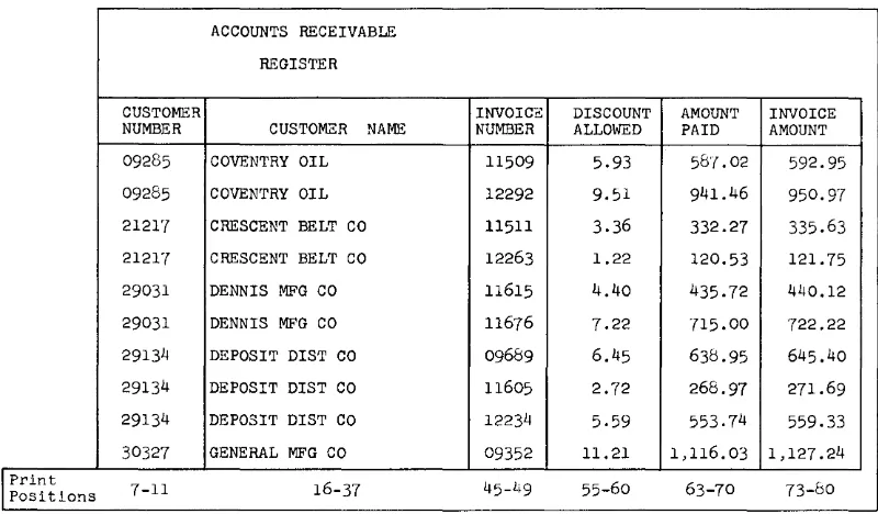
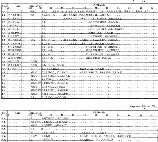
Multiple-Field Crossfooting with Control Register. , , ... , . ,45 Review: Questions , ... , , . , . , , .... , , , ... , .... , , . ,48
Section 5 '" ,., ,.' ,.,",.,.,.",' ,.,.,' ", ,." .. ,., ... ,. ,50 Programming with Disk Storage, , , .. , . , ... , , ... , .. , .. , .. 50 1311 Disk Storage Operations, , . , , , .. , .. , . , , , ... , ... , , ,51 Disk Check Indicators .... , ... , , .... , ... , . , .. , , ,54 Programming Example 5:
Storing Records in Disk Storage. , .. , , , . , . , , .. , .. , . , . , . , ,56 Programming Example 6:
Printing Name and Address Labels from Disk Storage.", ,57 Review: Questions , , , , , , . , , , , , . , . , , .. , .. , , , , , ... , . , ... , . ,62
Appendix: Answers and Solutions to Review Questions for
o
(~
Figure 1. IBM 1440 Data Processing System
© 1962 by International Business Machines Corporation
o
c
c
Programming the IBM 1440 Data Processing System
Section J
Components of
the
J440 Data Processing
System
Before directing our attention to programming the IBM 1440 System, we will describe the 1440 components, the characteristics of core storage, and the capabilities and capacities of the system. This background is essential to learning to program the system.
Every data processing system has various compo-nents. These are classified as input devices, output vices, and combination input/output or processing de-vices. The data to be processed by the system is known as input because it is entered into the system through an input device. The data already processed leaves the system through an output device and therefore is known as output.
In the 1440 System, input and output data can be in typewritten form, or in the form of punched cards or magnetized spots on disks. Output in the form of a printed report is further possible.
Processing in the 1440 is performed by the IBM 1441 Processing Unit. The 1440 combination input/output devices are the IBM 1442 Card Read-Punch, the IBM 1311 Disk Storage Drive, and the IBM 1447 Console. The IBM 1443 Printer is an output device only. Figure 1 shows the complete system. To understand the func-tions of the components and the part they play in the complete data processing operation, let us examine each unit individually.
1441 Processing Unit. The 1441 provides the
pro-grammer with control over the other components of the
system. It contains the logic as described by its stored program and sufficient storage to perform its functions
among which are the arithmetic operations. In
sum-mary, then, the three functions of the 1441 unit are: (1) Control, (2) Storage, and (3) Arithmetic.
1442 Card Read-Punch. The 1442 provides the
sys-tem with input from punched cards and output in the same form.
1443 Printer. The 1443 is used to print high-volume
output.
1311 Disk Storage Drive. The 1311 utilizes disk packs
to provide storage for large amounts of output. The output stored in the disk packs becomes input to the system.
1447 Console. The 1447 provides external control
over the 1440 Data Processing System. It can be equipped with a typewriter for keyboard input to the system and also for use as a low-volume output printer. The relationship of the 1441 Processing Unit to the other components of the system is shown in Figure 2. The arrows in the figure indicate the direction in which data moves from component to component, as directed by the processing unit. They show that:
1. Data can be read from the card in the read-punch into the processing unit. From this unit the data can be moved as output to disk storage, or to the printer, or to the console printer, or to the card read-punch, or to any combination of these, as required
2. Input data from disk storage can be read into the processing unit and moved from there as output
to the printer, or to the console I/O printer, or
to the card read-punch, or to disk storage, or to any combination of these, as required
3. Input data keyed in at the typewriter can be read into the processing unit and moved from there as output to the card read-punch, or to disk storage, or to the printer, or to the console I/O printer, or to any combination of these, as required.
IBM
J44J
Processing Unit
The IBM 1441 Processing U ni t has provision for from 4,000 to 16,000 positions of core storage, in increments of 4,000. Each position is capable of storing an alpha-betic, numerical, or special character. Characters are coded in binary-coded-decimal form. When we discuss core storage in a later section, we will have more to say about BCD coding.
1442 Card Read - Punch
"!'ORT
....
_
...erdIIMIjJcmJdhgdllnrt
dfgflnni'*'kopDr;Jf ,...._hkbeb&bll cl..t'b:4catNb_kow DOalarlUllklwolmap
NgCWldOfbluNgtg!1
q1nftdabDfwmhfgkj
...-mmfnlDJUCm
""'
...
-1447 Console Madel 2
Figure 2. Flow of Data through 1440 System
Each position of core storage is addressable; that is, may be addressed by a program instruction. The data in the location addressed may be used by the computer in performing an arithmetic operation or may be moved to or from the addressed location. Variable length fields as in the 1440 allow greater use and flexi-bility in storing data and these variable fields can be handled by most program instructions. The program
1443 Printer
instructions are stored within the unit to perform the operations of input/output, arithmetic, and logic.
IBM 1442 Card Read-Punch
Card reading and punching functions are provided in one unit and have a single card path. The cards are read or punched, proceeding serially from column 1 to
o
c
c
column 80. This diagram shows the path of the card through the read-punch.
Capacity 1200
Stacker 2 (Optional
on M:>del 1) Note: Stacker Capacity
1300 Cards
The card must pass the reading station before it can be
punched. Cards are read at the reading station - col-umn by colcol-umn - by means of a solar sensing unit, con-sisting of twelve solar cells, one for each punch position in a card column.
Solar Cells
As each column is read, the character is converted from card code to its binary-coded-decimal representation and is stored in core storage. Any area in core storage may be used to store the card data as determined by a stored program instruction.
The 1442 Card Read-Punch is available in two models: Model 1 is equipped with one card stacker and Model 2 with two card stackers to allow card selec-tion. The second stacker is available with the Modell as a special feature. A comparison of the card reading and punching speeds for the two models is shown in
the following table.
Operation Modell Model 2
Reading only 300 cpm 400 cpm
Reading and then: Punching first 10
columns 180 cpm 270 cpm
Punching first 20
columns 130 cpm 210 cpm
Punching first 30
columns 103 cpm 172 cpm
Punching firs t 40
columns 84 cpm 146 cpm
Punching first 50
columns 62 cpm 112 cpm
Punching first 80
columns 50 cpm 91 cpm
At these card speeds, a minimum of 75 milliseconds of calculating time is allowed for the Model 1 between the reading and punching of each card, and 55 milli-seconds for the Model 2.
Two 1442 Card Read-Punches can be attached to the system. This configuration allows the card reading function and card punching function to be performed on separate units, thus providing additional flexibility as the application requires.
IBM
J 443 PrinterA single, stored program instruction can cause up to 120 positions of core storage to be read out of storage and printed. Therefore, the instruction or instructions to assemble a complete line of printing within an area in storage should precede the print instruction.
The standard character set for the printer comprises 52 characters, each printable in all 120 printing posi-tions. Two different 52 character sets, designated Type Fonts A and H, are available. A listing of the special characters associated with Type Fonts A and H follows:
16 Special Characters
Card 12 12 12 11 11 11 0 0 0 12 11 0
Codes 3 4 3 4 3 4 3 4 0 0 2 2 5
8 8 8 8 8 8 8 8 8 8 8
Type Font A &
n
$*
<.70/
# @ ?=t
0Type Font H
+
) $*
(/
?=t
0Each has the 26 letters of the alphabet, the 10 num-erals, and 16 special characters.
NOTE: The numbers at the head of each column are the card codes for the special characters.
Type Font A mounted on a single type bar is the standard character set. The type bar is operator inter-changeable, i.e., the operator can remove a type bar of a particular font and replace it with a type bar of a different font.
A character set is repeated several times on a type bar. During printing, the type bar travels on a hori-zontal plane. When the character on the type bar matches the character desired in the print position, printing occurs. All positions are printed in this man-ner.
The rated speed of a Model I printer equipped with the 52-character set is 150 lines per minute. This speed includes a period of 24 milliseconds for calculating time.
In addition to the 52-character set, a 63-character set, a 39-character set, and a 13-character set are available as special features. These sets also are operator inter-changeable. Their rated printing speeds are:
Set 13 character 39 character 63 character
Model I (lines per
minute) 430 190 120
At these speeds, 24 milliseconds is allowed for calcu-lating.
In addition to the 120-position printing line, a 144-position printing line is available.
Normally, each application prescribes its own format for printing a form. To position a form in its prescribed format, a separate tape must be prepared. This tape, working in conjunction with the stored program, con-trols the carriage that positions the form for printing.
IBM
1311Disk
StorageDrive
As many as five disk storage drives are available to the 1440 Data Processing System. On these drives can be mounted individual disk packs with a storage capacity of 2,000,000 alphameric characters per disk. In this way there can be made available to the system, con-tinually and at anyone time, a total of 10,000,000
8
characters of data. The disk packs can be removed by the operator and replaced with others, in effect provid-ing the system with unlimited storage.
Another feature of the disk packs is their interchange-ability. A disk pack from one disk drive can be inter-changed with one from another disk drive, either in that same system or in another 1440 system.
The replaceable disk pack offers both unlimited se-quential storage and random storage. Records for a particular application can be stored sequentially or randomly or both randomly and sequentially. Retrieval in either manner is also possible. Random records can be retrieved sequentially or sequential records can be retrieved randomly. However, the latter method re-quires that the programmer provide a table lookup.
The disk pack weighs approximately ten pounds and consists of six 14-inch disks. Each disk surface with the exception of the upper surface of the top disk and the lower surface of the bottom disk is used as a re-cording surface. Therefore, ten readable surfaces are provided by a disk pack.
Mounted vertically on a disk drive is a comb-type access assembly with five access arms on each of which there are two read-write heads. The access assembly is used to position the read-write heads on the disk sur-faces (Figure 3) . Each of the access arms, with its two read-write heads, moves between the bottom surface of a disk and the top surface of the next lower disk, and is capable of reading or writing data on both of these surfaces.
o
c
100 Cylinders
As the disk revolves, a read-write head passes over a circular band on the surface of the disk - this is called a track. The ten tracks that are exposed simul-taneously to the ten read-write heads as the disk pack
00 Cylinders
Figure 3. Read-Write Heads Positioned at one of the 100 Cylinders
revolves are referred to as a cylinder~ because of their cylindrical appearance when represented as in the il-lustration. A cylinder, in this sense, is a quantitative concept rather than a physical component. It may be considered to be a three-dimensional entity compris-ing a particular track on each of the ten disk surfaces. There are 100 cylinders, numbered 00 to 99, in a disk pack (Figure 3). The read-write heads can be posi-tioned at anyone of these 100 cylinders.
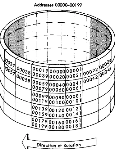
Each track is divided into 20 equal-size sections known as sectors. Every sector contains a 5-digit address and provides storage for either 90 characters of data with word marks or 100 characters of data without word marks.
All sectors are addressable. Therefore a disk pack provides 20,000 addresses that may be accessed for read-ing or writread-ing of data. This figure is arrived at in the following way:
20 addresses X 10 tracks = 200 addresses
per track per cy linder per cylinder 200 addresses X 100 cylinders = 20,000 addresses
per cyl- per
inder disk pack
99
The 5-digit sector address which precedes each sector in a disk pack is called the disk sector address. The
sector addresses are in numerical sequence within the track, cylinder, and disk pack. Figure 4 shows the layout of sector addresses for each track of cylinder 00' on the number 0' disk drive. The sector-address ranges for the five disk drives are:
Disk Drive Number
0' 1
2
3 4
Address Range 0'0'0'0'0'-19999 20'0'0'0'-39999 40'00'0'-59999 60'0'0'0-79999 80'0'0'0'-99999
The average time required to seek a sector address is 250' milliseconds; the maximum time, 40'0' millisec-onds. A seek is the operation of positioning the read-write heads (access assembly) at a specific cylinder on a disk drive. For each seek, the access assembly must first retract to its home position (outside cylinder DO')
and then move to the selected cylinder. A Direct Seek (special feature) is available which eliminates the return-to-home motion of the access assembly, thus reducing access time. With this special feature, the average access time is 150' milliseconds; the maximum time, 250' milliseconds.
Addresses 00000-00 199
Direction of Rotation
Figure 4. Layout of Sector Addresses by Track for Cylinder 00
IBM
J
447
Console
The 1447 Console is offered in two models: the Modell is equipped with keys, lights, and switches only. The panel on this console allows the operator to:
1. Start and stop the computer.
2. Initiate the loading of a program into core storage. 3. Display data from core storage.
4. Restart the program after an error condition has caused it to stop ..
5. Alter instructions in core storage.
The operation of the keys, lights, and switches on the 1440' will be covered in Part 2 of this book.
The Model 2 has, in addition, a Console I/0 Printer. The printer provided by this feature can be used to enter data into core storage and to type out data from core storage. In addition, the operator can use the printer to initiate an inquiry, that is, to request that a certain disk record be printed. Because inquiries are under control of the stored program, the programmer must provide the inquiry test instructions and sub-routines necessary to get the record.
Any of the 63 characters that are permissible in core storage can be printed out by the Console I/0 Printer. Its character rate is 14.8 characters per second. Nor-mally, this printer is used to type error messages, ex-ception notices, or inquiries.
Core Storage
In describing the 1441 Processing Unit, we mentioned that the 1441 uses core storage to store data and instruc-tions. At this point, we will describe some character-istics of core storage such as coding, organization, and the addressing scheme, for a knowledge of these char-acteristics will strengthen the programmer's foundation.
Character Coding
Characters are represented in core storage in binary-coded-decimal form. Each character is composed of a unique combination of binary digits, or bits as they
are called; one character to one position in core stor-age. A position in core storage has a 7-bit structure, which is designated CBA 8421.
The four rightmost bits (8421) are called numerical bits, because they correspond in a way to the numerical punches in card coding. Similarly, the BA bits corre-spond to the zone punches in card coding and are called zone bits. The C bit is the check bit that is generated within the system to give each character an odd or even count of bits, depending on whether the system uses odd or even pari ty.
The 1440' system uses an odd number of bits and the parity check consists of checking for this odd con-figuration of bits. It is an internal self-checking device
[image:10.620.43.228.468.708.2]c
c
o
of the computer for providing it with a high degree of assurance that it is operating correctly.
Table I shows the card codes and corresponding binary-coded-decimal form of the 64 characters (this includes a blank character) that can be entered into core storage. Note that the letters A-I have zone bits AB, corresponding in a way to zone punch 12. Simi-larly, the letters J-R have zone bit B, corresponding to zone punch II. The letters S-Z have zone bit A, corre-sponding to zone punch
o.
The numbers 0-9 are repre-sented by the numerical bits, 8-4-2-1, alone.In addition to the seven bits which we have discussed, there is an eighth bit, called the word mark (WM) , that is associated with each position of core storage. This bit defines the leftmost position of a data field and the first position of an instruction. Usually, the word
mark is placed in the leftmost position of a data field. When it is present in a position of storage, the bit combination in that position is adjusted to maintain an odd number of bits. For example, the letter A, when
a word mark
{lX}
is present, appears as: C BA WM
or when the word mark is absent, as: BA I
The bit configuration of each character shown in Table I is adjusted in the same manner. Zone bits or numerical bits of a character do not change: the con-figuration of the character changes only with respect to the C bit, which is either added or not added.
Table 1. Character Codes in Ascending Sequential Order
Defined Character Card Binary Code Defi ned Character Card Binary Code
Code C B A 8 4 2 1 Code C B A 8 4 2 1
Blank C G 12,7 B A 4 2 1
Period 12,3,8 B A 8 2 I H 12,8 B A 8
):! Lozenge 12,4,8 C B A 8 4 I 12,9 C B A 8 1
[ Left Bracket 12,5,8 B A 8 4 1 ! Minus-Zero 11,0 B 8 2
< Less Than 12,6,8 B A 8 4 2 J 11,1 C B 1
$ Group Mark 12,7,8 C B A 8 4 2 1 K 11,2 C B 2
& Ampersand 12 C B A L 11,3 B 2 1
$ Dollar Sign 11,3,8 C B 8 2 1 M 11,4 C B 4
* Asterisk 11,4,8 B 8 4 N 11,5 B 4 1
J Right Bracket 11,5,8 C B 8 4 1 0 11,6 B 4 2
; Semicolon 11,6,8 C B 8 4 2 P 11,7 C BI 4 2 1
I:l. Delta 11,7,8 B 8 4 2 1 Q 11,8 C B 8
-
Minus Sign 11 B R 11,9 B 8 1~ Diagonal 0,1 C A 1 :j: Record Mark 0,2,8 A 8 2
,
Comma 0,3,8 C A 8 2 1 S 0,2 C A 2% Percent Sign 0,4,8 A 8 4 T 0,3 A 2 1
V Word Separator 0,5,8 C A 8 4 1 U 0,4
c:
A 4\ Left Obi ique 0,6,8 C A 8 4 2 V 0,5 A 4 1
-#f- Segment Mark 0,7,8 A 8 4 2 1 W 0,6 A 4 2
t
Substitute Blank 2,8 A X 0,7 C A 4 2 11/ Number Sign 3,8 8 2 1 Y 0,8 C A 8
@ At Sign 4,8 C 8 4 Z 0,9 A 8 1
: Colon 5,8 8 4 1 0 Zero 0 C 8 2
>
Greater Than 6,8 8 4 2 1 1 1-y Rcx.lical 7,8 C 8 4 2 1 2 2 2
? Plus-Zero 12,0 C B A 8 2 3 3 C 2 1
A 12,1 B A 1 4 4 4
B 12,~ B A 2 5 5 C 4 1
C 12,3 C B A 2 1 6 6 C 4 2
D 12,4 B A 4 7 7 4 2 1
E 12,5 C B A 4 1 8 8 8
F 12,6 C B A 4 2 9 9 C 8 1
Organization and Addressing
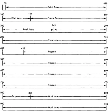
Instructions must be placed in core storage before they can initiate operations. The data that is to be processed must also be placed in core storage to be operated upon. Therefore, both data and instructions are in core stor-age during operation of the program. The allocation of areas in core storage for input data, output data, constants, and work areas is determined by the pro-grammer. Figure 5 shows how 1000 positions of storage, numbered 000-999, can be subdivided into areas. None of the areas is fixed in storage; i.e., the print area, for example, is not always assigned positions 001-120; it could just as easily have been assigned positions 801-920.
The Autocoder system of programming provides certain instructions to aid the programmer in defining areas. If these instructions are used, storage assignment is automatically performed by the Autocoder processor while the object program is being assembled. Auto-matic assignment of storage is described in greater detail in Sections 2 and 3. .
001
I
I~
Print Area100 120
\.. Print Area
~I~
Punch Area200 249
I-
Read Area~I~
300
I~
Constants400 415
I
I-
Program500
14
Program600
\-
Program700
I-
Program800 820
I_
Program-I-
Work Area900
I-
Work AreaFigure 5. Allocation of Areas in Core Storage
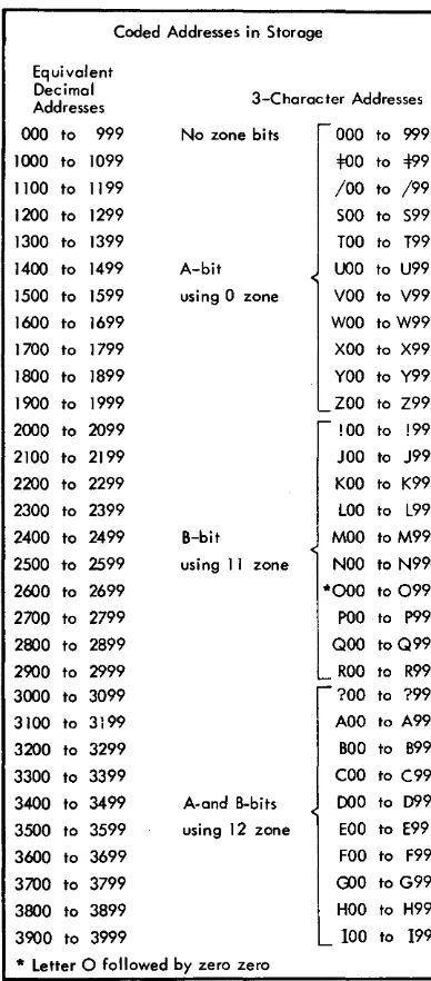
Each pOSitIOn of core storage is addressable by a unique 3-digit mixed alphameric address code. For the most part the programmer need not concern himself with these codes when programming in the Autocoder language. The coded addresses and their decimal equivalents for the first 4000 positions of core storage appear in Figure 6. Decimal numbers
o
through 15999are used when coding a program in Autocoder lan-guage. When the object program is assembled, these numbers are converted into 3-digit machine language codes.
The first one thousand 3-character addresses are coded in machine language as numbers between 000 and 999. Addresses of 1000 and over are handled in a special manner to fit into the 3-character format. The numerical bits of the three characters represent the units, tens, and hundreds position of the address. The
099
"I
199
~
I
299
~I
399
..
,
499
~I
599
~I
699
~
799
..
,
899
~I
999
-,
o
[image:12.617.41.395.344.707.2]c
Coded Addresses in Storage
Equivalent Decimal Addresses
000 to 999
1000 to 1099 1100 to 1199 1200 to 1299 1300 to 1399 1400 to 1499
1500 to 1599 1600 to 1699 1700 to 1799 1800 to 1899 1900 to 1999 2000 to 2099 2100 to 2199 2200 to 2299 2300 to 2399 2400 to 2499 2500 to 2599 2600 to 2699 2700 to 2799 2800 to 2899 2900 to 2999 3000 to 3099 3100 to 3199 3200 to 3299 3300 to 3399
3400 to 3499
3500 to 3599 3600 to 3699 3700 to 3799 3800 to 3899 3900 to 3999
3-Character Addresses
No zone bits
A-bit using 0 zone
000 to 999
too
to 499/00 to /99
SOO to S99 TOO to T99
UOO to U99
VOO to V99
WOO to W99 XOO to X99
YOO to Y99 ZOO to Z99 !OO to !99 JOO to J99 KOO to K99 LOO to L99
B-bit MOO to M99
using II zone NOO to N99
A-and B-bits using 12 zone
*000 to 099
POO to P99
QOO to Q99
ROO to R99
?OO to ?99 AOO to A99 BOO to B99 COO to C99
000 to 099
EOO to E99 FOO to F99
rno
to G99HOO to H99 100 to 199
* Letter 0 followed by zero zero
Figure 6. Core Storage Address Codes
zone bits B and A of the leftmost character are given values of 2 and 1, respectively, and are used to represent the thousands position of the address for addresses up to 3,999. The address
0123
whereas the address
2123
is represented as
Parity (C) bits are not shown.
Addresses over 3,999 are handled by using the zone bits of the rightmost character similarly. The B and A bits of this character are given values of 8 and 4, re-spectively, and ar"e combined with the bits from the leftmost character to represent the thousands and ten thousands positions of the address.
Bit Values Leftmost Zone
B=2
A= 1 Therefore, the address5486 is represen ted in core storage as
Rightmost Zone
B=8
A=4The coded address range for addresses 4,000 through 16,000 is shown at the top of the following page.
[image:13.615.74.268.71.512.2]Equivalent Zone Bits over
Decimal Hundreds
Char-Address acter Position 4000 to 4999 No zone bits 5000 to 5999 A bit (zero zone) 6000 to 6999 B bit (11 zone) 7000 to 7999 A, B bits (12 zone) 8000 to 8999 No zone bits 9000 to 9999 A bit (zero zone) 10000 to 10999 B bit (11 zone) 11000 to 11999 A, B bits (12 zone) 12000 to 12999 No zone bits 13000 to 13999 A bit (zero zone) 14000 to 14999 B bit (11 zone) 15000 to 15999 A, B bits (12 zone)
Section
J.
Questions
1. High-volume printed output is normally obtained from
a. 1443 Printer
b. 1447 Console I/O Printer
2. If input data is used as output-as, for example, when listing from cards-does this input data go through the processing unit?
3. Can a record which is stored in the processing unit be stored on the disk, be printed out, and be punched into a card?
4. How many alphabetic characters can be stored in 4,000 positions of storage?
5. Which statement is true?
a. A card must pass the punching station before it can be read.
Zone Bi ts over
U ni ts Character 3-Character
Position Address Range
A bit (zero zone) O0=F to 99Z A bit (zero zone) =F0=F to Z9Z A bit (zero zone) !0=F to R9Z A bit (zero zone) ?0=F to 19Z B bit (11 zone) OO! to 99R B bit (11 zone) =F 0 ! to Z9R B bit (11 zone) !O! to R9R B bit (11 zone) ?O! to 19R A, B bits (12 zone) OO? to 991 A, B bits (12 zone) =F 0 ? to Z91 A, B bits (12 zone) !O? to R91 A, B bits (12 zone) ?O? to 191
b. A card must pass the reading station before it can be punched.
6. What are three of the fundamental functions of the processing uni t?
7. How many characters with word marks can be stored in one disk sector? How many characters without word marks?
8. What is the range of sector addresses on cylinder 00 of the second disk drive?
9. What are the five digits that precede each data sector called?
10. Are all positions of core storage addressable? 11. Besides identifying the first position of an
instruc-tion, what is another function of the word mark?
0
()
c
Introduction to Programming
Section 2
In Section 1 we described the components of the IBM 1440 Data Processing System and the characteristics of core storage. In this section, we will concern our-selves with the fundamentals of programming and the methods of programming the 1440 itself. This will in-volve an exploration of the purpose of programming and its functions in data processing. Finally, we will point out the programming details that the program-mer must pay attention to, the form that he will use in writing a program, and the method he will employ to describe data.
Purpose of Programming
Data processing by any method requires that an orderly procedure of steps or operations be followed. This pro~
cedure must be translated step-by-step into a series of
instructions, arranged in logical sequence, which the computer can perform. The series of instructions is known as a program.
Function of the Programmer
There are two major tasks a programmer must perform to develop a program:
1. To establish the requirements of the problem and the requirements of the solution.
2. To write the program for the computer to follow. The first task, a systems study, requires that the pro-grammer define the problem in the broad sense: choose the machine or computer configuration; and establish the format or layout of report forms, records, and cards. The second task requires that, preliminary to the actual writing of the program, the programmer define the problem in a step-by-step analysis and work out the logic of the program in the documented form of block diagrams or the recently developed decision tables or by using both. Either form of documentation is ac-ceptable: both are immeasurable aids.
In the programming examples presented in this book, we have provided both forms of documentation, leaving
it up to the student to choose the one he is more fa-miliar with or the one he prefers.
Language of Programming
Problems for the computer can be coded in actual ma-chine language (absolute) if the programmer knows the language of the particular computer; however, even beyond the problems of the machine language itself, the method is often difficult in other respects: in assign-ing storage locations, in correctassign-ing or modifyassign-ing pro-grams, and in cross referencing within a program. For these reasons, other languages have been developed. We shall use the language called Autocoder for it most nearly eliminates these difficulties. The use of Auto-coder language almost completely precludes the pro-grammer's need to know how the computer operates on each and every instruction or how the data is repre-sented in storage. Therefore, we will delay describing machine functions until we have presented the prin-ciples of programming.
In summary, the advantages of using Autocoder rather than machine language for our program are:
1. We can use symbolic addresses in the coded pro-gram in place of actual addresses.
2. We can replace actual codes in the coded program with mnemonic operation codes that are de-scriptive and more meaningful.
3. The processor, while it is translating our symbolic source program into an actual (machine lan-guage) object program, edits our source program and uncovers coding errors.
Here is a specific set of actual machine language ins tructions.
M % G 1 A 1 2 R
AA 2 5 A 3 5
AA 3 0 A 3 5
MA 3 5 D 3 5
M% G D 2 P
If we write them in Autocoder language, they will look like this:
Operation Operands
R 1, RDAREA
A AFIELD, SUM
A BFIELD, SUM
MLC SUM, PCFIELD
P PCAREA
Each line represents one instruction. These instructions direct the computer to do the following:
No. I tells it to Read a card into the storage read area which is symbolized by "RDAREA."
No.2 No.3 No.4
No.5
Add amount of "AFIELD" to amount "SUM."
Add amount "BFIELD" to amount "SUM"
Move the amount "SUM" to its punching location symbolized by "PCFIELD."
Punch a card from the data at the punch area symbolically represented by "PCAREA."
From this example, we can see that operands of an instruction are written immediately adjacent to one another and are separated only by a comma, a require-ment of the Autocoder language.
These Autocoder instructions must be transcribed into punched cards, for it is the cards that become the actual input (source program) that the processor will assemble as an object program to be run by the com-puter. The object program produced by the Autocoder processor contains its own loading instructions; that is, it has instructions for automatically loading itself into its assigned areas of storage when it is entered into the 1440 system.
We may want to edit our source program to uncover coding errors and to be able to correct these errors before proceeding to produce the object program in card form. The edit pass produces an edited program listing. With this listing, we can correct our mistakes, again process the corrected input cards (the source program), and produce the final object program in both card and list form.
1
Edit
v
Pass Source Pragram
Edited
1440 Pragram
System listing
(Using Autocoder Processor}
-1
II
1
U~ I~ to correct
Source Pragram ~---Source Program Assembly
Pass
r1
~ V
Object Pragram 1440
System
(Using Autocoder Pracessor) Pragram Listing
~
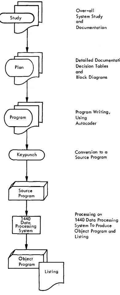
The program listing gives the original Autocoder instructions, the assembled instructions, the error mes-sages, and the assignment of storage for instruction and data. This listing is used later to debug the pro-gram. Debugging is testing the program for errors until all errors (bugs) are eliminated. Figure 7 depicts the steps thus far described.
In our description of Autocoder language, we showed some operations and operands and referred to these as program instructions. No mention was made of any particular format in which these instructions should be written because the purpose of the example was to illustrate the difference between machine language and Autocoder language. If we wish to write these Auto-coder instructions properly for machine usel we will
have to write them in the format prescribed by the Autocoder coding sheet.
o
c
Over-all System Study andDocumentat ion
Detailed Documentation, Decision Tables and
Block Diagrams
Program Writing, Using
Autocoder
Conversion to a Source Program
Process i ng on 1440 Data Processing System To Produce Object Program and
Listing
Figure 7. Steps in Preparing an Object Program
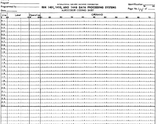
Use of Autocoder Coding Sheets
The programmer enters all program entries on the Autocoder coding sheet (Figure 8) . The column num-bers on the coding sheet indicate the punching format for all input cards in the source deck. Each line of the coding sheet is punched into a separate card. The func· tion of each field of the coding sheet is explained, as follows:
Page Number (Columns 1-2)
This entry provides sequencing for coding sheets.
Line Number (Columns 3-5)
This entry provides sequencing for lines within a cod· ing sheet. The first 25 lines are prenumbered 01-25. The source program cards must be in ascending line num-ber order when they become input to the system.
Label (Columns 6-15)
A symbolic label can have as many as six alphameric characters. The first letter of the label is always written in column 6; the character contained in this position must be alphabetic.
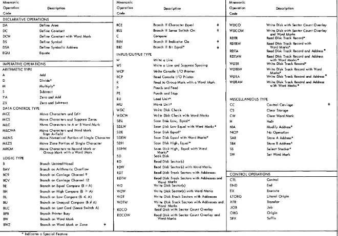
Operation (Columns 16-20)
Mnemonic operation codes are written in this field, starting in column 16. Table 2 shows the Autocoder mnemonics for declarative operations, imperative op-erations, and control operations. Declarative operations
are described as being those that are used to reserve areas and to store constants. Imperative operations are
those that are converted, one for one, into instructions or program steps in the object program. Control
opera-tions are those that enable the programmer to exercise some control over the assembly process.
Operand (Columns 21-72)
The operand field in an imperative instruction can contain:
I. The actual or symbolic address of the data to be acted upon, as directed by the command in the operation field. (NOTE: a label that appears as an operand is considered a symbol.)
2. The actual data to be operated upon; data in this form is referred to as a literal.
3. The address constant, i.e., the symbol which repre-sents the actual 3-character address that is assigned to the corresponding label. (A plus or minus sign must always precede an address constant so that the processor can distinguish it from a symbolic address.)
Operands in Autocoder language are always sepa-rated by commas. The statement that follows demon-strates the use of commas. This instruction causes data specified by the A operand (actual address 3101) to be added to the data specified by the B operand (actual address 140) .
label I ~perati~ I OPERAND
•
25 50 55 40 45 50I l~ 3 10 1 140
I
, I
[image:17.620.80.275.71.549.2]IBJ.1
Program _ _ _ _ _ _ _ _ _ _
INTERNATIONAL BUSINESS MACHINES CORPORATION Identification I I
Programmed b y - - - - -_ _
Date _ _ _ _
IBM 1401, 1410, AND 1440 DATA PROCESSING SYSTEMS
AUTOCODER CODING SHEET
76 80
Page No. LJ...J of _ _
I 2
Line label pperation OPERAND
3 56 1516 2021 25 30 35 4Cl 45 50 55 60 65 7Cl
0 I :
o 2 :
o 3
:
o 4 :
05
:
06
:
o 7
:
.
I
08 I
09 :
I 0 I I
I
I I I
I
I 2 I
I 3
:
I
I 4 i I
I
I 5 I I
I 6 I I
I
I 7 I I
I 8 I
I 9 : I
2 0 :
.
I
2 I I
2 2 I I
2 3 I
I
2 4 I
2 5 :
I
-~ --L....L I I I I ~~----'---'---L--L~-LI I I I I I I I I I I I I I I I I I
I
1
I
I I I I I I I I I
I
1
:
Figure 8>. Autocoder Coding Sheet
Note that the first and second operands of an impera-tive statement are referred to as the A and B operands. A third operand is called the d-modifier. The next state-ment is an example of a statestate-ment that contains all three operands.
16
Label sfsperati~
1 5 1 6 2 0 2 1
I I I
25
I I I I I I I I ~--l..~
I
This instruction, when assembled, tests the storage location equivalent to SWITCH for a digit 2 and branches to the location equivalent to ENTRYA for the next in-struction, provided SWITCH contains a 2. The digit 2 is the d-modifier. Only certain Autocoder operations re-quire a d-modifier. They are indicated by
t
in Table 2. The programmer can include a remark or comment anywhere in the operand field, if he leaves at least two blank (nonsignificant) spaces between the remark and the operand. If he added a comment to the previous statement, it would appear as follows:OPERAND
5n 5" 40 45 50 55 50 65 70
I IBeE ENT.RYA SWITCH 2 TEST SW Fo.R A DI.GIT 2 AND BRANCH. I I I
o
[image:18.617.35.544.85.486.2]...
;::::
"""'
c i;:l..
.:
~
c·
;::::
0-~
c
\Jq
~
;;:; ;;:;
~.
...
\C
a
o
~
Table 2. Autocoder Mnemonic Operation Codes
Mnemonic Mnemonic Mnemonic !
Operation Description Operation Description Operation Oescr i pti on
Code Code Code
DECLARATIVE OPERATIONS
DA Define Area BCE Branch If Character Equal 4= WDCO Write Disk with Sector Count Overlay DC Define Constant BSS Branch If Sense Switch On :I: WDCOW Write Disk with Sector Count Overlay
DCW Define Constant with Word Mark C Compare and Word Marks
RDTR Read Disk Track Record* OS Defi ne Symbol BIN Branch If Indicator On
...
RDTRW Read Disk Track Record with DSA Define Symbolic Address BBE Branch If Bit Equal* =4= Word Marks*
EQU Equate IN PUT/OUTPUT TYPE ROTA Read Disk Track Record and Address *
RDTAW Read Disk Track Record and Address
W Write a Line with Word Marks *
IMPERA TIVE OPERA nONS WS Write a Line and Suppress Spacing WDTR Write Disk Track Record* ARITHMETIC TYPE
WCP Write Console I/O Printer WDTRW Write Disk Track Record with Word Marks* A Add RCP Read Console I/O Printer WDTA Write Disk Track Record and Address *
D Divide*
R Read to Group Mark with a Word Mark WDTAW Write Disk Track Record and Address
M Multiply* P Punch and Feed with Word Marks·
S Subtract
PS Punch and Stop
ZA Zero and Add LU Load Unite MISCELLANEOUS TYPE
ZS Zero and Subtract MU Move Unite
CC Control Carriage 4=
DAT A CONTROL TYPE WDC Write Disk Check
CS Clear Storage MCE Move Characters and Edit WDCW Write Disk Check with Word Marks
CW Clear Word Mark MCS Move Charac ters and Suppress Zeros SDL Scan Disk Low, Equal*
H Halt
MLC Move Characters to A or B Word Mark
SDLW Scan Disk Low Equal with Word Marks * MA Modify Address* MLCWA Move Characters and Word Mark SDE Scan Disk Equal*
NOP No Operation frQm A-fie Id
MLNS Move Numerical Portion of Single Character SDEW Scan Disk Equal with Word Marks* SAR Store A Address* MLZS Move Zone Portion of Single Character SOH Scan Disk High, Equal* SBR Store B Address* MRCM Move Characters to Record Mark or SDHW Scan Disk High, Equal with Word SS Select Stacker*
Group Mark with a Word Mark Marks*
SW Set Word Mark
LOGIC TYPE SO Seek Disk
B Branch Unconditional RD Read Disk Sector{s)
BAV Branch on Arithmetic Overflow ROW Read Disk Sector{s) with Word Marks
BC9 Branch on Carriage Chonnel 9 ROT Read Disk Track Sectors with Addresses CONTROL OPERATIONS BCV Branch on Carriage Channel 12 RDTW Read Disk Track Sectors with Addresses and
cn
ControlWord Marks
BE Branch on Equal Compare (B = A) WD Write Disk Sector{s) END End BH Branch on High Compare (B > A) WOW Write Disk Sector{s) with Word Marks EX Execute BL Branch on Low Compare (B 1( A) WDT Write Disk Track Sectors with Addresses LTORG Literal Origin BU Branch on Unequal Compare (B F A) WDTW Write Disk Track Sectors with Addresses and XFR Transfer BLC Branch on Last Card (Sense Switch A) Word Marks JOB Job
RDCO Read Disk with Sector Count Overlay
BPB Branch Printer Busy RDCOW Read Disk with Sector Count Overlay and ORG Origin
BW Branch on Word Mark Word Marks SFX Suffix
BWZ Branch on Word Mark or Zone 4=
* Indicat~s a Special Feature
... Indicates that the programmer must supply d-modifier in Autocoder Statement
--A comment in no way affects the assembled machine language instruction, however it does appear on the program listing opposite the assembled instruction.
In preparing a program, it is necessary to determine the constants and storage areas that are needed, and to define them. Usually this step is completed before the program is written; however, it may be accomplished
as the program is being written.
Symbolic Assignment of Core Storage
In Autocoder language, assignment of symbolic names (labels) to data fields, constants, or instructions re-lieves the programmer of the problem of keeping track of actual storage locations. The programmer should assign names that are meaningful. For example, he might label a 6-position field reserved for withholding tax as WHTAX. A word of caution-once he has assigned this label, he must be careful not to assign it to two different fields.
The Autocoder processor program assigns the actual storage locations as it produces the object program. The Processor has a location assignment counter for this purpose. The counter is set at 210 at the start. Each time the processor assigns an area, the counter is incremented by the number of positions in that area. The last number in the assignment counter is the ad-dress of the area.
A 4-position constant (for example, ABeD) is assigned the address 213, provided the assignment counter was set at 210 when the statement defining the constant was encountered. Subsequent statements will be as-signed storage in the order in which they are encoun-tered. The Autocoder language contains control in-struction that allow the programmer to preset the counter to a particular address or to change the setting of the counter during assembly. Thus, the programmer can start the assignment of storage at any address he specifies.
There are no permanently assigned areas within cOre storage except for storage positions 0087-0099 which are used by the Indexing feature (a special feature) . Areas for input and output are assigned by the processor to areas which it selects (unless specified otherwise) and with one restriction. The leftmost position of an area reserved for printing on the 1443 Printer must be an address that ends with 01 (XX01).
The Autocoder instructions used to create constants and to reserve areas in core storage are known as Declarative operations. Here we describe some of the ways to write these instructions and show how the processor operates upon them.
Storage Assignment with Declarative Operations
DCW Define Constant with Word Mark
6
This operation is used to create alphameric or numerical constants, address constants, or blank areas, in core storage as part of the object program. A word mark is automatically added to the leftmost position of the created field.
A numerical constant can be given a plus or. minus value by preceding it with a
+
or - sign in the statement in which it appears. Numeri-cal constants take the following formLabel 15~perati~ I OPERAND
25 30 35 40 45 50
CONST 11 new +1234
CONST 2' DCW - 5 6 3 2
CONS:r 3' DCW 1234567
6
I
, ! ! ,
where the constant itself may be any number of characters. The address that is associated with the label of the constant will be that of the rightmost position of the constant itself. An alphameric constant or a blank constant can also be defined; these constants must be pre-ceded and followed by an "at" (@) sign.
Label 15~perati ~ 2 I OPERAND
25 30 35_ 40 45
CONST 4 DCW @E,RROR ,MESS A.GE 1~
CONST 5' DCW !i!JANUA,RY 28 1962,(ci)
~N,ST 6: Inew @ @
DC
•
c--'---'--CONST6, which is a 9-position blank field, can also be defined by the following statement;
OPERAND
4
where the # symbol precedes the number that tells how many blank storage positions are to be defined.
Define Constant
This operation is the same as the DCW opera-tion except that a word mark is not added by the processor to the leftmost position of a field being defined. The statements are written in
the same manner as DCW statements.
o
c-c
DS
DA
Define Symbol
This operation is used to reserve an area of core storage and to associate a label with the ad-dress of that area. Unlike the DCW or DC op-eration, the DS operation does not load any data as part of the object program.
OPERAND
4
In the example given, the number of positions to be reserved is ten, as specified by the value of the number in the operand field.
Define Area
The DA operation is used to define an area for input or output and to place a group mark with a word mark in a position immediately to the right of the area. This operation is un-like the declarative operations described so far, where the address associated with the label is the rightmost position of the area. The address of a label associated with a DA statement is the
leftmost position of the area. Entries following the DA entry are used to define fields and sub-fields that fall within the limits of the area. For example, the statements
Label OPERAND
I1Line 56 15~perati~ 21
..
3<> 3' 40 4' o Io 2 03 04 05 06 07 08
0 ' 10 I I
I 2 I 3
I 4 I 5 I 6
I TE.M IDA. 1X,53 G LAYOUT OF ITE M, CA.Rn
ODE I
1 1
!DATE I
2 5 FIELD
MO I
3 .RTT,RF.TFLn
iDAY I
5 SUBFIELD
SLMNO I
6 8
C.LASS I 9 ,13
U,p I
.4 1.<1
Q,TY,s ~ 20" 2 2
b,TYBO I
12.3 .2.5
l.\,MT I
12.6 3 1
isUBS I ~ .2 .• 3.7
TMNO ~ 8 45
Q.TY kt 6., 48
ic.us~o 149 53
I I I I I I
reserve a 53-position storage area followed by a group mark with a word mark. The first posi-tion of the area becomes the first field, the sec-ond through fifth positions become the secsec-ond field, etc.
6
A field within a field is called a subfield. MO and DAY are subfields of the DATE field. In the
example, the rightmost position of the sub fields is written in column 21. Word marks are not generated by the processor for subfields.
A word mark is automatically generated in the leftmost position of each field, provided there are two numbers in the operand field and these are separated by a comma. The data gen-erated by the statement appears in the object program as:
QQbbbQbbQbbbbQbbbbbQbbQbb9bbbbb9bbbbbQbbbbbbbQbbQbbbb~
where
Q represents a blank position with a
word mark, b represents a blank position, andG
M represents a position which contains both a group mark and word mark. The address of the rightmost position of each field is associated with its corresponding label.
The following statements show how three similar areas, each followed by a record mark)
can be defined.
Label pperatiOl'1
..
OPERAND1516 '0 I 3n 35 4<> 45 RECBL.K IDA 3X5.,j, G
INAME I 1 2
IDATE I 3 5
I
These statements generate
as a part of the object program. The number in column 21 in the operand field specifies the number of times the fields should be repeated.
EQU Equate
6
This operation is used to assign a label to an actual or a symbolic address. It allows the pro-grammer to assign different labels to the same storage location and to refer to the storage loca-tion by either name. No storage is reserved and no data is loaded as part of the object program when this operation is used.
Label 15~perati~
21 2. 30 35 40 OPERAND 45
I ND l.v, IE£HT. MAN,N,n
I
Suppose, for example, that the symbol MANNO is assigned the address 1234 by the processor. When the EQU operation is encountered, the label INDIV will be assigned the same address
(1234) .
Section
2.
Questions
I. What are the two major tasks of a programmer? 2. What is the name of the programming language we use in writing instructions for the 1440 system? 3. Area definition statements are used for which of
these?
4.
5.
a. to instruct the machine to perform arithmetic. b. to assign storage areas for data.
c. to control the processor function. d. to write instructions for the computer.
If the statement shown above is entered in a pro-gram, will subsequent statements using the symbol READIN be addressing:
a. the leftmost position of the area reserved? b. the rightmost position of the area reserved?
The following statement equates the label NETPAY to an actual address.
OPERAND
4
In this example the address of the constant as-sociated with the label DATE will be:
a. the address of the leftmost position of the constant.
b. the address of the rightmost position of the constant.
7. What is the difference in the result of these two statements?
Label I fsperati~ I
2S 30 3S
6 40
D,ATE DCW la DEQ ~
DATE I DC ~ DEC @ I I
I
8. Correct the following statements.
Label I fsperati ~ I
30 35
6 25 40
~ON ST 1 DCW @E,RROR LIS T IN.G .@.
14TH I D,C,W 12.3.4.5 ,6
.DATE I DC taJ DEC 9 @
I
A 12962 720
IR,E.AD r N: DA. 1 80
DATE I D.CW J>,V
1
Programming a Basic Job
Section 3
Since we are now familiar with the programming tools that are used in planning and coding a job, we will proceed to program a basic job. In this job, two factors are to be read from a card, added together, and the total punched into the same card.
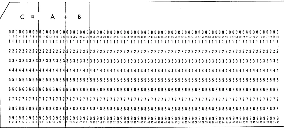
Figure 9 shows the format of the input cards. Field B is to be added to field A and punched into field C. Whenever possible, the field or fields that are to be punched should be located near the column-1 end of the card. This arrangement minimizes the time re-quired to punch each card and thereby maximizes card throughput. The term card throughput refers to the
number of cards per minute that can be processed by the system for any given job.
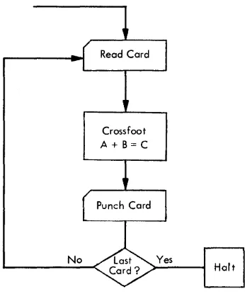
Block diagram, Figure lOA, and decision table, Figure lOB, initiate the program with the reading of a card.
I
c =
A
+
B
The second step is finding the total of A plus Band punching the result. The third step is a test for last card. The fourth step is a branch back to the first action (read a card). These four steps are repeated for each card until all cards are processed.
Twelve Autocoder statements (see Figure 11) consti-tute the coded program. The first three statements de-fine the core storage area into which the card is read; the next two statements define the area from which the card is punched; and the remaining seven statements are the imperative statements that make up the pro-gram instructions. This ordering of the statements is
only one possibility; the imperative statements could have been written or could have appeared first and been followed by the five declarative statements.
00000000000000000000000000000000000000000000000000000000000000000000000000000000
1 2 3 4 5 6 7 8 9 10 11 12 13 14 15 16 17 18 19 2021 22 23 24 15 ,6 2) 18 29 30 31 31 33 34 3" 31i 37 3h 39 40 41 42 43 44 45 4" 4: ~r. 4, 50 51 57 ,,54 ;, ',6 5) 58 59 60 61 [;16: &4
,i
'ti './ G8 69 '1 )l )2 13 14 )5 )fi 1/ ;~ 79 af;111111111111111111111 i 1111111111111111111111111111111111111111111111111111111111
22222222222222222222222222222222222222222222222222222222222222222222222222222222
33333333333333333333333333333333333333333333333333333333333333333333333333333333
44444444444444444444444444444444444444444444444444444444444444444444444444444444
55555555555555555555555555555555555555555555555555555555555555555555555555555555
66666666666666666666666666666666666666666666666666666666666666666666666666666666
77777777777777777771777777777777777777777777777777777777777777777777777777777777
8 8 8 3 8 8 8 8 8 8 8 8 8 8 8 8 818 8 8 8 8 8 8 8 8 8 8 8 8 8 8 8 8 8 8 8 8 8 8 8 8 8 8 8 8 S 8 8 8 8 8 8 8 8 8 8 8 88 8 8 8 8 8 8 8 8 8 8 8 8 8 8 8 8 8 8 8 8
~~~~~~~~~~~~~~~~~~~!~!~~!!~!~!~!~!!!~!~!~!!!!!!!~~~~~!~!~!~!~~!!!~~~!!~~!~~~~!~!
Figure 9. Card Format for A
+
B = C [image:23.612.77.564.487.712.2]Crossfoot A + B = C
Figure lOA. Block Diagram for A
+
B = CA detailed analysis of the coding sheet is given in Figure 11. Line 01 of the coding sheet reserves 24
posi-tions in storage and one additional position for a group mark with a word mark.
Reserving an Area for Card Reading. The
number of positions the programmer re-serves must equal the highest-numbered card column to be read. In this example, the highest-numbered card column is 24 (see Figure 9) . The label RDAREA will be assigned the address equivalent to the leftmost posi-tion of the read area when the program is assembled.
Lines 02 and 03 assign the labels AFIELD and BFIELD to the addresses of the A and B factors, respectively.
Line label pperation
3 56 1516 2021 25 30 35
o I R,DARE.A: ~,A 1X24 G
o 2 A Ft~LJ>i 10" 1 7
o 3 BFIEL.D: 18. 24 04 PCHAR.Al ~,A 1;X 9.f G
o 5 C FI ELD: 1 9
o 6 START : R 1, RDARE A
o 7 I I Z.A, A FI ,E,4.D C FI f,: L.D,
o 8 I I IA BFIE,LD IC,FIE LDL
o 9
:
P,S 1,. P C,IlA RA I 0:
iB,L.C iH.A.L'l',I
I I I B START
I 2 H.A.LT I I H
I 3
:
Figure 11. Coding Sheet for A
+
B = C40
**
START I1 'HAS LAST CARD BEEN PROCESSED ? NIY I
~--I
X
2 IREAD gARD I
X
~_ETC =A
I +B X
~ ..
+---.1 :pl.1N~:m CARD X
I
~
f-_!1.-:~OP
I
'
-Figure lOB. Decision Table for A
+
B = CIn effect, the two fields wi thin the read area are defined and word marks are placed in the leftmost positions of the fields to identify their limits. Because the processor initiates assignment of storage, the read area will start in storage position 210 and will extend into higher-numbered positions, as shown:
A Field B Field
bbbbbbbbb~bb~bbbB~bbbbb~~
t
-
-
-210
Line 04 reserves a 9-position punch area labeled
PCHARA and sets a group mark with a word mark in the position to the immediate right of the area.
Reserving an Area for Card Punching. An
area reserved for punching must contain the number of positions equal to the highest-numbered card column to be punched. The position to the right of this area must con-tain a group mark with a word mark.
OPERAND
45 50 55 60 65
QEiFINE READ AREA
DEiFI~ E ,PUNCH AREA
READ A CARD IN TO READ AREA GEQSSFOO T
PU~CFl F.RO,M, PUNC H ,ARcEA T.EST FO.R LAST CARD, END
I I I I I I I I I I I I I
o
o
Line 05 assigns the label CFIELD to the address equivalent to the rightmost position of the field to be punched. A word mark is set in the leftmost position of this field, thus identifying its limit.
After assembly, the combined read and punch areas reserved by the first five statements will appear as:
A Field B Field C Field
bbbbbbbbtibbb~bbb~bbb~bb6~bbbb~bbbB~
t
-
-
--
-210
Line 06 initiates a card reading operation that causes card columns 1-24 to be read into core storage, starting at position 210. The first group mark with a word mark encountered terminates the transfer of data to storage.
Card Reading Operation. In a card reading
operation, the A operand (1) is a constant that specifies card reading is to be performed by the 1442 Read-Punch, Unit Number l. If the constant (A operand) contained a 2, the card reading operation would be per-formed instead by Unit Number 2 (special feature). The symbol RDAREA specifies the address in core storage where the storing of data starts (position 210), i.e., where the data from card column one is stored. We will want to branch back (return) to this instruction from another point in the pro-gram, therefore we must give it a label. The label START causes the address of the instruc-tion to be saved for further use during the assembly of the object program.
Line 07 is a ZA statement which resets to zeros the field in the punch area containing the C factor and then adds the A factor into the cleared area.
Zero and Add Operation. In a ZA statement,
the A operand specifies the field to be added whereas the B operand specifies the field to be cleared (reset to zeros) . Data to be added is transmitted, starting with the rightmost position. A word mark terminates the opera-tion.
Word Marks in Arithmetic Operations. The A-field word mark stops data transfer from the A field. The B-field word mark stops the operation and data transfer.
Therefore, if both fields are of equal length, only the B-field word mark must be present. If the A field is shorter than the B field, a word mark must be present in both fields.
We will find that this use of word marks is the same for all other. arithmetic operations with the exception of multiply and divide (special features). In our ex-ample, word marks have been set in the leftmost posi-tion of the fields by the DA statements. These word marks are not erased or affected by an arithmetic op-eration.
Line 08 adds the B factor to the A factor to produce
the total C.
Add Operation. In an Add (A) opera tion,
the data addressed by the A operand is added to the data addressed by the B oper-and, digit by digit, starting in the rightmost position. The total that is developed re-places the data previously stored at the B address.
The use of word marks in an Add opera-tion is the same as in the ZA operaopera-tion just described.
Line 09 initiates a card punching operation. The A operand indicates that the punching is to be performed by the Read-Punch, Unit Number 1. The B operand PCHARA is the address of the leftmost position of the core storage area to be punched.
Card Punching Operation. The A operand
specifies which Card Punch unit is to be used: code 1 for Punch unit, Number 1 and code 2 for Punch unit, Number 2. Punching starts with the addressed position and con-tinues through higher-numbered positions until a group mark with a word mark termi-nates the operation. Either the PS operation code (Punch and Stop) or the P operation code (Punch and Feed) can be used to start the punching operation.
If the PS operation code is used, the card remains at the punching station after punch-ing is completed until the next card is read or until a P