Systems Reference Library
IBM 1620 Central Processing
Unit,
Model 2
File No. 1620/1710-01
Form No. A26-5781-2
This manual contains basic programming and operating informa-tion for the 1620 Model 2 Central Processing Unit as it is used in the 1620 Data Processing System and in the 1710 Control System. Comprehensive information is included on core storage, computer
instructions, data How, and console operation.
This is a reprint of an earlier publication; it incorporates the follow-ing Technical Newsletters:
Form No. Pages Dated
N26-0117 47, 48, 55, 56, 57, 58 4/1/65
N26-0129 37, 38, 109, 110 7/19/65
N26-0140 13, 14, 21, 22, 41, 42, 43, 44, 11/8/65 49, 50, 69, 70, 75, 76, 95, 96
Copies of this and other IBM publications can be obtained through IBM Branch Offices. Comments concerning the contents of this publication may be addressed to:
Page
1620 Data Processing System, Mod~1 2 ... 1
1620 Central Processing Unit, Model 2 . ... " 5 Data Presentation ... 5
Magnetic Core Storage ... 6
1620 Additional Units. . . .. 9
Paper Tape Unit ... " 9 Tape Punch ... 9
Card Read-Punch ... " 11 Printer ... 12
Disk Storage ... 14
Plotter ... 17
1620 Instructions . ... " 19 Stored Program Concept ... 19
Instruction Characteristics ... 19
Indirect Addressing ... 20
Instruction Types ... 23
Arithmetic Instructions ... 23
Logic Instructions ... 33
Internal Data Transmission Instructions ... 38
Input/Output Instructions ... 42
1311 Disk Storage Drive Instructions ... 46
Program Control Instructions ... 52
Floating Point Instructions ... 55
Index Registers Instructions ... 60
Binary Capabilities Instructions ... 64
1620 Console Machine Status and Program Switches ... 71
Control Switches, Keys, and Signal Lights ... 74
Register Display Indicators ... 76
Machine Status Lights ... .. 77
Console Typewriter ... " 85
Contents
Page 1620 Console Operating Procedures. . . .. 91Program Entry from Typewriter . . . .. 91
Program Entry from Paper Tape Reader ... 91
Program Alteration and Data Entry . . . .. 92
Typewriter Output ... 92
Check Program Step Sequence and Operation . . . .. 92
Reset Core Storage to Zeros . . . .. 93
Display P and Q Addresses . . . .. 93
Timing ... 94
1622 Card Read-Punch ... 94
1443 Printer for the 1620 ... 95
1311 Disk Storage Drive ... . . . .. .. 96
Console Typewriter ... 98
Paper Tape ... 98
Plotter ... 98
Estimating Process Time ... 99
Throughput Timing ... 99
Appendix A . . . .. 105
Instruction Summary ... 105
Appendix B. . . . .. 108
Bit Configuration of Decimal Digits Multiply Table Table Areas in Core Storage 1620 Storage Register Functions Appendix C. . . .. 109
Character Coding Chart Appendix D ... III Core Storage Data Resulting from Reading Alphameric Card Data with RN Instruction Appendix E Program Load Routines... 112
Paper Tape Load Routine . . . .. 112
Card Load Routine ... 113
The IBM 1620 Model 2 Data Processing System is an electronic computer system designed for scientific and technological applications. The use of solid-state cir-cuit components and the availability of from 20,000 to 60,000 positions of core storage provide the 1620 Sys-tem with the capacity, reliability, and speed to solve problems that in the past have required the use of larger and more expensive data processing systems.
Seven units are available with the IBM 1620 Model 2
Data Processing System.
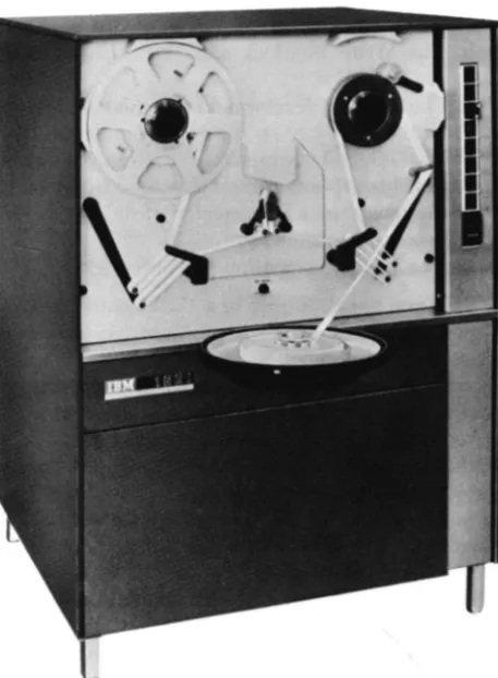
Central Processing Unit
The IBM 1620 Model 2 Central Processing Unit contains
the computer circuitry, an operator's panel, and an input/output (I/O) typewriter. The operator's panel of the 1620 contains control keys, switches, an indi-cator panel, and a typewriter. The control keys and switches are used for manual or automatic operation of the system. The indicators provide visual indication of the status of various registers, indicators, and I/O units. The typewriter allows operator entry of data and instructions into core storage; it also provides a permanent log of the operator's intervention during the execution of a program. The typewriter prints at a maximum speed of 15.5 characters a second. The operator's typing speed determines the rate of entry of information through the typewriter.
MODEL 1 SYSTEM
The 1620 Model 2 Data Processing System is com-pletely compatible with the Modell system. In almost all cases a program that runs on the Modell will also run on the Model 2. Programming changes will be re-quired only where unusual program conditions occur, such as where the program has used the timing of instructions (for example in a program loop) to syn-chronize an I/O function, or where add tables, which are not 'present in storage in the 1620-2, have heen modified to change the function of the add instruction. This publication describes the operation of the Model 2 only. The features of the Modell Central Processing Unit (cpu) are described in the publication
IBM 1620 Central Processing Unit, Model 1 (Form A26-5706).
Paper Tape Reader and Punch
Paper tape input/output operations are permitted by
the IBM 1621 Paper Tape Unit, which also includes the
1620 Data Processing System, Model 2
paper tape controls and the Tape Punch. The 1621 reads 8-track paper tape at the rate of 150 characters a second (cps). The Tape Punch operates at a rate of 15 cps.
Card Read-Punch
The IBM 1622 Card Read-Punch is available in two
models for card input/output operations. The 1622 Modell reads 80-column cards at the rate of 250 cards per minute (cpm) and punches cards at the rate of 125 cpm. The 1622 Model 2 reads at the rate of 500 cpm and punches at the rate of 250 cpm. However, throughput for the system is not dependent entirely upon reading and punching speeds because both models of the 1622 contain, as a basic feature, read and punch buffers that permit overlapping of reading and punching operations with other input/output op-erations and with processing opop-erations.
Printer
The IBM 1443 Printer, Models 1 and 2, are available
for large-volume output printing operations. The print-ing speeds for each model depends upon the particular character set used with the system. The Modell prints at the rates of 150, 190, or 430 lines a minute. The Model 2 prints at the rates of 240, 300, or 600 lines per minute. Both models of the 1443 contain, as a basic feature, a print buffer that permits overlapping of printing operations with other input/output operations and with processing operations. Both models can print either 120 or 144 characters on one line.
Disk Storage
The 1311 Disk Storage Drive provides virtually un-limited random and sequential access storage. A disk pack containing 2,000,000 digits of information can be removed from the 1311 and another pack put in its place in one to two minutes.
The ease of mobility of a disk pack (the weight of the pack is less than ten pounds) and the simplicity of its removal from the drive means that 2,000,000 digits of data can be placed in the system within seconds. Up to four disk drives, each equipped with one disk pack, can be placed «on-line" to make possible the availability of a total of 8,000,000 numerical characters
at one time (equivalent to 100,000 80-column IBM
Disk storage timing depends upon the access time
required to position the read/write heads over the
ap-propriate disk storage record, and upon the rotational
time required for the record to be positioned under a read/write head.
The average access time which depends upon where the data is located in disk storage, may range from 132 ms to 250 ms. However, the 1620 Data Processing Svs-tern has, as a basic feature, the ability to overlap seek, input/ output and processing operations. The average rotational time is 22 ms.
Core Storage
Core storage for the 1620 Model 2 is contained in the 1625 Core Storage Unit. Three models of the 1625 are available. The 1625-1, which is a basic unit of the sys-tem, contains 20,000 positions of core storage; the 1625-2 contains 40,000 positions; the 1625-3 contains 60,000 positions of core storage. Except where other-wise speciBcally noted, this manual is concerned with the basic 20,000 position system.
Plotter
The IBM 1627 Plotter enables the 1620 Data Processing
System to illustrate digital data in any desired physical form. Two models of the 1627 are available. The Model 1 has a plotting area of 11 inches by 120 feet and operates at a rate of 18,000 steps/minute. The
Model 2 has a plotting area of 29~~ inches by 120 feet
and operates at a rate of 12,000 steps/minute. In both models the pen is moved in increments of 1/100 of an inch.
Special Features
Three signiBcant special features are available for the 1620 Model 2; Automatic Floating-Point Operations, Index Registers, and Binary Capabilities.
AUTOMATIC FLOATING-POINT OPERATIONS
This special feature provides the 1620 with the ability to do floating-point arithmetic using Boating-point in-structions instead of program subroutines.
The use of automatic Boating-point operations can resuit in up to 100 percent increase in the computing power of the system depending on the amount of Boating-point computations required. Also, up to 15 percent of the basic 1620 core-storage capacity can be saved through the elimination of subroutines and call sequence instructions associated with programmed floating-point operations.
INDEX REGISTERS
Index registers offer savings in program steps, core storage, and computer processing time. In addition, the programming of repetitive calculations or opera-tions is greatly simpliBed.
An index register allows modiBcation· of the P and
Q
addresses of 1620 program instructions without actu-ally changing the addresses in the instructions them-selves; the address modiBcations take place in address registers. The contents of the index register are alge-braically added to the speciBed addresses during ex-ecution of the instruction.
Fourteen index registers are available with this feature.
BIN ARY CAPABILITIES
The Binary Capabilities feature enables the 1620 to process binary data for such applications as process control, missile and satellite tracking, and weather ob-servation. Binary data is collected in octal form; it can then be converted to decimal form for computation, and then processed for binary, octal, or decimal output.
Computer Characteristics
Data and instructions entered into the system are placed in core storage as decimal digits. Each position of core storage can be addressed individually and can store one digit of information by the use of a 6-bit
Binary-Coded-Decimal (BCD) code. The addressing
system provides for the selection of any digit, or group of digits, in core storage. The 1620 Computer processes numeric, alphabetic, and special characters.
The arithmetic and logic section of the computer is directed by the stored program. The computer uses a two-address instruction format. Each 12-digit instruc-tion includes a 2-digit operainstruc-tion code and two 5-digit addresses. Use of the two-address format and auto-matic sequential execution of the programmed instruc-tions simpliBes programming and reduces the number of instructions required to solve a problem. The se-quence of operations may be altered by branch in-structions at any point in the program. Branch instruc-tions provide logical decisions through tests performed on a system of indicators and switches that can be set by the computer or by the operator.
The IBM 1620 is a variable field-length computer. The shortest admissible field is two digits (a field is a unit of information composed of related consecutively addressed digits); the longest field can be any number of digits within the capacity of available core storage positions. Not only can data fields be stored in core storage in varying sizes, but these same variable fields can also serve as factors in all arithmetic operations without being edited for size or position. Accuracy of results is ensured by automatic validity checking which operates when the data enters, exits, or is processed inside the system.
Reference Publications
Machine reference information for the 1620 Model 2 Data Processing System is contained in the following publications.
IBM 1620 Central Processing Unit, Model 2 (this manual)
IBM 1621 Paper Tape Unit (A26-5836) IBM 1622 Card Read-Punch (A26-5835) IBM 1443 Printer for 1620/1710 Systems
(A26-5730)
IBM 1627 Plotter (A26-5710)
The 1620 Central Processing Unit Model 2 contains the arithmetic and lOgic sections of the system.
Figure 1. IB I 1620 Central Processing nit, Model 2
Data Presentation
Data can be classified as digits, fields, or records, de
-pending upon the operation in which data is addressed.
Digits
BCD Bit Array. Each core storage position is
ad-dressable and can store one digit of information in Binary-Coded-Decimal (BCD) form (C, F, 8, 4, 2, and 1). The bit positions of each digit consist of four nu-meric bits, one flag (F) bit, and one check (C) bit.
Check Flag
Bit Bit Numerical Bits
C F 8 4 2
The value of a decimal digit is the sum represented by the bits present in the 8, 4, 2, and 1 numeric bit positions. Only bit combinations whose sum is nine or less are used. A negative numeric expression has a sign
flag in the units position of its field. Considering only the numeric bit positions, the decimal 6 is represented by bits in the C, 4, and 2 positions, the decimal 7 by
1620 Central Processing Unit, Model 2
bits in the 4, 2, and 1 positions, etc. as shown in Figure 2.
Check Bit (C). Each digit position within the com-puter must contain an odd number of coded bits, in-cluding a flag bit if there is one, for correct parity. To
create this odd-bit number, a C bit is automatically added, when required, to each digit position as data
enters core storage. Thereafter during processing, a digit position with an even number of bits causes the
machine to Signal a parity error. A C bit alone
repre-sents a plus zero.
Flag Bit (F). Depending on its location and the op-eration performed, the flag bit is used in five ways:
1. Sign Control
A numeric data field is negative if the units
(rightmost) digit contains a flag bit, and positive if the units digit does not contain a Bag bit. For
example, on the typewriter, minus five is shown as
5
;
plus five is shown as 5. The BCD repre senta-tions for minus and plus five are F-4-1 and C-4-1,respectively. 2. Field Mark
A Hag bit as a field mark defines the leftmost digit of a numerical data field. A field is shown as
XXXX where the dash over the leftmost digit is the field mark. '.
3. Minus Zero
The F bit alone represents a minus zero (0).
4. A Hag bit over the units position of an instruction
address (P or Q) indicates an i ldirect address.
5. Index Register AddreSSing (speci II feature)
Record Mark (=1=). The record mark is a nondecimal machine digit coded C-8-2.
It
is used 'tJrimarily in I/Oo
1
2
3
4
5 6 7 8
9
C F 8 " 2
x
X
X X
X
X X
X X X
X X
X
X X
X
X
X
X
X
operations and in record transmission within the 1620; it cannot be used as a significant digit in an arithmetic or compare operation.
Group Mark (=1=). The group mark (coded C-8-4-2-1) is used in disk storage operations to verify the correct length of records written on or read from disk storage.
Numeric Blank. The numeric blank (coded C-8-4) is used for format control of blank coluq:ms in card punching, and cannot be used in arithmetic or
com-pare operations. The. descriptions of the I/o
instruc-tions, Read Numerically and Write Numerically, con-tain more information regarding the use of the nu-meric blank.
Field
A field is composed of related digits that are treated as a unit of information. The digits of a field are con-secutively addressed. A field is addressed by its right-most digit which occupies the highest-numbered core storage position of the field. Fields are processed from right to left into successively lower-numbered core storage positions until a digit with a flag bit is sensed. The shortest field permitted consists of two digits: the addressed digit which mayor may not contain a flag (negative or positive) and the leftmost digit contain-ing the flag bit that denotes end-of-field.
I - - F i e l d - - I
X X • X
t
O;",cHon P,oce ... dt
Flag Bit Addressed Digit (End-of-Field)
Record
A record consists of a field or fields of related data
normally grouped for I/o operations and internal data
transmission. A record is addressed at the leftmost digit, which occupies the lowest-numbered core stor-age position of the record. Records are processed serially from left to right into successively
higher-numbered core storage positions.
Paper tape and typewriter output and internal re-cord transmission are terminated when either a group mark or a record mark is sensed. Card output is termi-nated only after 80 columns are transferred to 1622 buffer storage. Disk storage records are terminated by
a group mark. Printer records and Plotter records are terminated by either a record mark or a group mark. A record is entered into core storage, starting at the addressed digit and continuing from left to right into successively higher-numbered core storage positions, until terminated by an end-of-record signal from the input unit. The end-of-record signal from paper tape causes a record mark to be placed in core storage as the rightmost digit of the record. When input is from the typewriter, the Record Mark key must be pressed to place a record mark in core storage. When input is from punched cards, a record mark is placed in core storage only when 0, 8, 2 are punched in a card column. The effects of group marks in disk stoJ;.3.ge operations are described in more detail later in this
manual.
Record Mark Record Mark
f
X X . X • • • XX • • • XX
X ... X
,
Xf - --Field - - --Field - --Field - --J
t - - - I o - - - R e c o r d - - - I - - - - f •
Arrows Indicate Direction of Processing
Magnetic Core Storage
The 1625 is a basic unit of the system. The 1625 Model 1 contains 20,000 addressable positions of core storage. Two additional units are available. The 1625-2 pro-vides a core storage capacity for the system of 40,000 positions and the 1625-3 provides a core storage ca-pacity for the system of 60,000 positions, the maximum available.
Data and instructions in core storage are not affected
by manually turning power on or off if care is taken
to ensure that the 1620 System is in the manual mode before power is turned off.
Core Array
Bit Core Planes (Even) C
F
8
4
2
Bit Core Planes (Odd) C
F
8
4
MBR-Even MBR-Odd "0 Nil Cores are shown solid
black to indicate that. they contain a bit.
Figure 3. 1620 Core Storage Readout
6
The magnetic condition of the cores at any address determines which digit is stored at that address. A magnetic core is in either the "on" condition or the "off" condition. If a bit is present, the core position is on; if a bit is not present, the core position is off.
Two-Character Transfer
During a core storage readout cycle, which takes 10 fLsec, the addressed core in each plane is read out, as illustrated by the vertical line in Figure 3. However, only cores that are "on" cause data to enter the 2-digit MBR (Memory Buffer Register) as bits.
4
Because all 12 core planes are affected, any single core storage address affects two adiacent storage posi-tions: one with an even-numbered address and one with an odd-numbered address. If, for example, address 00500 (even) is addressed and programmed to be read out of core storage, the digits at address 00500 and 00501 are read into MBR-E and MBR-O. If address 00501 (odd) is addressed, the operation is the same; 00500 and 00501 are still read into MBR-E and MBR-O. As shown in the following illustration, addresses are always pro-cessed into MBR in groups of two-"even" and "odd" respectively - regardless of which one is actually ad· dressed by the program.
6
4
\EVen \,'
4
The selection of the specific digit to be u~ed is deter-mined by the operation to be performed.
Sequential Core Storage Addressing
Core storage positions are addressed sequentially from OOOOOto the highest-numbered address of the core stor-age positions installed -19999, 39999, or 59999. Char-acter transfer to, from, and within core storage em-bodies the "wrap-around" principle, that is, the highest-numbered address is followed by the lowest-highest-numbered address when increme'nting and the lowest-numbered address is followed by the highest-numbered address when decrementing. Thus, assuming 20,000 position core storage capacity, the incrementing sequence is 19998, 19999, 00000, 00001, etc.; and the decrementing sequence is 00001, 00000, 19999, 19998, etc.
Character Representation
The 1620 can be programmed to read and write nu-meric and alphanu-meric data. The input/output instruc-tion (numeric or alphameric) determines whether data is read and/or written numerically or alphamerically.
Numeric Representation
One decimal digit is required in core storage to repre-sent a numeric charaCter. No alphabetic or special
characters except the record mark, group mark, and numeric blank can be represented in the numeric mode.
Alphameric Representation
Two decimal digits are required in core storage to rep-resent an alphameric character, that is, an alphabetic character, a special character, or a numeric character. A 2-digit alphameric representation of numeric char-acters is included to permit reading of mixed alpha-betic, special, and numeric characters without chang-ing from an alphameric to a numeric instruction. Fig-ure 3 shows the bit configuration for a
"u"
if the 1620 is in the alphameric mode. The two alphameric digits of a character must occupy adjacent core storage posi-tions, and the zone digit must occupy the even address. This storage requirement is satisfied by programming because alphameric read/write instructions must con-tain an odd-numbered P address. Figure 4 shows the zone and numeric digits that have been assigned to represent the alphameric characters used in the 1620. A more detailed character coding chart is containedin Appendix C.
; - - - Zo ne Digit meric Digit r--Nu
r
Character41 A
42 B
43 C
44 D
45 E 46 F
47 G
48 H
49 I
50
6
51 J
52 K
53 L 54 M
55 N
56 0
57 P 58 Q
59 R
62 S
63 T 64 U
65 V
66 W
67 X
68 Y
69 Z
~Zone Digit mberic Digit Character r - N u
r
70 0
71 1
72 2
73 3
74 4
75 .5
76 6
77 7
78 8
79 9
QO b
03
.
04 )
10 +
13 $
14 *
20
-21 /
23 t
24 (
33
34 @
Additional input/output units are available for the 1620 Data Processing System. This section of the manual provides a brief description of these units and includes operating features that are significant to the
under-standing of the material in this manual.
More detailed information regarding these units is
contained in the following publications: IBM 1620 Paper Tape Unit (A26-S836)
IBM 1620 Card Read-Punch (A26-S835)
IBM 1443 Printer for 1620/1710 Systems (A26-S730) IBM 1311 Disk Storage Drive (A26-5650)
IBM 1627 Plotter (A26-S710)
Paper Tape Unit
The paper-tape reader (Figure S), reads coded
alpha-meric characters from 8-track paper tape at the rate of ISO characters per second. The characters are
photo-Figure 5. WM 1621 Paper Tape Unit
1620 Additional Units
electrically sensed, converted from 1621 paper tape
code to 1620 BCD, and placed in core storage. If a parity
error is sensed, the Read Check indicator is turned on.
The computer remains in automatic mode and
con-tinues to read until the end-of-record indication (a hole
in the EL channel) is reached. Whether the computer
stops or continues processing depends upon the setting
of the I/O Check switch. The end-oF-record signal
causes a record mark to be placed in core storage as the rightmost digit of the input record.
Paper Tape Code
Data is punched and read as holes in a l-inch-wide chad
paper tape (in chad paper tape the holes are
com-pletely punched out) at a denSity of ten characters to the inch. An 8-track paper tape code is used. Seven positions, or tracks, across the width of the rape are
used for coding numeric, alphabetic, and special
char-acters. One track is used for end-of-line (EL)
char-acters. Figure 6, representing a section of paper tape,
illustrates the eight tracks and all coded characters.
The lower four tracks of the tape (excluding the
feed holes) are used to record numeric characters in the
BCD mode. For example, a hole in track 1 represents a
numeric 1; a hole in tra<:~ 2 represents a numeric 2;
a combination of 1 and 2 punches represents a numeric 3; and so on.
The X and 0 tracks are used in combination with the numeric tracks to record alphabetic and special
char-acters in a manner similar to zone punches in IBM cards
A Read Numerically instruction causes a single X punch to read into core storage as a flag bit (negative zero).
The check track is used to establish correct parity.
As a check that every character is recorded correctly,
each column of the tape is punched with an odd num-ber of holes. The EL track is not considered in the parity
check.
Paper Tape Load Routine
A paper tape load routine is described in AppendiX E,
Program Load Routines.
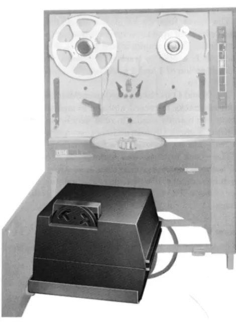
Tape Punch
The tape punch is housed below the tape reader in the
IBM 1621 (Figure 7) and punches data from core
[image:13.619.68.297.401.712.2]TRACKS
EL _ _
,..-J---, A BCDEFGH I J K L M N OPQRST U VWXYZI234567890 ) • • (
·
-
-X _ _ _0
-CHECK_
8 _ _ _
FEED-4
2
-I ••
~:::-
I • • •.
. .
.
I.~;
•••
,
..
,
I~ ~ ·I~
I
i
.
.
:
1
;
I
' •
I
·
•• ••
:
•
•
•
•
..
•
.
.
.
:
I
I
:
i
•
Figure 6. Paper Tape Codes
•
•
•
:
I
··
.~• •
•
I
·
• •
•
I
i
I
:.
I
·
• •
I
;;
. .
• • •
. .. . .
• •
.
.
1
;
1
; •
:~
.~•
~I;
1,1.
•
••
I
-
•
I'
second. The characters are sent serially from core
stor-age. starting with the locatio'n addressed by an output
instruction. Each character is translated into an 8-track code before being punched.
When a record mark is sensed during the execution of a Write Numerically or Write Alphamerically in -struction, an EL hole is pU'nched and the operation stops.
A Dump Numerically command causes punching to
continue, regardless of record marks, until the highes t-numbered core storage address of the 20,000 position
module addressed by the instruction is read and
Figure 7. Tape Punch Location
•
::
•
• •
•
I:
~
•
••
•
•
.I~I
:
.
.
~!• • •
;:
•
~~ !~I
I
:·
; •
.
•
.
...
•
1
:
1
:
! ..I!
••
.
~
•
I
'
I
-
e
•
•
•
punched. At this point an EL hole is punched and the operation stops. If a character with incorrect parity is
transmitted from core storage and punched, or a valid character is incorrectly punched, the tape does not ad-vance. Operation is the sam regardless of the position of the I/O Check switch on the 1620 console.
Tape Punch Error Procedure. The tape feed does not
advance. The computer stops; the Automatic and I fan -ual lights and the Write Interlock and Write Check
lights on the 1620 console are turned on. Program processing can be resum d with the following "restart" procedure:
1. Position the PU'nch Feed switch 0 .
a. The feed code is punched over the incorre character. If the instruction is Write Binary
paper tape, an EL character is also punched
b. The Write Interlock and Write Check lights are turned off.
c. Th machine is returned to manual mode only 2. Press the Start key on the 1620 console.
a. The original character from storag is again punched. If an incorrect character still e.ersists
the record may be corrected, if desired, befor processing continues.
b. The computer continues processing.
If the-Tape Punch is used in a 1710 Control System, and the I/O Check switch is positioned to PROGRAM.
the computer can branch to an error-handling routine. This routine can record the fact that a'n error has oc-curred and the computer resumes operation with the
incorrectly punched character in paper tape. If the Tape Punch runs out of paper tape, the ma-chine stops in automatic mode and the Write Interlock light is turned o'n. Machine operation may be resum d
by loading a new roll of tape and using the "restart" procedure just described.
[image:14.618.50.285.394.715.2]1. Use the SIE key to execute one instruction at a time.
2. When the Write Check light js turned on, observ the MBR display to determine jf the character is
valid.
A transi nt condition may cause the Write Check
light (but not the Write Interlock light) to come on
even though a valid character has been correctly
punched. Should this occur, turn on the Punch F ed
switch brieRy to turn off th Write Check light, then press the console Start key and proceed with the pro -gram.
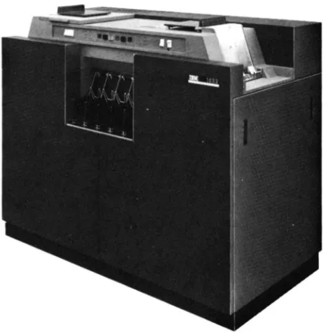
Card Read-Punch
The IBM 1622 Card Read-Punch (Figure 8) provides
punched card input and output for the system. The
reader and punch feeds are separate and functionall independent, with individual switches, lights, checking circuits, buffer storage, and instruction codes. nder program control, up to 250 cards per minut (cpm)
can be read and 125 cpm punched in the .fod I 1; the
Model 2 reads at 500 cpm and punches at 250 cpm.
Reading, punching, and processing can occur simul -taneously because of individual buffer storage. Buffer
storage data is transferred in 1.7 ms (Figure 9). A Last Card indicator (09) is provided for end-of-job interro· gation by the programmer.
Figure 8. IUM 1622 Card Read-Punch
Punch
1250r250
Output Buffer
1.7 milliseconds
.. ,"
Core Storage
Figure 9. 1622 BufTer Storage
Data Transfer
Read
250 or 500 cords per minute
Input Buffer
"t'
\(
.
;,~;
c
For numeric and alphameric input/output instructions,
data is transferred between 1620 core storage and 1622
buffer storage in blocks of BO or 160 digits without consideration of record marks. A full BO columns of
card data are always transferred. Buffer storag to core storage and core storage
to
buffer storage transfers re-quire 1.7 ms whether numeric or alphameric transfers are involved. When the highest-numbered core storage address of a 20,000-digit module falls within the trans -fer, core storage locations in the next highest 20,000 module are used or a "loop-back" to location 00000 occurs.
Card Coding
Record marks and blank columns are processed in the
follOWing manner:
Record Marks ( ). Card columns punched 0-2-8
are read into core storage as record marks, with either a Read Numerically or a Read Alphamerically instru
c-tion. Record marks are handled as data on both input and output and do not end the transfer of data.
A negative record mark (~), cod d X-B-2, is plac d in core storage as F-8-2, and punched X-8-2 in an out
-put card.
Blank Carel Colu.mns. Because blank columns are
[image:15.613.64.298.462.704.2]-not be punched in the card as blanks with a Write Numerically instruction. Therefore, cards especially punched 8-4 in all columns must be read into core stor-age to be used when blank columns are required in out-put cards. The 8-4 punches are stored as C, 8, and 4 bits, and are decoded as numeric blanks when transferred to output buffer storage.
By programming, the C, 8, and 4 bits (format blanks) are read into, or transmitted to, the output area of core storage. The output data is then transmitted into this 80-column record of blanks, leaving only the blanks required. The write instruction follows.
Double Punch Detection
Double punches are detected only if there is a dupli-cation of BCD bits. For example, a nine (8, 1) punch and an eight (8) punch in the same column are detected as a reader check because of 8-bit duplication. However, a six (4, 2) punch and a one (1) punch in the same column are read without error as a seven (4, 2, 1) be-cause there is no bit duplication.
BCD Coded Data
It is possible to read data recorded on IBM cards in Binary Coded Decimal form directly into the 1620 Data Processing System from the 1622 without first transforming the data to decimal codes. The BCD code5 shown in Table 1, are translated without read checks or parity checks. However, if the 12 punch is used for positive indication, the'll the 8, 2, 12 combination results in a flagged record mark (=*=). All other BCD card punches result in core storage values independent of a 12 punch, i.e., 4, 1, 12 gives 5.
Table 1. Valid Codes with Read Numerically
Positive Numbers Negative Numbers Card Core Storage Card Core Storage Punches Value Punches Value
1 1 1, 11 (or X punch) 1
2 2 2, 11 2
2, 1 3 1, 2, 11 3
4 4 4, 11 4"
4, 1 5 4, 1, 11 5 4, 2 6 4, 2, 11 6
4, 2, 1. 7 4, 2, 1, 11 'j
8 8 8, 11 8"
8, 1 9 8, 1, 11 9
8, 2
*
(RM) 8, 2, 11*
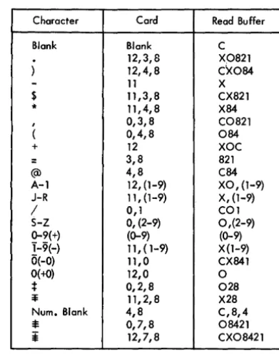
(RM)When a card is read by the 1622, the data is stored in the buffer in BCD notation. For example, if a 1 and 8 are punched in the same column of the card, they are
stored in the buffer as a 1 and 8, which is the BCD coding for a 9. (Note that a 9 punch also produces a 1 and 8 code in the buffer.) Zone punches in the card are also converted to the appropriate BCD coding. Thus, an X, 1, 4 punched in a column is stored as an "N" in BCD. BCD buffer codes are shown in Table 2.
Table 2. Character Coding Chart
Character Cord Read Buffer
Blank Blank C
12,3,8 X0821
) 12,4,8 C~084
-
11 X$ 11,3,8 CX821
* 11,4,8 X84
, 0,3,8 C0821
( 0,4,8 084
+ 12 XOC
= 3,8 821
(Q) 4,8 C84
A-1 12, (1-9) XO, (1-9) J-R 11, (1-9) X, (1-9)
/ 0,1 COl
S-Z 0, (2-9) 0,(2-9) 0-9(+) (0-9) (0-9) 1-9(-) 11,(1-9) X (1-9) 0(-0) 11,0 CX841
0(+0) 12,0 0
; 0,2,8 028
~ 11,2,8 X28
Num. Blank 4,8 C,8,4
*
0,7,8 08421*
12,7,8 CX08421The data transferred to core storage is under control of the Read instruction, A Read Numerically instruc-tion reads the X, 1, 4 into core storage as a flagged five ( 5). A Read Alphamerically instruction reads the X 1, 4 into core storage as a fifty-five (55).
Card Load Routine
A card load routine is described in Appendix E, Pro-gram Load Routines.
Printer
The IBM 1443 Printer (Figure 10) is an on-line output unit for the 1620 Data Processing System. Standard features include a tape-controlled carriage for trans-porting continuous paper forms, an interchangeable type bar, and buffer storage.
[image:16.621.303.499.196.447.2]The printer buffer enables the computer to transfer
core storage data to the buffer and then continue
processing during the relatively slow pri'nting
opera-tion. Printing speed is from 150 to 600 lines a minute,
depending on the 1443 Model and the character set of
the bar in use. A standard print line cO'nsists of 120
character positions. An additional 24 character posi
-tions are available as a special feature for each line.
Printing Operation
The 1443 type bar can print the standard 1620 char
-acter set, i.e., each of the 120 or 144 print positions can
pri'nt anyone of 48 different characters: 26 alphabetic,
10 numeric and 12 special characters:
Horizontal spacing is 10 characters to the inch. Vertical
spacing of six or eight lines to the inch is manually selected by the operator for continuous line printing.
Selective spacing a'nd skipping between printed lines
are controlled by the 1620 program.
Figure 10. IBM 1443 Printer
Several repetitions of the full character set are
lo-cated on the type bar. There are 120 or 144 hammer
magnets. and print hammers, each of which has an
indi-vidual print buffer position. Once the print buffer is
loaded, individual characters are printed as quickly
as they pass in front of the hammer that has the
corre-sponding character stored in that buffer position.
Printing Speeds
The 1443 Model 1 prints from 150 to 430 lines a min
-ute; the Model 2, from 240 to 600 lines a minute. The
determining factor for both models is the size of the
type bar character set:
Character Lines Per Minute
Set 1443-1 1443-2
13 430 600
39 190 300
-52 150 2<40
Print Control
Data to be printed must first be edited and arranged in core storage in exactly the format· to be printed. The appropriate 1620 output instruction can then be exe-cuted to transfer the data to the print buffer. The print buffer contains 197 positions even though the 1443 prints only 120 or 144 positions. The Printer Dump ( PRD-35) instruction transfers a full buffer load of
data, .197 characters, including group mark (=$=) and
record mark (=1=) characters. The Print Numerically
and Print Alphamerically instructions, however, trans-fer a full buftrans-fer load only if neither of the forenamed characters is detected. The detection of either character terminates data transfer and reduces the remaining buffer positions to blanks. Neither the terminating record mark nor group mark is transferred to the buffer. When performing a Print Alphameric operation, a group mark or record mark should be placed in posi-tion 121 or 145 to prevent possible Printer Checks caused by the transfer of the unedited positions (121 through 197 or 145 through 197) to the print buffer.
The Print Numerically instruction encodes and trans-fers single-digit characters. The Print Alphamerically instruction changes two-digit characters into single-digit characters before transferring them to the buffer.
Disk Storage
Data Code Structure
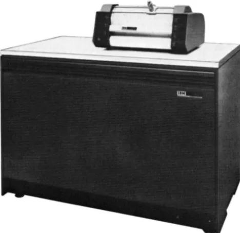
The IBM 1311 Disk Storage Drive serves as auxiliary
storage and is under direct control of the 1620 Central Processing Unit. Data is written· on the disks or read from them by means of program instructions stored in the processing unit, in much the same way as in
other I/O units.
The 1311 uses the 7-bit, BCD code as do many other
IBM systems. Encoding and decoding necessary for
conversion of the 1620 6-bit code and the disk storage 7-bit code are done automatically. All disk storage
read-ing and writread-ing operations are done in the numeric
mode. Data that is in the 2-digit alphameric mode in core storage must be written in disk storage in the
same 2-digit representation. If desired, the numeric
data in this alphameric code can be converted to I-digit form for transfer to disk storage and then converted back into 2-digit form after the data has been read back into core storage. The following instructions allow these code conversions to be accomplished as part of the regular program.
Transfer Numeric Strip (alphameric to numeric) Transfer Numeric Fill (numeric to alphameric) Move Flag (adjustment of field definition)
Other IBM systems record alphameric data in disk
storage in a I-character mode. If alphameric data from
these systems is to be used at a later time on a 1620 System it must be translated to the 2-digit alphameric representation before being entered into the 1620
System.
One additional special character is necessary in disk
storage operations; The group mark (=¥). Group mark
coding in various elements of the 1620 Data Processing System with identification of the same symbol in the 1400 Systems is as follows:
=1=
(Unflagged):$=
(Flagged)1620 Core Storage 1311 Disk Storage
Paper Tape I/O
Typewriter I/O
Card I/O
1440/1401/1410
C 842 1
o
8 421o
8 421$
0, 7, 8 Tape
Seg-ment Mark
F 8 4 2 1
CX08421 X 8 421
$
12, 7, 8 Group Mark
Use of the Group Mark is explained under DISK STORAGE
DATA PROTECTION. Sector Addresses
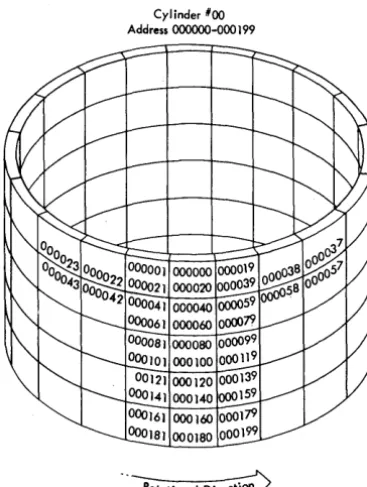
The 5-digit sector address is sequential from 00000-19999,20000-39999,40000-59999,60000-79999, or 80000-99999 within each disk storage module.
In the 00000-19999 sequence, sectors 00000-00019 are on the outermost track (cylinder 00) of the top re-cording surface (read/write head 0), Figure 11. Sec-tors 19980-19999 are on the innermost track (cylinder
Cylinder *00 Address 000000-000 199
[image:18.618.303.487.455.699.2]99) of the bottom recording surface (read/write head 9). Using the sector address, the 1620 automatically selects the correct drive, cylinder, and read/write head.
NOTE: Six-digit sector addresses are provided in the 1311 Disk Storage Drive, although only five positions are required in the 1620/1710 Systems. During all seek-ing, readseek-ing, or writing operations, the internal cir-cuitry of the 1620 Central Processing Unit
automatic-ally supplies a high-order 0 (zero) to all addresses; no
additional programming effort is necessary. Through-out this publication, sector addresses are referred to as consisting of only five digits.
Instruction Format
The format for disk storage instructions (Figure 12) is the same as for other 1620 operations and consists of a 2-digit Op code, 'a 5-digit P address, and a 5-digit
Q
address.P Address
Address of Disk Control f.ield
Figure 12. 1311 Instruction Fonnat
Q Address
The functions of the P and
Q
parts of the instructiondiffer from those of other input/output instructions. The P address, instead of being the core storage address
of the data transferred to or from the I/O unit, is the
core storage address of the disk control field, which is
described in the next section. The P address must
al-ways be an even number.
The
Q
part of the instruction must contain 07 inQR-Qn
to identify it as a disk storage operation, andmust contain a code in
Ql1
to define a particularfunc-tion within the regular Read Numerically or Write Numerically operation. The general areas of function definition are as follows:
1. Read or write a specified number of data sectors.
2. Read or write one full disk track, both data and sector addresses.
3. Read data from disk storage and compare it with the data in core storage from which it was written.
4. In any of the above functions, the
Qll
code alsospecifies whether or not the correct length of the record read or written is checked.
Disk Control Field
The disk control field is a 14-digit field that specifies the disk address where the data is to be read from or written to, the disk storage drive to be used, and the number of sectors to be read from or written to (Figure 13). The number of positions in core storage reserved for the data field must be large enough to contain all the data read from the disk. The total length of the area re-served for data can be defined by a group mark at the end of this field.
DRIVE CODE
X X
SECTOR ADDRESS
X X X X
Sector Address
00000-19999 20000-39999 40000-59999 60000-79999
SECTOR COUNT
X X X X
CORE ADDRESS
X X X X
Core Address
00000- 19999 00000-39999 00000-59999
80000-99999~ _______ -.
Figure 13. Disk Control Field
The sector address contains the disk address of the
data to be read or written. If more than one sector is
read or written, the address of the first sector is speci-fied.
The disk address of the data indicates which storage
drive is to be used by the system for an instruction (if
more than one is installed on the system). For example:
ADDRESS BLOCK
00000-19999 20000-39999 40000-59999 60000-79999
SELECTS DISK DRIVE
o
1 2
3
If the disk addresses on a disk pack do not correspond
to the number of the disk storage drive on which they are located, then the drive code is used.
DRIVE CODE
Selection of a particular disk storage drive can be made by using the following codes:
DRIVE CODE I 3
5
7
SELECTS DISK DRIVE NUMBER
o
I 2 3
For example, if address block 20000-39999 is located
on Disk Drive 3 (instead of Disk Drive I), the drive
code in the disk control field would be specified as
7.
When this Bexibility is not required, the drive is selected directly from the sector address and a 0 (zero) is placed in the drive code portion of the Disk Control Field.
The selection of a disk storage drive by either a drive code or a sector address is summarized in the chart below.
DRIVE CODE or ADDRESS RANGE SELECTS DRIVE
I 00000-19999 0
3 20000-39999 I
5 40000-59999 2
7 60000-79999 3
The eHect of using an invalid address or drive code, or using an address or drive code that specifies a non-existent drive, depends upon whether only o'ne drive or several drives are attached to the system. (An invalid address or drive code is any code not specified in the preceding chart. An example of addressing a
non-existent drive would be addressing a fourth drive 0'11
a system when the system contains only three.)
Single Disk Drive System. If only one disk storage drive is attached to the system, the drive code has no significance; the drive is addressed regardless of the digit in the drive code or the range into which the sector address falls. Also, in a single drive system, the range of addresses is not limited to 00000-19999; any range of disk storage addresses between 00000-99999 can be used.
Multiple Disk Drive Systems. If an address and/or drive code used in a read or write operation addresses a nO'n-existent disk drive, the computer is interlocked. The SCTR CYC light (under the I/O lights) a'nd the Write
Interlock light turn on. A seek operation to an invalid
address or to a non-existent drive does not result in an
interlocked condition; i'n this case, an error is detected during the following read operation by the address compare feature.
SECTOR ADDRESS
The sector address identifies the first sector of a disk operation. At the beginning of the operation, the sector address is transferred to OR-1 which is incremented
by one as each sector is
proce~sed.
Thus, at any timeduring a disk operation OR-1 contains an address one number higher than the current sector address;
how-ever, the disk control field in core storage still contains
the address of the first sector processed. Instructions i'n the track mode are exceptions to the above; none of the sector addresses are compared.
SECTOR COUNT
This is the number of sectors read or written. At the beginning of the operation, the sector count is
trans-ferred to PR-2, which is decremented by one before
each sector is processed. The operatio'n is terminated when the sector count reaches 000. At any time during
a disk operation, the number in PR-2 is one less than
the number of sectors yet to be processed, and the sec-tor count in the disk control field has the total number of sectors in the operatio'n.
CORE ADDRESS
This is the 1620 core location of the leftmost position of the data transferred to or from disk storage. The core storage address of a disk storage record must be an even number. At the beginning of read, write, and check disk operations, the core storage address is put in OR-2 and incremented by two for each succeedi'ng position addressed. The original address relpains in the disk control field.
Disk Storage Data Protection
Two safeguards, controlled by programming, are in-corporated into the 1311 Disk Storage Drive to prevent incorrect reading a'nd writing of disk storage data.
READ-ONLY FLAG
A Bag in the high-order (leftmost) position of the sec-tor address recorded on the disk permits the secsec-tor to be read only. An attempt to write in the sector (with the exception of a write disk track operation) results in an address check and termination of the operation. The Address Check i'ndicator (36) also turns on.
WRONG-LENGTH RECORD CHECK
To enable a record to be checked for the correct length, a group mark must be placed in core storage in the position following the end of the record. The data transfer is made with a Read, Write, or Check Disk instruction, and is modified to verify the length of the record by checking the position of the group mark and
the sector count in PR-2. If the group mark and a sector
count of 000 do not coincide, the operation terminates and the Wrong-Length Record/Read-Back Check in-dicator (37) turns on.
Programming Operations
The 1311 Disk Storage instructions consist of four ha"jc operations.
Seek Disk Read Disk Write Disk Check Disk
The read, write, and check disk operations can be
varied to operate only upon the data from the disks
or to utilize both data and the sector address in disk
storage.
BASIC OPERATIONS
Seek Disk. The seek disk operation directs the read/write heads to the proper cylinder on the disk pack. It is followed by a read or write instruction.
The data on the disk records is not acted on by this instruction. The seek instruction merely positions the access arms over the proper cylinder. The P address of this instruction contains the core storage address of the disk control field.
Read Disk. The read disk operation transfers data from disk storage to core storage in the processing unit. The area in core storage where the data is to be placed must be defined prior to the instruction. The P address of the instruction contains the core storage address of the disk control field.
Write Disk. The write disk operation transfers data from core storage to disk storage. The area in core stor-age from where the data is to be transferred must be defined prior to the instruction. The P address of the instruction contains the core storage address of the disk control field.
Check Disk. A Check Disk instruction should follow each Write Disk instruction. The check disk operation
causes the data written in disk storage to be read and
compared with the original source data in core storage.
When the disk data does not compare, bit-by-bit and character-by-character, with the data in core storage from which it was written, a disk error indicator is set.
TRACK AND SECTOR MODES
Read, Write, and Check Disk instructions have two "modes" of operation: track mode and sector mode.
Track Mode. The track mode of operation transfers
both data and disk sector addresses to and from disk storage, one complete track at a time. This mode of operation allows sector addresses recorded in disk stor-age to be changed. The operation requires that the disk control field contain an address of one of the sectors within the track. Sector count is set to 020 (twenty sectors are transferred).
Sector Mode. The sector mode is the normal mode of operation. Read, write, and check disk operations in the sector mode transfer data, but do not transfer disk sector addresses. The number of sectors to be handled within one operation is designated in the sec-tor count· portion of the disk control field. A secsec-tor is transferred only when the sector addresses in disk stor-age compare absolutely with those in the disk control field. The sector address in OR-l is automatically in-creased by 1 for each sector transferred and thereby supports the comparison of successive sector addresses. Similarly, the sector count is reduced by 1 for each sector transferred, and indicates by a 000 setting that
the required operation has been completed. .
Plotter
The IBM 1627 Plotter (Figure 14) converts tabulated
digital information into graphic form. Bar charts, flow charts, organization charts, engineering drawings, and maps are among the many graphic forms of data which can be plotted.
The 1626 Plotter Control Unit is the interconnecting unit between the 1627 and the 1620 Central Processing Unit. The 1626 contains the translating and control circuits for the 1627 and serves as a stand for the 1627.
Operation
Data from 1620 core storage is transferred serially (by digit) to the 1626 where it is translated into 1627 actuating signals. These signals are then converted into drawing movements by the 1627 Plotter.
Figure 14. IBM 1627 Plotter
The drum and the pen-carriage are bi-directional;
i.e., the paper moves forward or backward, and the
pen moves left or right. Control is also provided to
lower or raise the pen to or from the paper surface.
The pen remains in the "up" or "down" position until directed to change to the opposite status.
The drum and pen-carriage movements and the pen
status are controlled by digits transferred to the 1626
Plotter Control Unit by a 1620 Output instruction.
Each digit is decoded into a directional Signal and r
e-layed to the 1627 Plotter.
The plotter operation is controlled by any of the following instructions:
Dump Numerically
Write Numerically
Write Alphamerically.
Chart Paper
Pen and Carriage
Pen Notion
Figure 15. Paper and Pen Motions
Supply Spool
[image:22.616.37.271.72.299.2]Stored Program Concept
The 1620 CPU is a stored program computer, that is, it
stores and executes its instructions internally. The com-puter can perform distinct operations such as adding, subtracting, multiplying, comparing, branching, and so
on. It is directed by an instruction placed in core
stor-age to perform a specific operation. The programmer can select the most suitable operations, from the vari-ous computer operations available, to solve a problem or process data. A group of instructions representing
the operations to be performed is called a program.
Once the program is placed in core storage, the com-puter can be directed to execute automatically the instructions composing the program. Normally, the pro-gram is executed in a sequential manner, that is, the computer starts with the first instruction and progresses, in sequence, through the program, interpreting and ex-ecuting each instruction. However, this sequence of operations can be altered by the use of instructions that may direct the computer to an instruction located some-where other than the next sequential position.
Instruction
Characteristics
The 1620 uses a 12-digit machine language instruction divided into three parts: a 2-digit operation (Op) code,
a 5-digit P address, and a 5-digit
Q
address. Aninstruc-tion as it appears in core storage may be divided into
0, P, and
Q
subscripted numbers, as follows:In contrast to a data field, which is addressed at its rightmost digit and read from right to left, instructions
are addressed at 00 , the leftmost digit, and read from
left to right.
1620 Instructions
Op Code
Upon initiation of an instruction, the operation code is placed in a 2-digit Op register and is analyzed to determine the operation to be performed. The address
of an instruction must always be even; that is, the 00
digit of an operation code must be stored in an even-numbered address so that the Op register can receive the correct digits.
P Address
The P address specifies: (1) the location to which data is transmitted, (2) the location to which the program branches, (3) the location from which data is trans-mitted (output instructions), (4) the location of the alphameric field in the Transfer Numerical Strip and Transfer Numerical Fill instructions, or (5) the ad-dress of a control word used in disk storage operations.
Q Address
The
Q
address specifies: (1) the location from whichdata is transmitted, (2) the indicator being
interro-gated, (3) the 110 unit being used, or (4) the location
of the numerical field in the Transfer Numerical Strip and Transfer Numerical Fill instructions. Also,
instruc-tion modifier digits are placed in the
Q
address forthese instructions with the same Op code number.
Instruction Execution Time
The time required to execute an instruction is divided into two parts: the Instruction (I) cycle and the Ex-ecution (E) cycle.
I Cycle. The instruction is read out of core storage into instruction registers for decoding. Since most in-structions have the same length (12 digits) I time is normally the same for all instructions; 60 pSec. There
are six 10-fLsec cycles in each· I cycle. A microsecond
-abbreviated as "fLsec"-is one millionth of a second.
E Cycle. The instruction is executed as specified by
its Op code and P and
Q
parts. The E cycle, which is theactual time required to execute the instruction after it has been read into the instruction registers, requires
instructions, size of data fields, speed of I/O units, etc. The formula for computing the total execution time follows the description of each instruction. Execution times for all instructions are summarized in Appendix A. The symbols used in the formulas are defined as follows:
Dp
=
Number of digits, including high-order zeros, in the field of the P address. DQ=
Number of digits, including high-orderzeros, in the field at the
Q
address. DQ'=
Number of digits, including high-orderzeros, in the data field of an immediate instruction.
Dz
=
Number of positions compared, prior to the detection of a digit other than zero. T=
Time, in p,sec unless otherwise noted.Additional symbols used only in Load Dividend, Load Dividend Immediate, Divide, and Divide Immediate instructions are defined under EXECUTION TIME, follow-ing the explanation of the individual instruction.
Immediate Instructions
Certain arithmetic, internal data transmissions, com-pare, and branch instructions are labeled "immediate." Immediate instructions use th.e digits in the
Q
positions of the instruction as data instead of using them as the address of data.Thus, the
Q
data is located immediately within the instruction. For example, when the Transmit Field Im-mediate instruction, 16 00543 18765, is executed, theQ
part of the instruction, 18765 is transmitted to the P address (Figure 16). Data transfer begins at Qll of the instruction, and continues until a flag bit is foundOP
Code P Address Q Address
Core Storage
Figure 16. Transmit Field Immediate - Data Flow
(Q7 in this case). If the flag bit was at QI0' 65 would be transferred to 00543. The difference between the Transmit Field and Transmit Field Immediate instruc-tions can best be shown by comparing Figures 16 and 17. The Transmit Field instruction, Figure 17, trans-fers the data at the
Q
Address to the P addresses.Indirect Addressing
Indirect addressing saves program steps and computer time by providing a simplified method of address modi-fication. Its primary use is in programs where many instructions have the same address and this address' must be modified by the program. Indirect addressing may also be used for linking subroutines.
Description
Normally, the P or
Q
address in an instruction is the location of the data used during execution of the in-struction. An indirect P orQ
address, however, is the address of a second address instead of the address of data. This "second address" is the core storage address of the data to be used, except if the second address is another indirect address. In effect, the address at the indirect address location is a substitute for the address of the instruction.The data field specified by the indirect address is always five digits in length. The upper digit of the address does not require a flag to define the field. More-over, its length is always five digits even though flag bits exist within the fleld.
The P or
Q
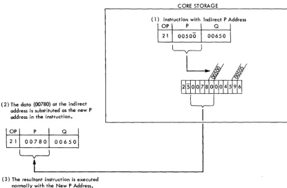
address ot an instruction is an indirect address when a flag bit is over the units positio~. Figure 18 shows that (1) the instruction (21 00500 00650) has an indirect P address of 00500, (2) the data atOP
Code P Address Q Address
1216!~'~
Core Storage
~
!";)&
2 9 4
~---""!~/~y
j612191411
~
I
CORE STORAGE
(1) Instruction with Indirect P Address
(2) The data (00780) at the indirect address is substituted as the new P address in the instruction.
(3) The resultant instruction is executed normally with the New P Address.
Figure 18. Indirect Addressing
OP
00500 is 00780, which is used as the P address during execution of the instruction, and (3) the instruction (21 00500 00650) is not altered in core storage; only an instruction register in the 1620 is changed.
The data at the location specified by the indirect
ad-dress is also -an indirect adad-dress if a flag bit exists in
the units position. This chaining effect continues until a flag bit does not exist in the units position of the ad-dress; this address is then treated as a direct address.
Any P or
Q
address of an instruction that specifiesthe location of data can be an indirect address. When the P -address of an immediate instruction is an indirect
address, the
Q
data cannot be more than six digits inlength because the flag bit over the units position of the P address also defines the end of the immediate data.
The Indirect Addressing feature can be turned off when programs not using the feature are being pro-cessed. Indirect addressing becomes operative auto-matically when power is turned on. Indirect address-ing can be turned off or turned on by the Branch and Select instruction.
Execution Time
Each address interpreted as an indirect address re-quires three additional 10-.usec memory cycles. For example, an instruction with two indirect addresses requires an additional 60 .usec.
EXAMPLES
The Add instruction, 21 00500 00650, is shown in
Fig-ure 19 with direct and indirect
Q
addresses. Line 1shows direct addressing; the
Q
data is obtained fromthe
Q
address. Line 2 shows theQ
address as indirect;the
Q
data is obtained from the address specified bythe indirect address. Line 3 shows that the address specified by the indirect address is also indirect; the
Q data is obtained from the address specified by the
second indirect address.
The data flow diagram for an Add Immediate
instruc-tion, 11 00500 00650, is shown in Figure 20. The
Q
data 00650, is added to the data at the ~ddress specified
by the indirect P address. The result 1155078, replaces the original P data, 1154428, at 09400.
[image:25.621.72.487.64.336.2]Instructions Data at Storage Locations
00650 15225 12500
Cl)2 I 00500 00650 15225
@21 00500 00650 15225 12500
@21 00500 00650 15225 12500 12345
Figure 19. Examples of Indirect Addressing
OP Code
err:
pT
Q~
500: 00650~
\ IY I
I
I
if
<::5 ~ \094001Resultant Modified Actual Q Actual Q
Instruction Address Data Used Used
00650 15225
2 I 00500 15225 15225 12500
(a)2 I 00500 15225
(b)2 I 00500 12500 12500 12345
CORE STORAGE
{§>I
),fj
III
54428~
(6 Digits Ncximum)
L
Adde,f-00065 I 15442 I 15507 0 8 8
Figure 20. Indirect Addressing, Add Immediate Instruction
1491005001000001 ~
The Op code for the new instruction is contained in core storage locations
16000 and 16001.
Figure 2L Indirect Addressing, Branch Instruction
CORE STORAGE
To Instruction Registers
Instruction Types
The description of the instructions are grouped into eight categories:
1. Arithmetic
2. Logic
3. Internal Data Transmission
4. Input/Output 5. Program Control
6. Floating Point (Special Feature) 7. Index Registers (Special F