PROGRAMMING THE IBM
PROGRAMMING THE IBM 1401:
A Self-Instructional Programmed Manual
JAMES A. SAXON WILLIAM S. PLETTE
Saxon Research Corporation United Research Services
PRENTICE-HALL. INC.
PRENTICF-HALL mTERNATIONAL,
nm. -
london PRENTICF-HALL OF AUSTRALIA, PrY., LTD. - Sydney PRENTICF-HALL OF CANADA, LTD. - TorontoPRENTICF-HALL FRANCE, S.A.R.L. - Paris PRENTICF-HALL OF JAPAN, mc. - Tokyo :I'RENTICE-HALL DE MEXICO, SeA. - Mexico City
© 1962 by PRENTICE-HALL, mc., Englewood Cliffs, N.J. All rights reserved. No part of this book may be re-produced in any form, by mimeograph or any other means, without permission in writing from the publisher.
Library of Congress Catalog Card Number: 62-20615
Printed in the United sta tea of America
To
Tottie
and
INTRODUCTION
This self-instructional work book has been developed to teach the beginner to program for the IBM 1401 computer. Programming simply means the ability to translate into language understandable by the computer, whatever we wish to have accomplished by the computer.
There is no time limit or speed limit imposed on the course. Each student will progress at his own rate of speed. If an area is not completely clear the first time through, it should be reviewed until there are no further questions in the mind of the student.
The correct answer to every problem is to be found on the back of the page' containing the problem. There is nothing to keep the student from cheating by looking at the correct answer before attempting to work the problem except the realization that he will not learn to program if he does this.
For best results, it is suggested that this book be studied for not more than two hours at a time and not more than two such (two hour) sessions a day. There is a great deal of material to be assimilated and attempting to push through too fast will cut down retention of material covered.
It must also be understood that completion of this work book will not qualify the student as an expert programmer. It will teach him the fundamentals of programming for the IBM 1401. He will have the basic tools of programming at his finger tips but only practical experience as a working programmer can develop the knowledge and skill required to be considered an expert.
As time goes on, computer manufacturers will continue to make advances and some of the limitations listed in this text will be exceeded, but as long as the 1401 Computer is used, the general information and programming methodology will be applicable.
TABLE OF CONTENTS
GENERAL INFORMATION UNIT I
LESSON
UNIT II LESSON
UNIT III LESSON
UNIT IV LESSON
UNIT V
1 2 3 4 5 6 7 8 9 10 11 12 13 14 15 16 17 18 19
LESSON 20 21
22
23 24 25
Computer Storage Computer Word • Word Marks • • • •
Data Words • • • • Instruction Word • • Instruction Use
Reserved Areas of Storage Basic Instructions
· ·
·
Input-Output Instructions Erasing Information·
Sample Program·
· · ·
Magnetic Core StorageData Transmission
·
Logical DecisionsAddition
.
. ·
· · ·
Subtraction· · ·
·
·
·
·
Miscellaneous Instructions Sample Program·
·
·
·
· ·
Chaining. . ·
·
· · ·
· ·
Symbolic Programming • • Symbolic Coding Sheet •• Constants and Work Areas • Assembling the Program • Character Adjusting • • Sample Program • • • • •
ix .
·
·
·
·
·
·
·
· ·
· ·
·
· ·
·
· ·
·
· · ·
·
· · ·
·
· · ·
·
· ·
·
· · ·
· ·
· · ·
·
·
·
xi 1 3 5 7 9 11 15 17 21 25 29 35 41 45 57 63 67 73 79UNIT VI
LESSON 26 27 28 UNIT VII
LESSON 29 30 31 UNIT VIII
LESSON 32 33 34 35 36 UNIT IX
LESSON 37 38 39 UNIT X
LESSON 40 41 42 INDEX • • • • •
Variations of Read, Print and Punch Editing and Arranging Printouts • • Printer Controls • • • • • • • • • • •
rJIultiplication Division
Address Modification
Magnetic Tape
. . ·
Writing on Magnetic. . .
Tape Reading from Magnetic Tape·
·
· · ·
· · · ·
· ·
· ·
·
Special Features of Tape Processing Read and Write Sub-Routines
·
Special Features
· .
.
.
Operating Steps. ·
Quick Reference and Fi.nalSystem Analysis • • • System Programming Final Problem • • • •
· ·
Quiz
·
· ·
·
·
·
·
·
·
. .
. .
TABLES AND ILLUSTRATIONS
x
I I I
GENERAL INFORMATION
Automatic Data Processing is the self-controlled sequence of actions by a computer, each action depending on another and requiring no human intervention to complete the sequence.
A Stored Program System is one that stores its instruc-tions internally. A sequence of instructions to solve a particular problem is called a program. The individual
instructions are called program steps. These program steps
are converted from writin~ to punched cards, which are loaded into the computer (placed into the Memory unit of the 1401). When data is fed into the computer, the stored program acts on the data to produce the desired result.
As a very simple example, let us assume that we wish to process a large number of punched cards and, among other things, every time we find a card with the digit
"5"
in column one, we will want to print out the contents of this card in a management report.Our stored program will contain an instruction that says, "Look for a
"5"
in column one." "If a"5"
is found, this card is to be processed to produce a printed report."As data cards are fed into the 1401 for process-ing, each card will be examined for a
"5"
in column one and the contents of the"5"
cards will be printed as desired.Nearly all data processing systems incorporate the fol-lowing five functions:
1. INPUT - This refers to anything that enters the system.
2. STORAGE - This refers to the data after it is read by the machine. It is held in storage until it is ready for use.
3.
CONTROL - This allows the machine to process the various steps specified by the program.4.
ARITHMETIC - This refers to the ability of the machine to perform arithmetic operations (i.e., add, subtract, multiply and divide).5. OUTPUT - This refers to anything turned out by the machine.
Program planning is one of the most important functions in programming. When it has been determined that a partic-ular function, or job, is to be handled by a computer in preference to manual methods of handling, the following steps must be taken:
1. Analysis of the job -- how it will be handled and what specifically will be involved.
2. Sequencing the steps to be taken to accomplish the basic purpose.
3.
Writing the instructions (program steps).4.
Determining which areas of storage will be used for various purposes.The ability to plan a job for computer application re-quires a knowledge of the machine components and functions and the instructions which cause the functions to occur. The greater the knowledge, the easier it is to plan and execute the required job.
Flow charting: Before writing machine instructions, it
is usual to flow chart the necessary steps to be taken. This has the advantage of proving the logic of the applica-tion since a flaw in logic will show up very quickly on a flow chart. It has the additional advantage of providing a chart from which machine coding (writing instructions for the program) may be accomplished with a minimum of error.
Symbols and signs have been fairly well standardized for flow charting purposes. The primary reason for this stand-ardization is so that others may easily read and interpret a programmer's flow chart. Some of the more commonly used signs and forms are shown on the following page.
COMMONLY USED FLOW CHART SYMBOLS
(
Q
D
o
C
____
)
D
0 0
o
-~~O
IBM PUNCH CARD - Denotes input or output data in 80-column cards MAGNETIC TAPE - Denotes input or
output data on magnetic tape PRINTED OUTPUT - Denotes output in a
printed form
START - Denotes the point at which a program begins
HALT - Denotes the point at which a program ends
PROCESSING
BLOCK - Fill with a brief
DECISION BLOCKS
description of each discrete process
- Denotes the point at which a program branch-es due to a decision SUB-ROUTINE- Represents a "program"
within the main program which may be flow-charted in detail elsewhere
DIRECTION
OF FLOW - Used to connect the other symbols
CONNECTORS - Used to show how the sections of the flow-chart connect together
This is IBM's solid-state 1401 data processing system.
It is available in four basic models: punched card, magnetic tape,
RAMAC (random access disk storage), and RAMAC/tape.
The 1402 card read punch (left) can read a maximum of
800 IBM cards a minute. The 1401 processing unit performs all
the arithmetic, logical and control functions. The IBM 1403 printer
prints numbers and letters at a basic speed of 600 lines a minute.
High-speed 729 magnetic tape units (right) are able to read as many
as 62,500 characters of information into the system in a second.
!
U NIT
Lesson 1
COMPUTER STORAGE: Storage, or memory, permits the computer to retain information, in a readily accessible form, until it is needed. The IBM 1401 may have 1400, 2000, 4000, 8000, 12000 or 16000 positions or cells of high speed memory. Each memory cell is capable of storing, sUbject to recall, any one of the decimal numeric characters lO through
9),
any alphabetic character (A through Z), or anyone of twenty special characters such as a period (.), comma (,), etc. Each storage position is numbered to simplify reference to it, starting with 000 and continuing to 1399, 1999, 3999, and up, depending on the size of memory of the IBM 1401 be-ing referenced. The number representing a storage position permits the programmer to address any specific storageposi-~ he may choose.
EXAMPLE: We wish to place the number 2749 into storage at positions 120 through 123. Assume that each position may be represented as a little box, large enough to hold one char-acter, and there are as many boxes as there are storage positions. After the correct instructions have been given to, and executed by, the computer the result may be repre-sented as follows:
12 1714191 120 121 122 123
PROBLEMS: Write your answers to the following questions in the space provided, referring as necessary to the text. After you have written and checked your answers, refer to the correct solutions on the following page. Do not proceed to the next lesson until you fully understand the questions and their correct solutions.
1. Place the digits ~ into storage at 1. positions 300 through 302.
2. Place the letter
E
into storage at 512. 2. 3. Place the word HOLD into storage at 3.positions 101 through 104.
4. If there are 8000 positions of storage 4. ( a) they are numbered from ~ to ~.
( b)
5.
When a programmer calls for a charac-ter from a specific cell in storage,he is that
ANSWERS
1. 1512171
300301302
2.
0
512
3.
I
HlolL
IDI
101 102 103 1044.
( a)000
( b)
7999
Addressing
UNIT I
Lesson 1
NOTES AND ANSWERS
REMINDERS
Each digit must be assigned to an individual memory position, each of which has an address number. Thus
2
goes into position300,
g
into301,
1
into302.
Alphabetic char-acters may be stored in individual, addressable memory cells in the same fashion.The first memory position is always numbered zero; therefore the last position must end in nine -- or one less than the memory size.
Just as a post office box number serves as a simple means of addres~
ing a particular box, the storage number serves as a means of addressing memory cells.
UNIT I Lesson 2
COMPUTER WORD: A computer word, as the term is used in con-nection with the IBM 1401, refers to a single character or a group of characters that represent a unit of information. An IBM 1401 word is not limited to a specific number of storage positions as in many computers. Computer words may be as long or as short as is actually needed to contain the
information in consecutive storage positions. The position
to the extreme left is called the high-order position of the word, and the position to the extreme right is called the low-order position of the word. Also, it must be remembered that every storage position in every word is addressable.
EXAMPLES: The number ~ occupying storage locations
421-425, might be considered a word if it is a single unit of information such as, "total number of employees". It would be pictured in memory as follows:
1
2131319151
421 422423 424425
The word STEP occupying storage locations 001-004 would be
considere~computer word pictured as follows:
Position 421 in the first the high-order positions. Position 425 in the first the low-order positions.
I
SITIElp I00 I 002 003004
example and
example and 001
004
in the second are
in the second are
PROBLEMS: Write your answers to the following questions in the space provided, referring as necessary to the text. After you have written and checked your answers, refer to the correct solutions on the following page. Do not proceed to the next lesson until you fully understand the questions and their correct solutions.
6.
7.
8.
Write the position numbers of the high-order characters in the following examples:
(a)ll,2,\4,51 6.(a) _ _
270 274
(b) _ _
( b ) M
Wri te the position numbers of 102103 (c ) _ _ _
the low-order characters in
the same examples. (c)IF,I,NIA,LI7.(a) _ _
406 910
A single character or group of characters (b) _ _ _
that represent a unit of information, is
called a ______________________ __ (c) _ _
8. ____ _
ANSWERS
6. (a)_..;;:2:...l..7~0 _ _
( b )_....;;;1;..;;,0.;;:;,.2 _ _
(c) 906
7. (a)_...;;:2:...l..7~4 _ _
( b ) _ _ 1,--0.0:,..3 _ _
(c) 910
8.
WORDUNIT I Lesson 2 NOTES AND ANSWERS
REMINDERS
The high-order position of the word is always the left-most
digit or position.
~he low-order position of the word is always the right-most digit.
A word may occupy as many con-secutive storage positions as are necessary to contain a unit of information.
UNIT I Lesson 3 WORD MARKS: The IBM 1401 is a variable word length compute~
This means that a computer word may be as long or as short as needed to contain a unit of information. The word mark makes variable word lengths possible. A word mark is not a character in itself, but is associated with the high-order
(left-most) position of a word. The word mark may be shown symbolically by underlining the character with which it is associated. The word mark tells the computer that the posi-tion so designated is the beginning of a word. When the computer senses another word mark, as it scans each charac-ter, it recognizes that a new word is beginning and that the previous word has ended.
EXAMPLE:
121912151~IEINID1115161li101LID111
101 102 103 104105 106107 108109 110 III 112 113 114 115 116
The storage positions shown above contain five computer words. The word marks in positions 101, 105, 109, 112, 116 indicate the beginning of each word. and PROBLEMS: Write your answers to the following questions in the space provided, referring as necessary to the text. After you have written and checked your answers, refer to the correct solutions on the following page. Do not proceed to the next lesson until you fully understand the questions and their correct solutions.
9.
1112131~131211IQI5IHI21115IsITluIYI~1
9. High Low 200201202203204205206207208209210211212213214215216217Indicate the high- and low-order positions of each word shown in the storage cells above.
10. Symbolically represent the word PRICE 10. in storage positions 501-505, placing the word mark in the proper position.
(a) _ _ _ _
(b) _ _ _ _
(c) _ _ _ _
(d) _ _ _ _
(e) _ _ _ _
(f) _ _ _ _
11. With respect to computer words, the 11. (a) __________ _ IBM 1401 is a (a) (b)
(c) computer. (b) _ _ _ _ _
(c) _ _ _ _ _
UNIT I
Lesson 3 NOTES AND ANSWERS
ANSWERS REMINDERS
9.(a)~~
(b)..1.Q.L ~
( c
)...1S2L
...nQ...(d).2lL ~
(e)~~
(f)....nL ....nL
10. lE,R,I,C,EI
501 505
11. (a) VARIABLE (b) WORD
(c) LENGTH
The word mark always indicates the
high-order position. The last two
words are only one character in length, therefore the single char-acter in each case is both the high- and low-order position.
The word mark should be associated with the P or high-order position.
Since a word may be of any length in the IBM 1401, it is called a variable word-length computer.
UNIT I Lesson 4
DATA WORDS: Data, as we refer to it in this text, means any computer word or group of words which are to be operated-on by the computer in some way. A data word is frequently re-ferred to as a data field, meaning a field of characters which might be descriptively referred to as a NAME, EMPLOYEE NUMBER, PAY-RATE, or TOTAL HOURS. A data field is always addressed by its low-order (right-mos~osition. Whenever the computer performs an operation on a data field, it be-gins with the low-order position and proceeds to the left, character-by-character, up to and including the position containing the word mark (W/M).
-EXAMPLE: If the word MAN was in storage at positions 901-903 and we wished to move it to positions 501-503, we would instruct the computer to: "MOVE 903 to 503," addressing the low-order positions of both words.
IMIAINI Ixlxlxl
I xlxlNI IxlAINI IMIAINI
901 902903 501 502503 501 502503 501502503 501 502503First the N would move from 903 to 503; then the A would move from 902 to 502; finally, the M would move from 901 to 501 and the word mark (W/M) in 901 would stop the move operation.
PROBLEMS: Write your answers to the following questions in the space provided, referring as necessary to the text. After you have written and checked your answers, refer to
~~~ correct solutions on the following page. Do not proceed to tn~ next lesson until you fully understand the questions and their correct solutions.
(a) IFILIIlpl (b) 11 1315171 6 1 12. (a)
225 228 004 008
131TI71
( b) (c) ( d) lsi TI 0lpi
202 204 205 208 ( c)
12. Write the storage position number to ( d) be addressed in each of the above.
13. Write the storage 1osition in which 13. ( a) the word mark (W/M should be placed
in each of the above. (b)
(c) (d)
ANSWERS
12. (a) 228
(b) 008
( c) 204
( d) 208
13. (a) 225
( b) 004
( c) 202
(d) 205
UNIT I Lesson
4
NOTES AND ANSWERS
REMINDERS
Data words or fields are addressed by their right-most or low-order positions.
UNIT I Lesson 5
INSTRUCTION WORD: The computer performs operations by
fol-lowing instructions prepared by a programmer. Each
instruc-tion specifies a specific operainstruc-tion and is contained in a computer word. The number of characters in an instruction word may vary from one to eight including up to four parts, depending on the nature of the instruction. The four parts are defined as follows:
OPERATION CODE 1 digit
A - ADDRESS 3 digits
B - ADDRESS 3 digits
DIGIT MODIFIER 1 digit
A code defining the operation to be performed. This code must always be present in every in-struction and must have a word mark.
The address of the low-order char-acter in a data field which is to be operated-on. In a MOVE instruc-tion, for example, the field from which data will move.
The address of the low-order char-acter in the second field, if any, to be operated-on. In a MOVE in-struction, for example, the field to which data will move.
This character, if present, usu-ally modifies the OPERATION CODE, making it possible to use the same OP CODE for several different but similar processes.
EXAMPLES:
~
A B d An instruction to move dataM
01 0 16 5151 6
from position
006
to position556.
M is the OPERATION CODE for MOVE.
006
is the low-order address of the data to be moved.556
is the low-order address to which the data is to be moved. This instruction does not require a data modifier, so none is present.PROBLEMS: Write your answers to the following questions in the space provided, referring as necessary to the text. After you have written and checked your answers, refer to the correct solutions on the follOwing page. Do not proceed to the next lesson until you fully understand the questions and their correct solutions.
14. Instructions may have ~ to ~
characters.
15. 16.
The W/M is always associated with the
(a) ( b ) .
There may be up to ~ parts to an instruction, but never less than
~.
9
14. (a) _ _ _ _
(b) _ _ _ _
15. (a) _ _ _ _
(b) _ _ _ _
16. (a) _ _ _ _
ANSWERS
14. (a) _ _ =l _ _
(b) _ _ S,--_
15. (a) OPERATION (b) CODE
16. (a) 4 (b) 1
UNIT I
Lesson 5 NOTES AND ANSWERS
REMINDERS
The number of characters in an instruction depends upon the kind of instruction and what it is to do.
The operation code must always be present and must have a W/M associated with it.
UNIT I Lesson 6 INSTRUCTION USE: All four parts of an instruction need not be used. Six combinations are possible:
1. OPERATION code, only. (OP) 2.
2. OPERATION CODE and DIGIT MODIFIER. (OP, d) 3. OPERATION CODE, A-ADDRESS. (OP, A)
4. OPERATION CODE, A-ADDRESS and DIGIT MODIFIER. (OP,A,d) 5. OP CODE, A-ADD, and B-ADD. (OP, A, B)
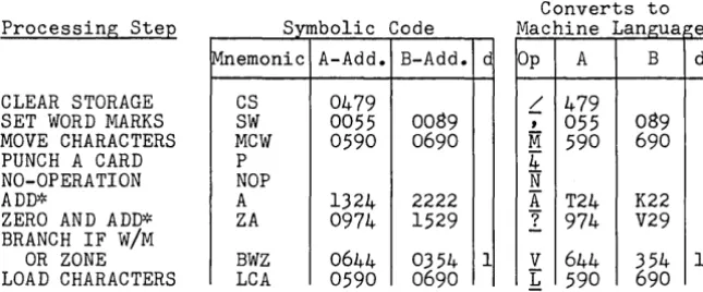
6. OP CODE, A-ADD, B-ADD, and DIGIT MODIFIER (OP,A,B,d) SPECIAL NOTE: A discrepancy may have occurred to you. Since A and B-Address spaces are 3-digit parts of the in-struction and storage addresses may be four or five digits long -- how can addresses higher than 999 be placed in the A or B parts of an instruction? This is accomplished by sub-stituting a special code for the first two or three digits of the address. This text will use examples for a 4000 position memory only - therefore a table of codes up to 3999 follows:
CODES FOR ADDRESSES IN STORAGE
Actual 3-Digi t Actual 3-Digit
Address Address Address Address
000 to 999 000 to 999 2500 to 2599 NOO to N99 1000 to 1099 =1=00 to *99 2600 to 2699 ¢OO to ¢99 1100 to 1199 /00 to /99 2700 to 2799 POO to P99 1200 to 1299 SOO to S99 2800 to 2899 QOO to Q99 1300 to 1399 TOO to T99 2900 to 2999 ROO to R99
1400 to 1499 UOO to U99 + +
1500 to 1599 VOO to V99 3000 to 3099 000 to 099 1600 to 1699 WOO to W99 3100 to 3199 AOO to A99 1700 to 1799 XOO to X99 3200 to 3299 BOO to B99 1800 to 1899 YOO to Y99 3300 to 3399 COO to C99 1900 to 1999 ZOO to Z99 3400 to 3499 000 to 099 3500 to 3599 EOO to E99 2000 to 2099 000 to 099 3600 to 3699 FOO to F99 2100 to 2199 JOO to J99 3700 to 3799 GOO to G99 2200 to 2299 KOO to K99 3800 to 3899 HOO to H99 2300 to 2399 LOO to L99 3900 to 3999 100 to 199 2400 to 2499 MOO to M99
Codes for positions higher than 3999 will not be needed for this text but may be obtained from the IBM 1401 Reference Manual.
UNIT I Lesson
6
(cont'd)
In the Codes for Addresses in Storage on page 11, you will notice that the third digit to the left contains a special character or alphabetic character. This character is placed in the hundreds position.
EXAMPLE: =t
I
9 9 1099HUNDREDS TENS UNITS
You will have noticed that the conversion from 2600-2699 is ¢OO to ¢99. The ¢ symbol is used to designate the alpha-betic
o.
If there is no slash through the 0, it is con-sidered to be a zero.Examples of the use o~ these special codes: 1.
S57
1257 2. M39 2439 3. ¢OO 2600 4. /22 =- 1122 5. D78 3478 6. 199 3999 7. <515 3015 8. R09 2909 9. Zll 1911 10. 55 1055UNIT I QUIZ 17. Place the word AREA into storage
at positions 901-904.
18. Write the position numbers of the high and low order positions in the following examples:
a. 15,6,7,81
001 004
b.
IJ,K,L,MI
220 223
c.
~
601602
19. In the above examples, write the position numbers where word marks should be placed.
20. In the above examples, write the storage position numbers to be addressed.
17.
18. high order a.
b. c.
low order a.
b. c. 19.a. b. c. 20.a. b.
c. _ _ _ _ _ _
21. If a word is to be moved from one 21.a. _________ _ place in storage to another, the ~
~ stops the move operation. b. _________ _ 22. Name the four parts of an instruction. 22.a. __________ _
23. The one part of an instruction that must always be present is the ~
-L'Q,L.
24. Write the following storage addresses in three digit code:
a. 0049 d. 2401
b. 1357 e. 2900
c. 2299' f. 3750
13
b. _______ _
c. _______ _
d. _ _ _ _ _ _
23. a • ________ _ b. _ _ _ _ _ _
24.a. _ _ _ _ _ _
b. _ _ _ _ _ _ _
c. ______ _
d. _ _ _ _ _ _
e. _ _ _ _ _ _
UNIT I QUIZ
ANSWERS REMINDERS
17. IAIR(EIAI Refer to page 1
901 904
18. high order low order a. 001 a. 004
b. 220 b. 222
c. 601 c. 602 Refer to page 3
19.a. 001
b. 220
c. 601 Refer to page 5
20.a. 004
b. 222
c. 602 Refer to page 7
21.a. word
b. mark Refer to page 7
22.a.
°E·
Codeb. A-address
c. B-address
d. digit modifier Refer to page 9
23.a.
°E·
b. Code Refer to page 9
24.a. 0~2 d. MOl
b. T57 e. ROO
c. K99 f. G50 Refer to page 11
UNIT I I
Lesson 7
RESERVED AREAS OF STORAGE: We have described the memory as being like a set of post office boxes, each capable of hold-ing a shold-ingle character. Some of these boxes are reserved
for specific purposes. They are:
Read Area: Positions 001 through OeO are reserved for in-formation coming into memory from punched cards. A "READ" instruction directed to the card reader will cause that machine to extract coded information, up to eO digits, from a standard IBM punched card and place the digits in corres-ponding memory storage positions. The digit in column one goes to storage position 001; column two goes to storage position 002, etc.
Punch Area: Positions 101 through leO are reserved for in-formation to be punched into eO column IBM cards. A "PUNCH"
instruction will cause all information stored in positions 101 to leO to be properly coded and punched into an IBM card.
Print Area: Positions 201 through 300 are reserved for printing. Thus up to 100 characters will form a single-line to be printed on the printer attached to the IBM 1401. A
"WRITE" instruction addressed to the printer will cause all the characters in positions 201 through )00 to be printed as a single line of information. (Some models of 1401 may be equipped with 132 reserved positions but the principle is the same. The printer will print all 132 positions on a single line.)
(READ AREA)
EXAMPLES: ( CARD
1->1
L. ~I~-L _ _ _ _ _ _ _ _ _ _ _ _ _ _ _ _ _ _ _ _ ~~~~080
(PUNCH AREA)
, 0 0 1
E3
1'----, - - - , I101 180
PRINTOUT ~ (PRINT AREA)
~I -,----~--~~----~,
I
201 300
PROBLEMS:
25. Information from a punched card going into 25.(a) ______ _
memory will always go into positions ~
through
..JE.L.
(b) _ _ _26. Each printed line will normally be characters long.
27. If a card is desired as output from the machine, the data must first be moved to
positions ~ through
..JE.L.
2e. Printing is always done from positions
-1al-
through ~ of storage, therefore,data must be moved there before giving
the instruction" (c) "
26. _ _ _ _ _
27.(a) _ _ _
(b) _ _ _
2e.(a) _ _ _
(b) _ _ _
ANSWERS
25. (a)_....;;;O...;;;;.O;;;.,l __
( b ) _....;;;O...;;;;.S..;;;.,O _ _
26. 100
27.(a) 101
(b) lSO
2S.(a) 201
(b) 300
(c) WRITE
UNIT II
Lesson 7
NOTES AND ANSWERS
REMINDERS
A knowledge of these reserved areas of storage is absolutely essential. They should be thoroughly memorized if they are not already firmly in mind.
UNIT II Lesson
8
BASIC INSTRUCTIONS: Each instruction is recognized in the machine by its one-digit operation code. In this and the lessons that follow you will learn these codes and, with the table given in lesson
6,
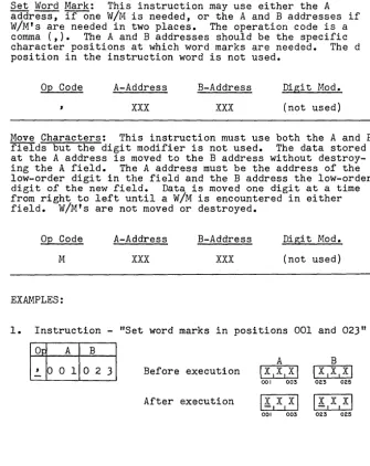
you will develop instruction words which will direct the computer's operation. The following are basic instructions:Set Word Mark: This instruction may use either the A address, if one W/M is needed, or the A and B addresses if W/M's are needed in two places. The operation code is a comma (,). The A and B addresses should be the specific character positions at which word marks are needed. The d position in the instruction word is not used.
Op Code A-Address
xxx
B-Address
xxx
Digi t Mod.
(not used)
Move Characters: This instruction must use both the A and B fields but the digit modifier is not used. The data stored at the A address is moved to the B address without destroy-ing the A field. The A address must be the address of the low-order digit in the field and the
B
address the low-order digit of the new field. Data is moved one digit at a time from right to left until a W/M is encountered in either field. W/M's are not moved or destroyed.Op Code A-Address
M
xxx
EXAMPLES:
B-Address
xxx
Digit Mod.
(not used)
1. Instruction - "Set word marks in positions 001 and 023"
O~ A B
A B
,
001o
2-
3 Before executionIx,x,xl
I
X,X,xl
00' 003 023 025
After execution
Ix,x,xl Ix,x,xl
00' 003 023 025
[image:31.441.32.367.158.580.2]UNIT II Lesson 8
(cont'd)
2. Instruction - "Set word mark in position 1250"
~
~
Before execution
After execution
Ixlxlxl
1250 1252
\xlxlxl
1250 1252 As shown in lesson 6, S is the code for 12nn.
3. Instruction - "Move four characters from positions 052-055 to 252-255"
A
o~ A B Before execution
M
°
5 5 2 5 5After execution
052 055 052
4.
Instruction - "Move three characters from 150-152 to 1350-1353 "A B
op
A B Before execution \11 0,MI
\~1716121
150 152 T50 T53
M
15
2 T5 3
After execution 11IO,M\ 1b:.ITIOIM\
150 152 T50 T53 The high-order position of the B-field is not affected since the first W/M encountered stops the operation.
5. Instruction ... "Move three characters from positions 027-029 to 301-303"
A B
Op A B Before execution 1112,3,~,5,6\1717171
024 029 301 303
M
°
2 9 3°
3After execution
1112131~15161~
024 029 301 303
6. Instruction - "Set word marks in positions 021 and 051"
A B
OQ A B Before execution
I
SI E ITI I
I II
021 023 051 053
,
°
21
°
5 1-
After executionI§.I E I T
I
I-I
II
021 023 051 053
UNIT II Lesson 8
(cont'd)
PROBLEMS: Write your answers to the following questions in the space provided, referring as necessary to the text. After you have written and checked your answers, refer to the correct solutions on the following page. Do not proceed to the next lesson until you fully understand the questions and their correct solutions.
Show how the memory positions would look after execution of each of the following instructions:
Instruction Before Execution After Execution
29.
~4 0 0 9 5 2
11121213141 12181716\
B
30. ~O 5 542 5 30.
I
1 1 1
051 055 422 425 422 425
IAIB1C1DI 111213141
B
31. ~ 0 0 502 5 31.
I
1 1 I
I
002 005 002 025 022 025
IX,Y,zl
A32.
,
o
2 5 32.c:=J
025 027 025 027
111313131
1~,41~,41
B
33. ~
J
o
9
5o
1 33.I
I I 1
JOG J09 498 501 498 501
~
IJ
IJ
IJ I
B
34. ~ 0 0 7 0 2 7 34.
c=J
007 025 027 025 027
B 12.161 181818181
35.
M
0 2 205 1 35.I
I
I
021 022 049 052 049 052
IH101L1DI
A
36.
,
001 023 ISIEITI 36.c=J
001 003 021 024 001 003
B
I
I 1I
021 024
ANSWERS B
29.
III
FI
II
ElL I D I947 952
B
30.
I
~,213141
422 425
B
31.
I!I
B, CI
DI022 025
A
32.
I
XI YIZI
025 027
B
33.
I
~,411131
498 501
B
34. I JI J IP
I
025 027
B
35.
I
Sl6 16 ISI
049 052
A
36. I§.I E I T
I
001 003
B
IHI°.1~IDI
021 024
UNIT I I
Lesson
S
NOTES AND ANSWERS
REMINDERS
The high-order position in cell 947 is untouched.
W/M in the B field stops the move.
A W/M in either the A or B field will stop character transmission.
W/M set in position 025.
First W/M stops the move.
W/M's are not transmitted to the B field.
Low-order position specified in B address was 051. Positions 049 and
052 unaffected.
W/M's set in the locations specified
by the instruction.
UNIT II Lesson 9
INPUT-OUTPUT INSTRUCTIONS: Means for getting data into
storage and out of storage requires a set of ir1,!-lut-output instructions. The simplest means of getting data into memory is to read a card which has been punched with the coded information. Cards may be punched by the computer with data developed during processing. Printed information may be supplied by directing the printer to print informa-tion stored in memory. The following instructions direct these operations:
Read a Card: This instruction causes the card reader to read
a
card transmitting the 80 columns of data to memory positions 001 through 080. Word marks are not disturbed. A or B addresses or the digit modifier are not needed.Op Code A-Address
1 (not used)
B-Address
(not used)
Digit Mod.
(not used)
Punch ~ Card: This instruction causes the card punch to feed a blank card which is then punched with the 80 charac-ters stored in memory positions 101 to 180. Word marks are not disturbed nor are they punched in the card.
Op Code A-Address
4 (not used)
B-Address
'( not used)
Digit Mod.
(not used)
Print (Write a Line): This instruction directs the printer to print the 100 characters stored in memory positions 201
to 300. Word marks are not disturbed nor are they printed.
(132 characters in some models.)
Op Code A-Address B-Address Digit Mod.
2 (not used) (not used) (not used)
NOTE: The Read ~ Card instruction will bring data into the reserved area without affecting word marks in the area. Therefore the programmer can set word marks in this area at the beginning of his program and not change them unless the size of fields in the cards change.
UNIT II Lesson 9 (cont'd) EXAMPLES:
1. A card is read into the read area. The information in Col. 1-5 are stored in positions 001-005. We want to punch a new card with the same information in Col. 11-15. Storage would look like this:
Read area ~~~~=~~~
____________________________
~,~I001 005 080
Punch area ~I ~'~I ________ ~~~~~~~~~~~ ______________ ~~'
I
101 III 115 180
To get the data from read area to punched card:
(a) Set W/M at 001
1~lo
0 11 Before 17 1\C 1D1EI After 11,5 I C I D, E I001 005 001 005
( b) Move data from read area to punch area
IMlo 0 511 1 51 Before Il ,5,C,D , EI After 17151C,DIEI 001 005 III 115 (c) Punch a card
[!]
All memory areas would be unchanged. Instruction2. Let us assume that in the same example we also wish to print the five characters but not together. We want to print the first two digits in print positions 4-5 and the last three digits in print positions 11-13.
(a) Set W/M's at 001 and at 003
1~lo
0 110 0 31 BeforeI
7 15,CIDIEI After 11151Q,D,EI 001 005 001 005 (b) Move data from read area to print areaIMlo 0 212 0 51 Before 11,5 1Q,D,EI After
~
Instruction 001 005 204205
I
M
10 0 512 1 31 Before 11 15 I Q I DIE 1 AfterI
C I DIE 1 001 005 211 213 Prin t area ... , ...r..' -L-J...,7-L,_5J.-1 _--JI'--C...r..1 D...rI_E....L, _ _ _ _ _ _ _-Jj
1,,--,--,-,--,
201 204205 211 213 300
UNIT II Lesson 9 (cont'd)
(c) Print data
All memory areas would be unchanged.
NOTE: When a card is read to memory Col. 1 will be stored in memory position 001, Col. 2 in position 002, etc. To punch in Col. 1 place the data in memory position 101, Col. 2 in position 102, etc. Simply add 100 to the desired column to obtain the memory address. To print in the 1st position of the print line store data in memory position 201, 2nd print position in 202, etc. Simply add 200 to the desired print position to obtain the memory address.
PROBLEMS: Write your answers to the following questions in the space provided, referring as necessary to the text. After you have written and checked your answers, refer to the correct solutions on the following page. Do not proceed to the next lesson until you fully understand the questions and their correct solutions.
In each of the following problems, show the locations in the reserved areas where data must be moved to achieve the de-sired result.
37.
38.
39.
40.
41.
42.
43.
Print in positions 85-90.
Punch in Columns 5-14.
Punch in Column 25.
Print in positions 25-34.
Punch an entire card exactly as it came in.
In problem 41 above show the move instruction required to move the data from read area to print or punch area.
In problem 40 show the "Set W/M" instructions required to control the movement of data.
23
37.
38.
39.
40.
41.
42.
ANSWERS
37. 290 3S. 114 39. 125 40. 234 41. ISO
42.
I
Mia
Sall
43.
I
~IO
251
S01
UNIT II
Lesson 9
NOTES AND ANSWERS
REMINDERS
Simply add 100 to any desired punch position
a-So
to get the punch-area address.Add 200 to any desired print position to get the print-area address.
It is usually best to set word marks in the read-area when the program begins and leave them as long as the fields within the input card are in the same positions.
UNIT II Lesson 10 ERASING INFORMATION: The following instructions erase in-formation from memory:
Clear Word Mark: This instruction, opposite to the set word mark instruction, will erase word marks from the memory
positions designated by the A and B addresses. The B address need not be used.
Op Code A-Address
xxx
B-Address
xxx
Dig. Mod. (not used) Clear Storage: This instruction will erase up to 100 posi-tions of memory. Clearing (erasing) starts at the position specified by the A-address and continues leftward down to the nearest 100's position. Word marks are erased when encountered.
Op Code A-Address
/
xxx
B-Address (not used)
Dig. Mod. (not used) Clear Storage and Branch: This instruction has the same Ope Code and performs the same as the Clear Storage instruction except that it has a B-address. When the B-address is pres-ent erasing begins at the B-address leftward to the nearest 100's position. Upon reaching the nearest 100's position the next instruction is taken from the memory position designated in the A-address.
Op Code A-Address
/
xxx
EXAMPLES:
B-Address
xxx
Dig. Mod. (not used)
1. Clear word marks from positions 001 and 005
I~IO
0 110 0 51 BeforeI!,B,C,D,~I
After IA,B,C,D,E\ Instruction2. Clear read area
Before After
UNIT II
Lesson10
(cont'd)
3.
Clear punch area and take next instruction from900
4.
Clear print area1
~13
0 01
/ 2 9 9
5.
Clear a storageI
LI6 7 51
6.
Clear word marks areafrom
Punch area
101-180
will be erased. The next instruction will be taken from900
rather than from the next word as would normally be true. NOTE: The branch instructionalways specifies the high-order or
QE
Code portion of the instruc-tion which is to be next executed.Print area
201-300
will be erased. The first Clear in-struction will erase position300
only and the second one will erase positions299
through
200.
Storage area will be cleared from position
675
down through position600.
positions
875
and1225
Word marks will be erased from the two indicated storage positions.
UNIT II
Lesson 10 (cont'd)PROBLEMS: Write your answers to the following questions in the space provided, referring as necessary to the text. After you have written and checked your answers, refer to the correct solutions on the following page. Do not proceed to the next lesson until you fully understand the questions and their correct solutions.
What would be the effect of the following instructions: 44.
Inio
5 11 Would clear what? 44.45. 1 LI5 2 01 Would clear which
storage areas? 45. 46.
I
LI3 3 21 Would clear whichstorage areas? 46. 47. 1 LI6 0 01 Would clear which
storage areas? 47. 48. 1 LI4 9 916 2 01
(a) Would clear
what storage? 48.(a) (b) Would branch to
where? (b)
49. tI 0 0 1
o
2 11 Would clear what? 49. 50./
J 9 9 Would clear whichstorage areas? 50. 51.
L
2o
0 Would clear whichstorage areas? 51. 52.
L
6 2 0 4 5 51(a) Would clear what storage
52. (a) areas?
(b) Would branch to
where? (b)
UNIT II Lesson 10 NOTES AND ANSWERS
ANSWERS
44. W/M at position 051
45. 500-520 46. 300-332 47. 600 only 48. (a) 600-620
(b) !±99
49. W/M's at positions 001 and 021
50. 2100-2199 51. 200 only 52. (a) 400-!±22
(b) 620
REMINDERS
The W/M would be erased at 051 without affecting the data. Erasing begins at the address specified and continues left-ward to the hundreds position which is also erased.
The Clear Storage and Branch has the "Clear" address in the
~ position and the "Branch" address in the! position.
UNIT II Lesson 11
PUNCHED CARDS: The two cards on this page show the holes punched to represent characters and the interpretation at the top of the cards. The first card shows the entire alphabet and the second card shows all numerics, the alpha-bet and special characters.
~BCD[FGH'~~LMNUPQkSTUYWXYZ 111111111
111111111
0000000000000000001111111100000000000000000000000000000 0 C d 0 0 0 0 0 0 0 0 0 0 0 0 0 0 0 0 0 00000
123451'11~11UU"'S"11"~mn~nH~an~~~~UUM~~ll»D~~U~"~~Uq~~~u~~~~~a9MUUUMU."UHm"nnUnnnnH.
11111111111111111111111111111111111111111111111111111111111111111111111111111111 212222222212222 n 212 2 2 2 2 2 2 2 2 2 2 2 2 2 2 2 2 2 2 2 2 2 2 2 2 2 2 2 2 2 2 2 22222222222222222222222222222 3313333333313333333133333333333333333333333333333333 3 3 3 3 3 3 3 3 3 3 3 3 3 3 3 3 3 3 3 3 33333333 4441444444441444444414444444444444444444444444444444 4 4 4 4 4 4 4 4 4 4 4 4 4 4 (4444444444444 5555155555555155555551555555555555555555555555555555 5 5 5 5 5 5 5 5 5 5 5 5 5555555555555555 S 6 6 6 616 6 6 6 6 6 6 616 6 6 6 6 6 616 6 6 6 6 6 6 6 6 6 6 6 6 6 6 6 6 6 6 6 6 6 6 6 6 6 6 6 6 6 6 6 6 6 66666666666666666666666 77777 717 7 7 777 7 717 77 77 77177 7 7 77 7 7 7 77 77 7 77 7 77777777 7 77 7 7 77 7 7 7 7 7 77 7 77 7 7 7 7 7 7 7 777777 7 8888888188888888188888881888888888888888888 a 8 8 8 8 8 8 88 8 8 88 8 8 8 8 8 8 8 8 8888888888888888 9999999919999999919999999199999999999999 9! 9 9 9 9 9 9 9 9 9 9 9 9 9 S 9 9 9 9 99999999999999999999
'2'411'11~11UU"~""U"annnH~auaa~~UU~~.ll ••• ~QQ"a.u.q~~~UMB~uaB.~UUMe.VA.~"nnU~"nnn.
-~
0123456789 ABCDEFGHI JKLMNOPQRSTUYWXY2
111111111
11111&111
II
100000 0 0 0 0 0 0 00000000000000000000011111111 0 0 0 0 0 0 1000 1000 led 0 0 00000000 0 GOD 0 0 0 0 0 0 0 0
12J.51'1'~IIUU"H""U"mnnnH3anan~~uu~~~n~n~~~u"a.uaas~uu~~~~a»YUU~MU.VAUn"nn"~nnnn.
11111111111111111111111111111111111111111111111111111111111111111111111111111111 2 212 2 2222222222212222222212222222122222222222222222222222 2 2 2 22 2 2 2 2 2 2 2 2 2 2 2 2 2 2 2 2 2 2 333133333333333331333333331333333313333333333311113333 3 3 3 3 3 3 3 3 3 3 3 3 3 3 3 3 3 3 3 3 3 3 3 3 3 3 444414444444444444144444444144444441444444444444441111444444444444(4444444444444 5555515555555555555155555555155 H 5 5 515 5 5 5 5 5 5 5 55555555555555555555555555555555555 666 &.& 616 6 6 6 6 6 6 6 6 6 6 6 616 6 6 6 6 6661666666616666666666666666666666666666666666666666 6 6 77 7 77 7717777777 7 7 77 7 7177 7 77 7 7 717 7 7 7 7 77177 77 7 7 7 717 7 7177 77 7 7 77 7 77177 7 7 7 7 117 7 7 7 7177
8888888818888888888888188888888188888881888888111111118 8 8 8 8 8 8 8 8 8 8 8 8 8 8 88888888888 999999999199999999999991999999991999999 91 ~ 999999999999 9 S 9 9 9 9 9 9 9 9 9999999999999999
12J451~:~:11UU"H"I,""aflnnU3anaa.n~uM~.n ••• ~uu"Q.nq"~~uUMBaua9U~UUMn.vuunnn»unnnnH.
UNIT II Lesson 11 (cont'd) A SAMPLE PROGRAM: A small manufacturing concern makes many different items. Each day the foreman fills out a sheet with information about the day's production. Each line on the sheet represents a different item. The sheet looks like this:
PRODUCTION REPORT
Part No. Part Name Number Man Labor Produced Hours Cost
674 WRENCH 16 5 28.90
684 FILE 20 4 24.00
692 HAMMER 41 11 65.60
698 SCREWDRIVER 20 7 41.70
This sheet is sent to a key-punch operator who punches the data into IBM cards; one card for each line of the report. She places the data in the following columns:
Columns 1- 3 Part Number
"
4-15 Part Name"
16-18 Number Produced"
19-21 Man Hours"
22-27 Labor Cost"
28-80 All left blankWherever a number has too few digits to fill the columns she punches zeros in the high-order positions. The card has data that looks like
this--67:?trlP.Ef-lr."H
I II
I; I
01601)5002890
00011,0000000000 0 I 00 110 11000 1000 0 0 0 0 0 0 0 0 000 000 00 000 0 0 0 0 0 0 0 0 0 0 0 000 0 0 0 0 0 0 0 0 0 0 0 0 0 0000
12'.5111'~IIUtl~~nlJ"n~nnnN~~nan~~u~~~»n~~~~~Q"~.nQU~~~~~~~~~"~~U~M~"Vwnro~nnunnnnn~
111111111111111111111111111111111111111111111111 111 11 I 11 11111111111111111 I 111111 2222222222222222222222212222222222222222222222222222 2 2 2 2 2 2 2 2 2 2222222222222222222 333333313333333333333333333333333333333303 3 3 3333333333333333333333333333333333333
44144 4 44 4 44 44 4 4 4 44 44 4 44 44 4 44 4 4 44 4 4 4 44444 4 4 4 44 4 44 44 4 44444444.444444444 44 44 4 44 44 44
55555115555555555555155555555555555555555555555555555 5 5 5 5 5 5 555555555555555555555 1661666666666666616666666666666666666666666666666666 6 6 6 6 666666666666666666666666 1111111 "1111117"1"1'11"""111""1'1""""'11""7'7'"111111111111111711 8 8 8 8 8 8 8 818 8 8 8 8 9 8 8 8 8 8 8 8 8 818 8 8 8 8 8 8 8 8 8 8 8 8 88888888888888888888 a 8 8 8 8 88888888888888888 99991999999999999999999991999999999999999999999999999 9 9 9 999999999999999999999999
12341111'WllU"W~""""mVnnN~~naa»~n»~~~n~~~~UQ"~.~ • • ~M~UK~SU.H.~aaMc.v • • ~nnnun~nnnm
UNIT II
Lesson.ll (cont'd)The accountant wants a card punched with the part number, the number produced and the labor cost in columns, as follows:
Columns II II
4- 6
10-12 15-20
Part Number Number Produced Labor Cost
The manager wants a printed list of all of the parts, by name, and the number produced, as follows:
Print positions 10-20 II " 30-32
WRENCH
FILE
HAMMER
SCREWDRIVER
Part Name Number Produced
016 020 041 020
We will write a program which will read each card, punch the cards for the accountant and print a list of items produced for the manager. First we will prepare a flow-chart showing each step to be performed in the computer.
The word marks are placed at the begin_} ning of the program and, since they are not destroyed, need not be placed again. The card must be } placed in memory at memory positions 001
to 080.
MOVE PART NO, Each data field must
l
NO. PRODUCEO be moved to itsAND LABOR COST proper place in the I-I_NT_O_P_UN.,-C_H_AR_E...JA punch area, memory ~
positions 101 to 180.
f
[
When the data is in } the punch area a card
is punched. \
MOVE PART NAME be moved to its
AND NO PRODUC. proper plac e in the
[
Each data field must)
TO PRINT AREA • \
~ __ ~ __ ~ pr1nt area, memory positions 201-300.
When the data is in } the print area a line
{
.[
of printing is ~
printed.
Clear the digits
}~
already punched out of the punch area. /.[
,I
Clear the digits already printed out} of the print area. Branch back to the read instruction to read the next card.
PROGRAM (The instruction
ad-dress tells where the instruction word is located in memory)
Op A B d
5
o
0-
' 001o
0 45 0 7
-
,
016 0225 1 4
1
5 1 5
M
o
0 3 1 0 65 2 2
M
o
1 g 112 5 2 911
o
2 7 1205 3 6
b:.
5 3 7
M
o
1 5 2 2 0544
11
o
1 g 2 3 2 5 5 1 ~5 5 2
/
1 g 0-556
/
514 299-Note: The last in-struction clears the print area and branches back to the instruction located at
514 which causes a new card to be read and the process is repeated.
This process will continue until the last card is read. when there are no more cards the computer will stop.
UNIT II Lesson 11 (cont'd)
PROBLEMS: Write your answers to the following questions in the space provided, referring as necessary to the text. After you have written and checked your answers, refer to the correct solutions on the following page. Do not proceed to the next lesson until you fully understand the questions and their correct solutions.
53. Input a card with the following data:
Card Col.
5-
$9-12 13-16 17-21
Description
Insurance Deduction
FICA "
Withholding Tax Total Deductions
Output a card with the following data:
Card Col.
1-
4
11-14 21-24 76-$0
Description
Insurance Deduction
FICA "
Withholding Tax Total Deductions
Write a program to read each card, move data to punch area, punch a card, clear the punch area and branch back to read again. Start your program at 500--and don't for-get to set word marks in the read area before reading.
54. Input a card with the following data:
Card Col.
1-19 20-22 25-39 40-44
Description
Salesman's Name Salesman's Number City
Total Sales
Print a line with the information as follows:
Print Position
20-39 50-54
Description
Salesman's Name Total Sales
Write a program to read each card, move data to print area, print a
INSTRUC. ADDRESS
5
o
0INSTRUC. ADDRESS 5
o
0line and branch to repeat. Start at 500.
33
Op A B
53.
54.
INSTRUC.
Op
A
ADDRESS
5
o
0-
,
o
0 5 5 0 7,
o
1 3 5 1 41
5 1 5
M
o
0 8 5 2 2 M 012 5 2 9MO
1 6 536M
021 543fr.
544
L
514INSTRUC·
Op A ADDRESS
5
o
0-
,
001 5 0 7 ' 0 2 55 1 4
1
5 1 5
MO
1 9 5 2 2M
o
4£0 5 2 9£
5 3 0
/
514-UNIT II Lesson 11 NOTES AND ANSWERS
B
o
0 9o
1 71 0 4 1 1 4
1 2 4 1 8 0
180
B
020 040
239 2 5 4
299
Set W/M's
If "
Read a card
Move Ins. to Punch Area Move FICA to Punch Area Move Tax to Punch Area
Move Deductions to Punch Area Punch a card
Clear Punch Area and Branch
Set W/M's
11 n
Read a card
Move Name to Print Area Move Sales to Print Area Print a line
*Clear Print Area and Branch to repeat
*Note that the "Clear n instruction will not clear posi-tion 300. If it is necessary to clear this position, a nClear" instruction should precede the final instruc-tion.
UNIT II Lesson 12
MAGNETIC CORE STORAGE: The IBM 1401 uses magnetic ~
storage for internally storing data and instruction. A
mag-netic core is a tiny donut-shaped bit of iron capable of being magnetized or de-magnetized by the direction of flow of an electrical current passing through it. When it is magnetized we may consider it to be "on" like a switch--when de-magnetized it is "off." Each storage position is com-posed of eight magnetic cores. A code made up of various combinations of these eight cores in "on" or "off" condi-tions tells the computer which character is stored at that position.
A storage position may be figuratively represented as follows:
W/MO
cO
BO
AO
80
40
20
10
}ZONE BITS
}NUMERIC BITS
The top ~, or bit, is "on" if this character has a W/M associated with it. The
Q
bit is used only by the computer as an internal accuracy check. The A and B bits are known as zone bits and the lower four bits are known as numeric bitS:--The numeric bits, singly or in combination, represent the digits from 0-9. The numeric bits, with one or the other or both zone bits added, make up the alphabet and special characters.EXAMPLES: When a bit is shaded, it is considered to be "on."
0 0 0 0 0
0 0 0
0 0 0 0 0
0 0 0 0 0
sO aO sO eO sO
40 40 40
4.
4.
20 2. 2. 20 20
I.
10I.
10I.
2 3 4 5
0 0
0
0 0
0 0
sO sO
s.
a.
s.
4.
2.
4.
40 40 402. 20 20 2.
10
I.
10I.
106 7 8 9 0
UNIT II Lesson 12 (cont'd)
Alphabetic Characters:
A through I - Both the A and B bits are "on," with numbers 1 through
9.
(A 1, B 2, C
= ),
D=
4,
E5,
F6,
G
7,
H 8 and I =9)
J through R - Just the B bit is "on" using numbers 1 through
9.
(J 1, K 2, L
= ),
M=
4,
N5,
06,
p7,
Q 8 and R=
9)S through Z - Just the A bit is "on" using numbers 2 through
9.
(S 2, T
= ),
U=
4,
V5,
W 6,
X7,
y 8, and Z
=
9)
Special characters such as the period (.), the comma (,), the slash
(I),
etc., are composed of various other com-binations of the zone and numeric bits.MAGNETIC OJRE PLANE
This close-up of a magnetic core plane shows some of the thousands of metallic. cDughnut-shaped cores that make up the central memory units of most electronic computers. The cores can be magnetized individually by energizing the tiny electronic wires on which they are threaded. Data is represented in each core by its "on" or "off" (magnetized or unmagnetized"
condition.
UNIT II Lesson 12 (cont'd)
PROBLEMS: Write your answers to the following questions in the space provided, referring as necessary to the text. After you have written and checked your answers, refer to the correct solutions on the following page. Do not proceed to the next lesson until you fully understand the questions and their correct solutions.
Since only six of the eight bits are used as coded versions of characters, the problems will only show six bits.
55. In the following symbolic representations of storage units, darken the bits to spell out
DEC25XMAS
wwwwwwwww
D E C 2 5 X M A S 56. Read the following storage units and place the letteror number each represents in the box below the figure.
m
;
00EB~
•[E;
•OJ;
•rn
i
•OJ:
0m
i
0o • 0 • • •
(0)
D
D O D D O D
ffiffiffirnEBmrn
(b)
D
D
D
D
D
D
D
57. If the zone bit was removed from the
letter "P" the result would be 57. _ _ _ _ _
58. If the zone bits were removed from the
letter "G" the results would be 58. _ _ _ _ _
59. If an A-bit was added to the numeric
115" the result would be 59. _ _ _ _ _
UNIT II
Lesson 12
NOTES AND ANSWERS
55.
ffiffiffiffiEBffiffiffiffi
D Ec
2 5 x M As
56. (a)
0 0
~
0 0 0
EJ
57. _ _ ...!...7 _ _
5$. _ _ ...!...7 _ _
59. _ _
~V _ _Remember that zone bits are used to indicate addresses
higher than 999~ Therefore
alphabetic and special charac-ters may appear in instruction addresses as a means of
desig-nating such addresses. Refer
to Lesson
6.
60.
UNIT II QUIZ
What storage positions are reserved for (a) Read, (b) Punch, (c) Print?
61. Show the contents of the indicated field after execution of the fol-lowing instructions.
62.
63.
(a)I!.lo 0
11
(b)\M\l 2 3\2 3
A
Before:IA,B,CI
51
I; ,
0~~',
DI
Before: 119 123B
I!!.)~I
213
I
232 235
Data is already in the Read area. Show the instructions that would be used to punch all of this data on a card.
Show the instructions that will cause the computer to execute the following:
(a) Clear storage area 650-600
(b) Clear word mark from position 023.
(c) Clear storage areas 429-400 and branch to location 620.
60.(a) _ _ _ _
(b) _ _ _ _
(c) _ _ _ _
61. After:
(a) A
r - I --1----.
001 003
( b) B
1"--1
- - 1 - - - " 232 23562EF£j
63.
(all
opI
A B(b)1
( c)1
64. In the following symbolic representations of storage units, darken the bits to spell out: JUNE71962
ffiffiffiffiffiffiffiffiffi
J u N E 7 9 6 265. If both A and B zone bits were added to the 7, 1, 9, 6, 2 above, what letters of the alphabet would they
represent?
7
=0
1=0
9=0
6=0
2=0
ANSWERS
60.(a)~-~
(b)-1QL--1&
(c)~-~
A
61. (a)
I
!I
BI
CI
B63.(a)ILI6 5
0\
( b)
\!~
10
2 3I
( c ) 1
L
16 2 014
291
UNIT II QUIZ
REMINDERS Refer to page 15
Refer to page 17
Refer to page 21
Refer to page 25
64.
W
ffi
ffi
m
ffi ffi
rn w
ffi
J U N E 7 1 9 6 2
65. 7
=
§]
1=
0
9 =~
6 =0
2 =~
Refer to page
35
UNIT I I I Lesson 13
DATA TRANSMISSION: In addition to the MOVE instruction (already discussed) there are several other methods of moving characters from one location in storage to another. They are:
MOVE
&
ZERO SUPPRESS: I°Ilx
~
xix
~
xl
This instruction operates in a similar fashion to MOVE except that any zeros in the high-order positions (leading zeros) will be replaced by blanks. The data located at the address shown in (A) will move to address (B) starting with the low-order position and stopping with the word mark in the high-order position of field (A).
MOVE DIGIT:
This instruction will move