© 2017, IRJET | Impact Factor value: 5.181 | ISO 9001:2008 Certified Journal | Page 4254
Analysis of Air Intake for Formula Student Race Car
P M Sawant
1, S S Sawant
2, P N Gurav
3, P S Nivalkar
4, & Dr. S N Waghmare
2,
1,2,3,4
Students, Mechanical Engineering Department, Rajendra Mane College of Engineering & Technology,
Ambav (Devrukh), Ratnagiri, Maharashtra, India
2
Assistant Prof. & HOD Mechanical
,Mechanical Engineering Department, Rajendra Mane College of Engineering &
Technology,
Ambav (Devrukh), Ratnagiri, Maharashtra, India
---***---ABSTRACT
-
In this research paper according to the FSAE rules a 20 mm restrictor which is to be fitted in the intake manifold of a Formula SAE car engine is analyzed. Intake manifold is the breathing system of the car engine which supplies air to the engine cylinders where the combustion of the fuel occurs. In rulebook which is designed by SAE committee. Analytical calculations are done based on standard results to get maximum mass flow rate and CFD tool is used to calculate minimum pressure drop across the restrictor buy varying converging and diverging angles of venturi. Objectives of this research is to optimize a venturi type design to allow maximum possible mass flow rate to the engine from 20 mm restrictor by reducing the difference in pressure across venturi at all speeds.Keywords
: - Runner, Plenum, Air Restrictor.I. INTRODUCTION
The purpose of this project is to optimize a venturi type restrictor which is to be fitted in the intake manifold of a Formula SAE car engine. The main purpose of 20mm restrictor in intake manifold is to restrict mass flow passing to the engine thus reducing its maximum power. The FSAE rules committee imposed a rule that power of any four-stroke engine used in the competition should be limited by a 20 mm intake restrictor.
After including the 20 mm restrictor the engine revolutions are controlled from 10000 RPM to 7500 RPM. At such high speed, engine requires large amount of air for combustion. Thus, the mass flow rate should increase the air has to pass with very high velocity to fulfill the engine with required quantity of air. According to studies, mass flow rate is a fixed parameter for 20 mm restrictor used for the calculations in further optimization. Thus, the objective is to allow maximum possible mass flow with minimum pressure drop across the venture type restrictor.
II. LITERATURE REVIEW
Design and Fabrication of Air Intake for FSAE Race Car we referred various papers:
S S Sawant et al (2017) In this paper by using the trial and iterative method the convergent and divergent angles are calculated. And weight reduction of the system was also considered.
Singhal, A., &Parveen, M. (2013) It found that optimal solution to achieve the maximum mass flow with minimal pull from the engine. From the data gathered through the numerous simulations in Solid Works Flow Simulation, optimized values for converging angle & diverging angle of the Ventures.
Shinde, P. A. (2014) In this paper performed analytical calculations based on standard results to get minimum air flow rate and CFD tool is used to calculate minimum pressure drop across the restrictor by varying converging and diverging angles of venture.
Logan M. Shelagowski and Thomas A. Mahanak. In this paper Computational fluid dynamics (CFD) flow modeling software used analyze and visualize fluid flow to Reached maximum flow, higher volume flow rate (4.8 CFM on average), will create a more robust low- to mid-range torque, to optimize engine performance
Rahul Puri et.al (2016) This studied the design process of the air intake and exhaust system of the SAE Supra Race Car. Flow analysis for individual components are carried out, and verified against performance simulations of the entire engine system, followed by physical testing of several of the components using a flow bench. They achieved the purpose of compensating the pressure losses because of restrictor of 20 mm according to SAE rulebook and ultimately the power losses of engine.
Sachin N Waghmare et.al (2016) In this paper optimize the venture type of restrictor included in the intake system as imposed in the FSAE rule. The fluid flow through the intake was analyzed using CFD flow modeling software. In this research paper, it is found that converging angle of 12 degree and diverging angle 6 degree gives minimum pressure drop at the exit of expansion cone.
© 2018, IRJET | Impact Factor value: 6.171 | ISO 9001:2008 Certified Journal | Page 4255 Kaushal Kishor (2015) The author approached for
designing, analyzing and manufacturing of air intake and exhaust system is discussed for prototype model of a Formula style car with the locally available resources in hand as per the rules specified by the two major student level events organized in India.
III. Theory
For this we use theoretical data and formulae of the Venturi meter in the following way. Using Bernoulli’s equation in the special case of incompressible flows (e.g. the flow of water or other liquid, or low speed flow of gas), the theoretical pressure drop p1-p2 at the constriction is given by
Where A the area of cross-section of Venturi at any point and v is the velocity of air at that point.
But as we can see, all the above calculations have been made based on one assumption – Incompressible Flow.
K-omega: -
This type of simulation is applied for high velocity objects such as planes, jet planes, etc. since the FSAE race cars doesn’t reach that much high speed we have to check an alternate method for this analysis.
K-epsilon:-
This type of analysis are used for moderate velocity objects such as cars, bikes, etc. since the FSAE race cars are ranged in this speed criteria we use this type of analysis. K-epsilon is further sub-divided but we use “K-epsilon resilience” for our model
To perform the CFD analysis for this model we use the “K-epsilon resilience type of CFD analysis.
Helmholtz Theory (S.N. Waghmare, et al, IJETMAS February 2016, Volume 4, Issue 2, ISSN 2349-4476)
Helmholtz theory addresses the fact that an Internal Combustion Engine creates pressure waves that propagate in the engines intake system. Air compressibility can be linked to a spring force introducing resonance in the intake manifold as the wave propagation takes place. A single cylinder and intake runner with its intake valve open constitutes a Helmholtz resonator. Tuning peak takes place when the natural frequency of cylinder and runner is about twice the piston frequency. 3) Design Constants and Variables: Since the aim is to optimized the intake restrictor, the mass flow rate calculation is to be done.
Maximum flow rate is: m = r*V*A For an ideal compressible gas:
√ ( )
( ) [ ( )]
Where A = cross-sectional area at which the flow is sonic, P0 is the stagnation pressure, T0 is the stagnation temperature, R is the specific gas constant, and k = cp/cv is the specific heat ratio of the gas. The maximum flow rate can be expressed in terms of inlet temperature Ti and inlet pressure Pi by expressing the stagnation temperature and stagnation pressure as
( ) ( )
Where Vi is the inlet velocity.
Mass flow rate is maximum when M = 1. At these conditions, flow is choked.
The mass flow rate from above equation is calculated using the following data values :
M = 1
A = 0.001256 m2 (20 mm restriction) R = 0.286 KJ/Kg-K
ϒ = 1.4
P0= 101325 Pa T = 300 K
Mass flow rate = 0.0703 kg/sec
The conical spline intake design is chosen because it has lowest loss of total pressure through the restrictor. The complete air intake system is design in Solidworks & analyze in Ansys Fluent Workbench with appropriate boundary conditions.
© 2018, IRJET | Impact Factor value: 6.171 | ISO 9001:2008 Certified Journal | Page 4256 1. Restrictor
For the restrictor, we considered the design of convergent-divergent nozzle. Total length of restrictor is 145mm. For convergent section, both the end diameters are constrained (36mm of throttle body and20mm of the restrictor). For divergent section outlet diameter is 41.5mm.
Boundary Conditions:
Inlet : PRESSURE INLET = 1 Atmosphere
Outlet: MASS FLOW OUTLET = 0.0703KG/S
[image:3.595.314.555.86.253.2]The results of iterations carried out at various converging and diverging angles are as follows
Table No. 1
Iteration
no Angle (degree) Converging Angle (degree) Diverging Difference (Pa) Pressure
1 12 6 1894.48
2 10.5 6 1856.20
3 9 5 1999.56
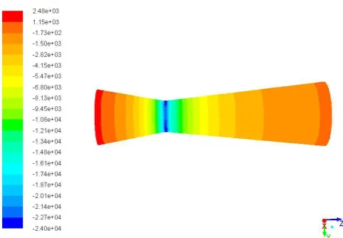
Fig 1. Contours of Pressure for Iteration 1(Pascal)
Fig 2. Velocity Vector for Iteration 1
Fig 3. Contours of Pressure for Iteration 2(Pascal)
[image:3.595.309.573.286.466.2]Fig 4. Velocity Vector for Iteration 2
[image:3.595.41.272.294.545.2]© 2018, IRJET | Impact Factor value: 6.171 | ISO 9001:2008 Certified Journal | Page 4257 Fig 6. Velocity Vector for Iteration 2
Convergent angle of 10.5° & Divergent angle of 6° are selected for restrictor because they gives minimum pressure loss through the restrictor. As per the CDF analysis below convergent angle of 10.5° & Divergent angle of 6° pressure drop increases according to the results of convergent angle of 9° & Divergent angle of 5°.
2. Plenum
Spherical shape type plenum was considered. Performance of engine at higher speeds improves with increase in plenum volume. Volume of plenum is 1.2 liter, which is almost 3 times the engine displacement.
3. Runner
Calculation of Runner Length:
Speed of pressure wave = 1116.44 feet/second
Effective Cam Duration (ECD) = 226°
EVCD = Effective Valve Closed Duration
= 720-(ECD) = (720-226) + 20
= 514°
5000 rev/minute divided by 60 seconds/minute
= 83.33 rev/second
83.33 rev/second X 360°/rev = 30,000°/second
514° / 30,000° per second = 0.0171 seconds.
At 5000 RPM, 514° = 0.0171 seconds
This 0.0171 seconds is the critical time factor. During this 0.0171 seconds that the intake valve is closed, the pressure wave is moving at 1116.44 feet/second and travels 19.12 feet.
At resonant conditions, the pressure wave has to travel 19.12 feet to arrive at the intake valve when it is open. Since the pressure wave spends this time going up the runner AND going back down the runner, the runner length is actually only half of 19.12 feet, or 9.56 feet, which is equal to 114.77 inches.
But, here we can’t use such long runner, so we divide it (by 7) as suitable.
Runner Length = 16.39 inches = 416 mm
According to RAM Theory, intake system was tuned at 5000 RPM, resulting in total runner length of 416mm.
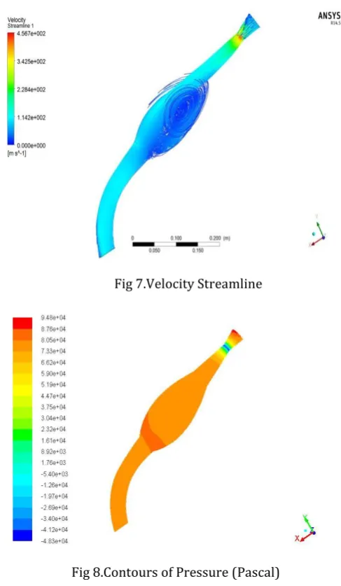
The CFD of whole air intake system is also done at the end in Ansys Fluent by applying appropriate boundary conditions.
[image:4.595.308.552.298.717.2]Fig 7.Velocity Streamline
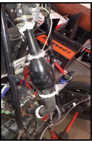
© 2018, IRJET | Impact Factor value: 6.171 | ISO 9001:2008 Certified Journal | Page 4258 Fig 9.Air Intake Assembly
Fig 10. Final assembly of air intake
IV. CONCLUSION
The flow analysis using Computational fluid dynamics (CFD) helps to analyze the flow in the intake manifold. The entire intake system should be optimized to reduce pressure loss and improve engine performance. Convergent angle of 10.5° & Divergent angle of 6° are selected for restrictor because they gives minimum pressure loss through the restrictor.
ACKNOWLEDGMENT
We would like to express my sincere thanks to our friend Aditya Kadam who helped us out in performing the Computational Fluid Dynamics accurately, after a lot of practice and hours put into it. Our sincere thanks to Prof. S. N. Waghmare of Mechanical Department for giving us the opportunity to take up this paper, for his guidance and supervision in all respects of this paper.
REFERENCES
1. Singhal, A., &Parveen, M. (2013). Air Flow Optimization via a Venturi Type Air Restrictor. In Proceedings of the World Congress on Engineering. London.
2. Rahul Puri, Harshal Darade, Yogesh Supekar , Sushant Ulavi, Santosh Kumar Bawage (2016), “Design and Analysis of Intake and Exhaust System of SAE Supra Race Car” International Research Journal of Engineering and Technology (IRJET) Volume: 03 Issue: 06 | June-2016 www.irjet.net © June-2016, IRJET | Impact Factor value: 4.45 | ISO 9001:2008 Certified Journal.
3. Shinde, P. A. (2014). Research and optimization of intake restrictor for FormulaSAE car engine. International Journal of Scientific and Research Publications, 4(4).
4. Logan M. Shelagowski and Thomas A. Mahanak. Formula SAE intake restrictor Design and performance. Saginaw Valley State University.
5. Sachin N Waghmare, Nikhil S Karekar, Pankaj P Karande, Santosh B Pandhare,“Design & Analysis for Intake System of Formula SAE Car” International Research Journal of Engineering and Technology, Management & Applied Science (IRJET) February 2016,Volume 4, Issue 2, ISSN 2349-4476.
6. Shubham Raj, Ashish Kr. Singh, Tuhin Srivastava, Vipul Vibhanshu. “Analysis of Air Intake for Formula SAE Vehicle” Krishna Institute of Engineering and Technology Ghaziabad, UPTU, Vth International Symposium on “Fusion of Science & Technology”, New Delhi, India, January 18-22, 2016.
7. Kaushal Kishor, “Design and Fabrication of Intake and Exhaust Manifold of a Prototype Race Car”, Department Of Mechanical Engineering National Institute Of Technology, Rourkela,Rourkela-769008,Odisha, India, May 2015.
[image:5.595.91.250.346.590.2]