© 2017, IRJET | Impact Factor value: 5.181 | ISO 9001:2008 Certified Journal
| Page 475
Software Defined Network Based Internet on Thing Eco System For
Shopfloor
Avijit Deb Sarkar
11
TATA Consultancy Services & Saltlake Solution Architect
---***---Abstract -
The Present day the manufacturing industriesare looking for solutions to achieve high availability (HA) and secure platform for real-time data transfer process. The cost efficient solution for this HA platform is Cloud Server. The Software Defined Network (SDN) help cloud providers to manage and program their network efficiently in flexible manner. This type of network is agile and easily scalable based on business requirement. In advance manufacturing unit the wireless sensors, actuators and mobile devices are integrated with machines as IoT devices. Due to unstructured data format the security implementation of IoT on SDN architecture is a challenging task. In this article has proposed a secured architecture for IoT devices in an SDN based network to address HA, Security and Real-Time data transfer process.
Key Words: Software Define Network, Internet on Things, Cloud Computing, Manufacturing Execution System.
1. INTRODUCTION
The next technological trends for manufacturing units are IoT, Mobile Computation, Big Data, Social Media Integration. This new computation techniques are leverage the computational features of sensor nodes. In recent days most of the sensors are connected with micro-computers. Those sensor connected micro-computer nodes are capable of transmitting data directly from machines to enterprise databases. These inter-connected devices are transmitting high definition multimedia, text files, audio, video etc. The volume, velocity and verity [1] of data has been generated by the connected devices which requires high speed internet connection with low power and secure computational platform. Low power and efficient encryption methodology is a primary consideration for security while data is being transmitted across the devices. Additionally with the development of latest Internet technology multiple Sensor based devices are interfacing with other connected devices and servers. The IoT devices expose data in insecure manner which leads to various potential threats. An efficient security architecture has to be worked out in this paper for the IoT platforms. In the conventional enterprise network different security tools like Firewall, Intrusion Detection System (IDS) is deployed to increase the reliability of the entire network. The new systems administration would be, the SDN offers wide range of options to secure the system in a more productive and adaptable way [2]. SDN architecture separates the control plane from the data plane in the network. In legacy network as per the built in instructions of
the switches, packets are moved to the same destination along the same path. In SDN packet forwarding rules are managed by the controller. This paper highlights the major security challenges of IoT Devices and propose a secure architecture for the IoT in the SDN platform.
2. SDN ARCHITECTURE
SDN architecture supports wide range of cloud architecture and enables scalable, automated and on-demand Information Technology (IT) Infrastructure platform. SDN architecture defined based on open source software and commodity hardware. In traditional network the control and data plane elements are packaged together. In OpenFlow[3] standard created in 2008, recognized as first SDN architecture that separated the control plane and data plane elements and they use OpenFlow protocol for communication. The OpenFlow protocol is defined by Open Network Foundation (ONF). However, there are other standards and open-source organizations with SDN resources, so OpenFlow is not the only protocol that makes up SDN. The purpose of the SDN is to improve user experience with minimum cost.
2.1 SDN Stacks
SDN make the network agile and flexible by separated the control plane and data plane of the networking stack. The working principle of SDN is to separation of responsibility. The SDN Stack broadly divided into three different tires and two types of interfaces:
a. Application
Encompasses solutions that focus on the expansion of network services. These layer contain mainly software applications that communicate with the controller.
b. Control Plane
Includes a logically-centralized SDN controller, which maintains a global view of the network. It also takes requests through clearly defined APIs from application layer and performs consolidated management and monitoring of network devices via standard protocols.
c. Data Plane
© 2017, IRJET | Impact Factor value: 5.181 | ISO 9001:2008 Certified Journal
| Page 476
configurable and high performance hardware and software,which is compliant with industry standards.
d. Northbound Interface and Southbound Interface
A northbound interfaces are used by a particular network component to communicate with a higher-level component, enable alarm notification, performance report, configuration, security log, network inventory details etc. Conversely, a southbound interface allows a particular network component to communicate and manage with a lower-level component.
Fig 1: SDN Architecture [4]
2.2
Pros and Cons of SDN
a. Advantages
The benefits of SDN is centralized network provisioning capability. By abstracting the control plane and data plane SDN can achieve more agility on provisioning virtual and physical devices from central location. SDN controller provides centralized security control as a result the security policies are consistent across the enterprise. SDN controller can run on low cost commodity hardware.
The IoT devices are the key driver for SDN. Given the complexity and scale, it is really difficult to manage network manually. SDN provides the cost-effective solutions to manage the sensor network and the data on it. SDN implementation help to optimize the bandwidth utilization and maximize the efficiency of the applications and analytics that use its data.
b. Disadvantages
In SDN the network device configuration is done using web interface hosted in controller. The location of the controller can be on premises or in physically distributed location. One area of concern is the connection between the controller and the communicated network devices. So all configuration related communications are based on HTTP or HTTPS. If that fails or becomes compromised, the entire network not only lose the connection to the controller also goes down. SDN also introduce new potential security called Distributed Denial of Services (DDoSing).
2.3 Security Consideration of SDN a. Single SDN Controller Approach
In single controller SDN environment the Denial of Service (DoS) attack is a major threat. In this approach if the SDN controller compromised by any attacker then they can take full control over the network. Hence a single controller environment has always a major risk for entire network. Multiple controller approach is the solution for low risk and enhance reliability to the network system. In multi controller environment for any failure of one controller, another physically separated SDN controller can take over the control to prevent the entire network failures.
b. Multiple SDN Controller Approach
It is observed that multiple controllers can
increase availability of the system. The default feature of high availability (HA) is to make available either of the two system if there is any failure happen. In practice it has observed that multi controller SDN platform effects network performance. In multi controller environment each controller has primary responsibility to manage a particular network segment, so controller has to compute the route to collaborate with each other and exchange information which creates extra computation overhead.
3. IoT Implementation in SDN
[image:2.595.45.295.241.471.2]© 2017, IRJET | Impact Factor value: 5.181 | ISO 9001:2008 Certified Journal
| Page 477
Fig 2: Connectivity of IoT in SDN Platforma. IoT Sensor Node
It is responsible to sense, analyze and collect the information from the machines as production feedback for business users also downloads require data to machines based on response generated from IoT controller. All the IoT Sensor Node needs to be registered in local IoT controller with the details like Device Id, IP Address, Public Key, and Communication Protocol.
b. IoT Controller Node
It takes the necessary decisions based on the data provided to it by the IoT Sensor Nodes. These data are route to the Cloud Servers using network devices via the SDN controller. IoT controller receive the data from sensor node and process the same based on “IsProcessRequire” flag value. After processing controller responsibility to decide the destination route of the data, if the processed data is require for other connected devices then controller send the processed data to the intended devices else it transfer data to database hosted in Cloud Server. The entire communication is managed by the SDN controller.
c. SDN Capable Heterogeneous Network
It has the responsibility to establish the communication path between connected sensors and cloud server and surrounding systems like Reporting System, SCM, and ERP etc. Some of the surrounded systems responsible to display production status in real-time based production feedback received from IoT devices. In MES environment data velocity, verity, volume is always high because the sensor node continuously sends data to enterprise system. The SDN architecture is responsible to manage this high traffic heterogeneous network environment. The SDN controller also monitor the request and response data packets. It has responsibility to manage the security protocols for IoT
network from different vulnerable attacks. In SDN platform OpenFlow switches [4] contains the security policies for the connected segment.
4. Proposed Security Framework
IoT network be made up of different resource constrained sensor devices Android Mobile Phones, SoC board such as Raspberry pi, Arduino, ATMeg32 based controller etc. Each IoT devices are connected to local IoT Controller and it is connected to cloud server via SDN. The entire IoT network is segmented into multiple heterogeneous network. The local IoT controller has enough computation capability resources.
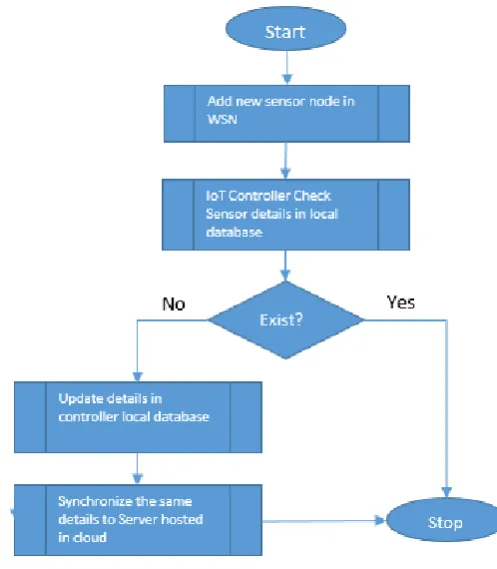
The sensor node encrypt the data using its own private key and send that to IoT Controller. The IoT controller is responsible to process the data and forward to central database to store and process further for enterprise use. Whenever a new IoT based sensor node introduced then it updates the details to controller similarly controller updates that information to central server. The flow chart is explained in Fig 3.
Fig 3: Flow Chart
5. DATA Structure for IoT Security Framework
[image:3.595.50.285.83.280.2] [image:3.595.315.564.359.644.2]© 2017, IRJET | Impact Factor value: 5.181 | ISO 9001:2008 Certified Journal
| Page 478
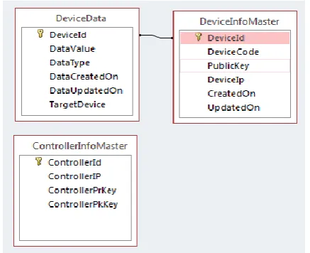
5.1 Data Structure for Controller Node [image:4.595.330.549.89.267.2]All connected IoT sensor node information will be stored in “DeviceInforMaster” table. When a new node introduced in the network then sensor node call REST service hosted in controller and update its own device information. The central server always scan this table for new information and based on that its updates itself. IoT controller always executes a job in regular interval to read sensor data from device and save that into “DeviceData” table. Also if that data contains target machine details then controller decrypt that data and encrypt using controller private key and send to target device for further processing.
Fig 4: DeviceInfoMaster Entity Details
Fig 5: DeviceData Entity Details
Fig 6: ControllerInfoMaster Entity Details
Fig 7: Data Structure of Key Management System in IoT Controller
5.2 Data Structure for Sensor Node
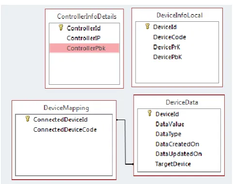
Sensor node data structure consist of 4 tables one is for controller information and remaining three for device internal use. The controller table (“ControllerInfoDetails”) is populated by sensor based on the exposed controller information. REST protocol has used to expose the data. Sensor node save the device id, device code, public key and private key into local table “DeviceInfoLocal”. The operator can map other device using REST based web service. The mapping information kept in “DeviceMapping” table. All sensor information saved into local table called “DeviceData” and then send to controller for further processing. This table automatically purge after 72 hours, however this schedule is also configurable.
Fig 8: DeviceData Entity Details
[image:4.595.48.297.254.353.2]© 2017, IRJET | Impact Factor value: 5.181 | ISO 9001:2008 Certified Journal
| Page 479
Fig 10: DeviceInfoLocal Entity DescriptionFig 11: Data Structure of Key Management System in IoT Device
5.3 Key Management Logic & Application
The relationship among the Cloud Server, IoT Controller and Sensor Node has been mentioned in section VII. This architecture is platform and technology independent. The Sensor Nodes are responsible to generate Private Key, Public Key and Device Code for the first time whenever it connected to the network, similarly the IoT Controller is responsible to generate Public Key for Data/Application Server and Sensor Node.
The sensor node expose key and device code using REST based web service. The IoT controller node periodically check the REST web service and insert the device code and public key to “DeviceInfoMaster” table. Application administrator can set change the frequency by which the key will be updated by the sensor node. Using this functionality application administrator can modify only public key or both public and private key based on security needs. MAC Address has considered as unique DeviceId. The entire communication has done through REST based web service, so that all types of device can consume that data.
5.4 Data Transfer Mechanism
This paper has proposed push mechanism for data transfer activity from sensor node to IoT controller node and pull
mechanism from IoT controller node to central server. The relationship among the cloud server, IoT controller and sensor node has been mentioned in section VII. The sensor nodes always encrypts data using its own private key and then controller public key. Once controller received the data form sensor node it checks the target device filed and if that field is blank then it decrypt the data using its private key and then upload the encrypted data to central server hosted in cloud. If the target device field non empty then it decrypt the data using its own private key and then source sensor public key and then perform required operation and finally before send that data to destination sensor node again it encrypt using its own private key and destination sensor public key and then send. This implementation has been done in Steel Manufacturing Industry for Material Transfer Module, Scrap Weighing Module and Production Feedback Module. The architecture in generic enough to implement in other manufacturing industries.
Fig12: Architectural Diagram
In above Architectural Diagram (Fig 12) different units is running in different network segment and each segments are connecting among themselves via SDN. Each segment has its own IoT controller which is connected to one or more IoT sensor node. This design is platform and technology independent.
6. Benefits and limitations
6.1 Benefits
a. This design is platform independent, so it can
implement with existing technology and no need to change the technology platform.
© 2017, IRJET | Impact Factor value: 5.181 | ISO 9001:2008 Certified Journal
| Page 480
c. All communications among the systems are encrypted
based on asymmetric key encryption.
d. The push mechanism has been used to update the
sensor data in sensor node and IoT Controller Node. This push mechanism is optimum solutions for resource constrain systems.
e. Pull mechanism has been used in application server to
fetch data from IoT Controller node for further processing at enterprise level.
6.2 Limitations
a. The proposed architecture may not match with old
legacy system because in practical scenario it is identified that the few old systems are incompatible to communicate with latest system.
b. Old PLC and Machine controllers were using the Serial
port for upload and download machine data whereas latest PLCs and OPC systems are using TCP/IP protocol for the communication. So a separate data extraction and transfer code is required to integrate this architecture for old legacy system. Sometimes it is noticed that this extra layer increases the complicity of the system which directly affect system performance.
CONCLUSION
This paper I have proposed an architecture for MES platform for Steel Industry. This proposed architecture had been implemented in client place and it is working as expected without any glitch. Need to explore the scope and feasibility to implement this architecture for other type of manufacturing industries like car manufacturing, packet manufacturing etc.
The major implementation challenges was to implement this system to upstream furnace area because that is most hazardous environment. This implementation help client to get return of investment within two months by reducing human intervention at scrap weighing area.
ACKNOWLEDGEMENT
There have been many contributors for this to take shape and I am thankful to each of them. I specifically would like to thank my supervisors Mr. Sujan Das and Mr. Basudev Acharya. The work has been partially implemented for one of our customer’s manufacturing unit.
REFERENCES
[1] A Review Paper on Big Data and Hadoop :
http://www.ijsrp.org/research-paper-1014/ijsrp-p34125.pdf
[2] Sood, Manu. ”Software defined networkArchitectures.”
Parallel, Distributed and Grid Computing (PDGC), 2014 International Conference on.IEEE, 2014.
[3] Openflow :
https://www.opennetworking.org/sdn-resources/openflow
[4] SDN Architecture Image
![Fig 1: SDN Architecture [4]](https://thumb-us.123doks.com/thumbv2/123dok_us/8152913.803166/2.595.45.295.241.471/fig-sdn-architecture.webp)