© 2017, IRJET | Impact Factor value: 5.181 | ISO 9001:2008 Certified Journal
| Page 303
Automatic Floor Cleaner
Manya Jain
1, Pankaj Singh Rawat
2, Assist. Prof. Jyoti Morbale
312
B.Tech in Electronics Engg. BVDUCOE, Pune, Maharashtra, India
3
Assist. Professor in Electronics Engg. BVDUCOE, Pune, Maharashtra, India
---***---Abstract
–
The research paper details the development of Automatic Floor Cleaner. The project is used for domestic and industrial purpose to clean the surface automatically. When it is turned ON, it sucks in the dust by moving all around the surface (floor or any other area) as it passes over it. The controller is used to drive the motors and the suction unit also a couple of sensors are used to avoid the obstacles. This can be useful in improving the lifestyle of mankind.Key Words: Microcontroller, Motor Driver, Ultrasonic Sensor, Suction Unit, Vacuum Unit.
1.INTRODUCTION
In the modern era, the Automatic Floor Cleaner is required. Thus, the cleaner is designed in such a way that it is capable of cleaning the area reducing the human effort just by starting the cleaning unit. In the paper, main focus is to build and program it in such a way, that it can move around freely and clean a specific area by the vacuuming process.
Brushes are attached at its side in order to collect the dust while moving. It uses Ultrasonic sensors to detect the obstacles and hence change its direction while moving and also preventing the cleaner to fall from height.
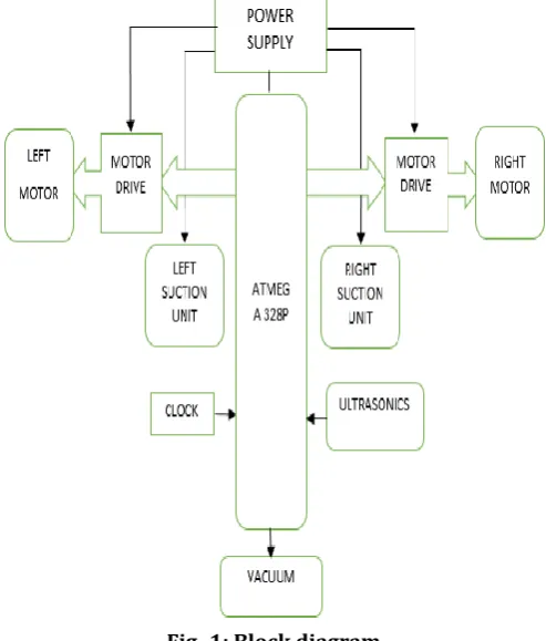
1.1 SYSTEM ARCHITECTURE
Fig-1: shown below is the block diagram of Automatic Floor Cleaner. [image:1.595.310.557.215.505.2]
Microcontroller (ATmega 328p) is used which is provided with clock signal (quartz crystal operating at 16 MHz frequency). DC motors attached to motor drivers to provide high current and most importantly it is installed with a sensors and suction unit to perform vacuum operation effectively. For Power Supply two separate batteries are used. One is used to turn on the cleaning unit and other is used to provide power to the suction unit.
Fig -1: Block diagram
A. Hardware used:
a) ATmega 328p/ Arduino b) Ultrasonic sensor (SC-H04) c) Motor driver (L293D) d) Suction unit (Vacuum)
ATmega328/ Arduino:
© 2017, IRJET | Impact Factor value: 5.181 | ISO 9001:2008 Certified Journal
| Page 304
[image:2.595.40.278.209.371.2]modes. The device operates between1.8-5.5volts. The device achieves through put approaching 1 MIPS per MHz Serial data to the MCU is clocked on the rising edge and data from the MCU is clocked on the falling edge. Power is applied to VCC while RESET and SCK are set to zero. ATmega328 is commonly used in many projects and autonomous systems where a simple, powered, low-cost microcontroller is needed.
Fig -2: Arduino pin description
The Arduino Uno is a microcontroller board based on the ATmega328. It has 14 digital input/output pins (of which 6 can be used as PWM outputs), 6 analog inputs, a 16 MHz crystal oscillator, a USB connection, a power jack, an ICSP header, and a reset button. It contains everything needed to support the microcontroller; simply connect it to a computer with a USB cable or power it with an AC-to-DC adapter or battery to get started. The Uno differs from all preceding boards in that it does not use the FTDI USB-to-serial driver chip. Instead, it features the Atmega8U2 programmed as a USB-to-serial converter.
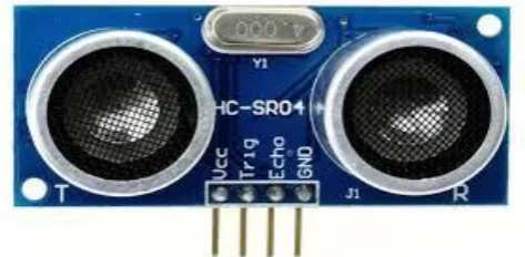
Ultrasonic sensor (SC-H04):
[image:2.595.312.550.218.369.2]Ultrasonic ranging module HC - SR04 provides 2cm - 400cm non-contact measurement function, the ranging accuracy can reach to 3mm. The modules includes ultrasonic transmitters, receiver and control circuit.
Fig -3: Ultrasonic Module
The basic principle of work:
(1) Using IO trigger for at least 10us high level signal. (2) The Module automatically sends eight 40 kHz and detect whether there is a pulse signal back.
(3) IF the signal back, through high level , time of high output IO duration is the time from sending ultrasonic to returning. Test distance = (high level time) * (velocity of sound (340M/S) / 2.
[image:2.595.40.277.628.744.2]Motor driver (L293D):
Fig -4: Motor driver shield
a) Four H-Bridges: Two L293D Motor driver chips b) L293D is rated at 0.65A per bridge (1.20A peak)
with thermal shutdown protection, Motor Voltages from 4.5VDC to 16VDC. (up to 36V if C6 and C7 are upgraded)
c) Up to 4 bi-directional DC motors with individual 8-bit speed selection (256 speeds)
d) Up to 2 stepper motors (unipolar or bipolar) e) Pull down resistors keep motors disabled during
power-up
f) Separate Logic and Motor power connections g) Terminal block connectors for motors and power h) 2 connections for 5V 'hobby' servos
Suction unit (vacuum):
© 2017, IRJET | Impact Factor value: 5.181 | ISO 9001:2008 Certified Journal
| Page 305
B. Software Description
[image:3.595.305.536.112.402.2]To program the Arduino the Arduino IDE is used which is free software that enables programming in the language that the Arduino understands. In the case of the Arduino, the language is based on C/C++ and can even be extended through C++ libraries. The IDE enables writing a computer program which is a set of step-by-step instructions that is then uploaded to the Arduino. Arduino will then carryout those instructions and interact with whatever it has been connected to it. In the Arduino world, programs are known as “sketches”.
Table -1: Software and Hardware Specifications
SR.
No.
Requirement Specification
1. Battery Life 2 hours
2. Vacuum At least 90%
3. Store dust Maximum 64 cm3
storage
4. Weight Max 5 kg
5. Cleaning Time Approximately 25 Minutes
6. Software Arduino ide
7. Communication
Protocol UART
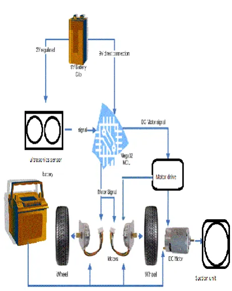
[image:3.595.28.278.281.727.2]1.2 WORKING
Fig -5: Working Diagram
The automatic floor cleaner is intelligently programmed to clean a specific area through a vacuum cleaning assembly. The cleaner is cost effective, convenient, environment friendly that saves the valuable time of any person.
The vacuum cleaner is made on a circular piece of board that has wheel beneath it and brushes attached at its side in order to collect the dirt as it passes over the surface. DC motor is used to change direction of wheels which is connected to the platform. If the enough current is produced then DC motors can be operated directly otherwise a motor driver is required so as to provide it a high current i.e. upto 0.7 to 1.2 ampere. Driver Used is named as L293D with H-Bridge Configuration. The cleaner is handy and can spin anywhere in any direction.
© 2017, IRJET | Impact Factor value: 5.181 | ISO 9001:2008 Certified Journal
| Page 306
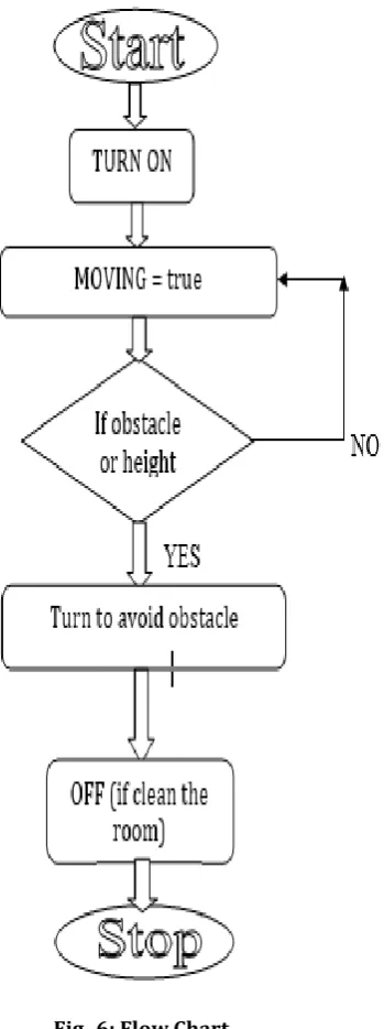
[image:4.595.97.272.183.651.2]A self-build suction unit is attached to the brushless DC motor rotating at a very high speed. It suck in the dirt as soon as it is turned on. It can be detached and the dirt can be removed from it.
Fig -6: Flow Chart
2. FUTURE SCOPE
In today’s era, 95 percent of the cost of cleaning a floor is labor. Naturally, the high cost of this simple task has inspired alternative solutions and that is Automatic Floor Cleaner.
From industries to homes automatic floor cleaner is used and is becoming a very important part of life as it saves time, money and reduces human efforts to a great extent. Its approximate cost is 5000 INR. It is the future of cleaning in our fast moving life. It is no surprise that they would probably be more reliable than the manual sweeping.
3. CONCLUSIONS
This research facilitates efficient floor cleaning. Since in project the floor cleaner is incorporated with different devices like DC motor(s), ultrasonic sensors etc., so it will be easy to handle it also saves time and will work automatically for cleaning purpose at homes and offices.
With simple algorithm and program, the cleaner will be able to cover large floor areas as well as find its way into and out of small corners. As the cleaner traverses the room, the sweeper installed in it will manage to pick up a significant amount of dirt. Manual Sweeping might not be that effective as it will not be picking up everything in as it is not in sight but using the automatic floor cleaner it can be done easily.
ACKNOWLEDGEMENT
We would like to express our deepest gratitude to our Head of Department Dr. A. A Shinde for providing us the opportunity to build this project. We heartily thank our project guide Mrs. Jyoti Morbale for her valuable guidance and constant support throughout the project.
REFERENCES
[1] Uman Khalid , Muhammad Faizan Baloch , Haseeb Haider , Muhammad Usman Sardar , Muhammad Faisal Khan, Abdul Basit Zia1 and Tahseen Amin Khan Qasuria Faculty of Electronic Engineering, Ghulam Ishaq Khan “Smart Floor Cleaning Robot (CLEAR)” Institute of Engineering Sciences and Technology, Pakistan Hamdard Institute of Engineering & Technology, Hamdard University, Karachi, Pakistan 2015.
© 2017, IRJET | Impact Factor value: 5.181 | ISO 9001:2008 Certified Journal
| Page 307
[3] Jens-Steffen Gutmann, Kristen Culp, Mario E. Munich and Paolo Pirjanian. The Social Impact of a Systematic Floor Cleaner. In IEEE international workshop on advance robotics and its social impacts, Technische University munchen, Germany May 21-23, 2012.
[4] Evolution Robotics Inc. Introducing Mint-the
evolution of floor care,
www.mintcleaner.com,2011.
[5] J Frolizzi C.Disalvo. Service robots in the domestic environment: A study of Roomba vacuum in the home”. In int. conference on human robot interaction HRI, PAGE 258-265 March 2006.
[6] G Tuangzhi Dai and Tiequn Chen.Design on measurement and control system of cleaning robot based on sensor array detetion.In IEEE International conference on control automation Guangzhou, CHINA-MAY 30 to June 1, 2007.
[7] H.Asada and J.-J E. Slotin, robot analysis and control, a wiley-interscience publication, 1986, pp. 29-49.
BIOGRAPHIES
I, Manya Jain, am a final year student of Electronics Dept. in Bharati Vidyapeeth Deemed University College of Engineering, Pune.
I, Pankaj Singh Rawat, am a final year student of Electronics Dept. in Bharati Vidyapeeth Deemed University College of Engineering, Pune.