© 2018, IRJET | Impact Factor value: 6.171 | ISO 9001:2008 Certified Journal | Page 4020
Traffic Control Management with help of State of Control Algorithm
using Ultrasonic Sensors & GSM Technology
Hamara Chaudhuri
1, Nishanth P Raikar
21,2
Student VIII Semester, Dept of E&C, The National Institute of Engineering, Mysuru
---***---Abstract - We have proposed the optimization of Traffic
Light Controller using ultrasonic sensor and microcontroller and those reporting to reach destination at last-mile connectivity to Traffic Light authority using GSM.
The Paper is aimed at designing a density based dynamic traffic signal system where the timing of signal will change automatically on sensing the traffic density at any junction. Traffic congestion is a severe problem in most cities across the world and therefore it is time to shift more manual mode or fixed timer mode to an automated system with decision making capabilities. Present day traffic signaling system is fixed time based which may render inefficient if one lane is operational than the others. To optimize this problem we have made a framework for an intelligent traffic control system. Sometimes higher traffic density at one side of the junction demands longer green time as compared to standard allotted time.
We, therefore propose here a mechanism in which the time period of green light and red light is assigned on the basis of the density of the traffic present at that time. This is achieved by using ultrasonic sensors which are present on Top of the road.
Sometime,in particular junction of the road faces long hours of Red Traffic Light.In case of any vehicle in emergency situation or in last-mile connectivity issues like VVIPs,a SMS is send to Traffic Control Authority,who in-turn enables microcontroller to change traffic light green for particular time on priority basis.
Key Words: Traffic Signals, Ultrasonic Sensors, Arduino Microcontroller, GSM Module
1.
INTRODUCTION
In today’s high speed life,traffic congestion becomes a serious issue in our day to day activities. It brings down the productivity of individual and thereby the society as lots of work hour is wasted in the signals. High volume of vehicles, the inadequate infrastructure and the irrational distribution of the signaling system are main reasons for this chaotic congestions. It indirectly also adds to the increase in pollution level as engines remain on in most cases, a huge volume of natural resources in forms of petrol and diesel is consumed without any fruitful outcome. Therefore, in order to get rid of these problems or at-least reduce them to significant level, newer schemes need to be implemented by bringing in sensor based automation technique in this field of traffic signaling system.
2.
PRESENT SCENARIO
In the present scenario the vehicle problem is increasing and Traffic congestion is a severe problem in many modern cities all over the world.
Traffic Control is achieved by the use of a system of hand signs by traffic police personnel, traffic signals, and markings. To overcome the problem, we have come up with an exclusive idea for a dynamic and automatic traffic light control expert system combined with a simulation mode. Traffic research has the goal to optimize traffic flow ,as the roads have become overloaded with increasing number of vehicles and resources are limited.
However, still there are some limitations in existing traffic control which are not environmental and economical. There are several models which give solutions for traffic simulation.
In our research we have focused on optimization of traffic light controller in a city using wireless sensor and automate decision. Traffic light optimization is a big problem. Even for single junction there is no optimal solution. The problem becomes even more complex with multiple junctions, as the state of one light is responsible for the flow of traffic of that road only.
Under current circumstances, traffic lights are set on in the different directions with fixed time delay, following a particular cycle while switching from one signal to other creating unwanted and wasteful congestion on one lane while the other lanes remain vacant.
The system we propose identify the density of traffic on individual lanes and thereby regulate the timing of the signals’ timing. Ultrasonic trans-receivers count the obstructions and provide an idea about the traffic density on a particular lane and feed this response to a controller unit which will make the necessary decisions as and when required.
In this paper, we propose three approaches :
In the first approach - to take data/input/ from ultrasonic receivers.
© 2018, IRJET | Impact Factor value: 6.171 | ISO 9001:2008 Certified Journal | Page 4021 In the third approach whenever any any vehicle in
emergency situation or in last-mile connectivity issues like VVIPs,it will send a message to the authority of that traffic light and traffic police,to turn on that particular traffic light in the city.
3.
SYSTEM MODELING
In this section, we focus on the use of ULTRASONIC SENSOR and wireless N/W in traffic control. A lot of scope can be gained in this idea, and intelligent traffic control attracted several governments and commercial companies. Our main aim is to provide more secure roads with less travel time. Such improvements will lead to health benefits, economy, and the environment.
Basically in our proposed system on one side of a single lane road, the ultrasonic sound transmitters are placed which produces ultrasonic waves and these ultrasonic transmitters are placed at a distance ( approx 10- 15 meter gap). On the opposite side of same road the ultrasonic receivers are placed at the same gap as that of ultrasonic transmitters which receives the waves .
This system will keep track of the road and whenever the series of ultrasonic receivers does not receive the sound than it indicates the microcontroller about the density of traffic jam.
In our proposed system ultrasonic sensors are placed on the road. When their transmittance is disturbed by the moving vehicles they convey that message to the microcontroller for generating results. Which will be described below in upcoming topics.
Unlike all others system for measuring traffic density where sensors are placed on the road here we are installing ultrasonic sensors above the road on the foot-path and railings in between the roads. The advantage of this technique is that the ultrasound will not pass below the vehicles and conveying a wrong message to controller is be avoided.
After that this system will also work when there is excess of water flowing on road during rain or also above the sensors , because ultrasound can also travel in water or we say travels faster in water according to science.
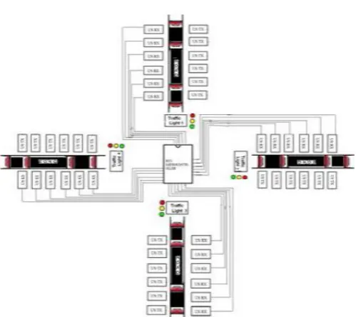
[image:2.595.312.562.71.293.2] The chances of failing this technique is very less because this system overcomes all the possibilities that affects a signalling system.
Fig.- 1 : The Model of the Traffic Light
4.
BLOCK DIAGRAM
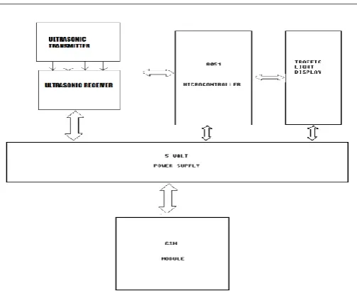
In this paper we are mainly interested in the optimization of traffic flow, thus effectively minimizing the Average travelling time of cars. A common tool for analyzing traffic is the traffic simulator. In this section we will first describe block diagram as shown in the figure no. 2 to model traffic controllers. We will then describe how this models can be used to obtain real-time traffic information or predict traffic conditions. After that in this paper we describe how information is communicated as a means of controlling traffic, and what is the effect of the communicated data on traffic conditions will be.
4.1 Power Supply :
As per the power requirement of the hardware of the intelligent traffic light control and monitoring system, supply of +5V w.r.t GND is developed as shown in Figure no. 3. The complete circuitry is operated with TTL logic, '1' or '0' i.e. 1.7 volt for '0' and 5 volt for '1'.
4.2 Ultrasonic Sensor :
In our proposed system ultrasonic sensor is going to play a very vital role. This sensor will help us to recognize the traffic jam density and work accordingly. This sensor is going to initiate the whole working of the system.
© 2018, IRJET | Impact Factor value: 6.171 | ISO 9001:2008 Certified Journal | Page 4022 The use of ultrasonic sensors in data delivery in real time
can save the usage of bandwidth servers in the reception and delivery of data, so that will make the use of data networks less and more quickly in receiving data.
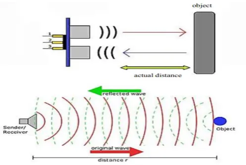
[image:3.595.314.547.89.224.2]Ultrasonic waves generally reside at frequencies exceeding 20 kHz.An ultrasonic transmitter transmits the ultrasonic waves of frequency above 20khz in the air towards the ultrasonic receiver.Now the ultrasonic receiver will receive the ultrasonic waves transmitted by the transmitter. As we are using digital ultrasonic receiver ( US 18) so the output pulse would be in the form of either '0' or '1'. If we are receiving a pulse then it will result in "1" else "0". The resulting output pulse will be sent to the microcontroller.
Fig.- 2 : Ultrasonic Sensor
4.3. Microcontroller :
A microcontroller is an economical computer-on-a-chip built for dealing with several specific tasks, such as receiving information through PORTs or remote controlled devices and processing it further to give appropriate result for which it is programmed.
Arduino Mega is an ATmega328-based microcontroller consisting of 54 input and digital output pins, of which 15 pins are PWM output, 16-pin analog input, 16 MHz resonators, USB connections, power supplies, ICSP headers and reset buttons. Arduino Mega can use the battery or directly from the USB port.
[image:3.595.38.287.253.420.2]The Arduino software includes a serial monitor that allows simple textual data to be sent to and from the Arduino board. LED RX and TX on board will blink when data is sent via USB-to-serial chip and USB connection to computer (but not for serial communication on pins 0 and 1). A Software Serial library allows serial communication on one of Arduino Mega’s digital pins.
Fig.- 3 : Arduino Mega 2560 Microcontroller
This system is an intelligent traffic light control and monitoring system which shows the interfacing of some peripherals and ICs with the microcontroller.
As the power is switched on the microcontroller will come in to action it will activate all the sensors for 5 sec and then turn them off. Sensors which are available on all the four roads will supervise the traffic density on the individual basis. And the pulses received by the sensors will be sent to microcontroller and the comparator is going to compare the data of individual four road given by the sensor and the road with the maximum value of traffic will be given first priority as a green light for the defined time for particular level of jam will be set first for that particular road.
We assume the first road as reference road and after that traffic light will shift in clockwise manner. After that when time period for green light on first road remains only 5 sec then at that peak of time, microcontroller activates the ultrasonic sensors on the road which comes first in clockwise direction to the reference road and measures the traffic density of that road and microcontroller takes the decision for setting the timing interval.
After that the same process will be repeated for next road and the cycle will be continued.
4.4 Traffic Light Display :
© 2018, IRJET | Impact Factor value: 6.171 | ISO 9001:2008 Certified Journal | Page 4023 Fig.- 4 : Block Diagram of The Model
4.5 GSM Module :
GSM is GLOBAL SYSTEM FOR MOBILE COMMUNICATION. through this module we can send and receive calls and messages and the traffic light can be monitored through mobile phones of authorized person.We are using it as, when any problem arises in the commuter’s Last-mile connectivity to reach destination in fast possible time then this module will send a message to the authority person describing the Traffic Junction Unique number in the city with the problem. This will help for better results in improving the conditions of fast-paced people like VVIPs,Emergency Health Ambulance ,etc.
Fig.- 5 : The GSM Module of SIM 800A
5. OPERATIONAL MODEL
[image:4.595.306.554.69.268.2]The model works on the principle of changing delay of Traffic signals based on the number of cars passing through an assigned section of the road. There are four sensors placed at four sides of a four way road which counts the number of cars passing by the area covered by the sensors.
Fig.- 6 : The Model of the Traffic Light
Here we are using Ultrasonic sensors replacing system to design an intelligent traffic control system. Ultrasonic sensor contains transceiver in itself. These will be mounted on same sides of the road at a particular distance.
As the vehicle passes through these Ultrasonic sensors, the sensor will detect the vehicle & will send the information to the microcontroller. The microcontroller will count the number of vehicles, and pro glowing time to LED according to the density of vehicles.
If the density is higher, LED will glow for higher time than average or vice versa. The traffic lights are initially running at a fixed delay of 5 seconds, which in turn produces a delay of 20 seconds in the entire process. This entire embedded system is placed at that junction. Microcontroller is interfaced with LEDs and Ultrasonic sensors .The total no of Ultrasonic sensors required are 4 and LED’s 12.
Therefore these are connected to any two ports of microcontroller. Ultrasonic transmitter and receiver pairs, which work as proximity sensor is used. The output voltage according to distance from an object comparator with a reference set. The reference is set by a variable resistance according to required range of sensing.
When the sensor finds any object, comparator low else it gives + 5 V (HIGH). The controller program counts this change of events from LOW to HIGH indicating passing of a vehicle. The objective of the ultrasonic sensor is to detect obstacles and how much distance is it far from incoming vehicles.
Three sets of LEDs viz Green, Yellow and Red are used to indicate the GO state, Ready to Go state and WAIT state.The LEDs G (green), Y (yellow) and R (red) glow following sequence :
[image:4.595.36.278.463.623.2]© 2018, IRJET | Impact Factor value: 6.171 | ISO 9001:2008 Certified Journal | Page 4024 • G3-Y4-R1-R2
• G4-Y1-R2-R3.
Therefore G1 and Y2 are connected to same ports similarly G2-Y3, G3-Y4, G4-Y1. The Red LEDs are connected to separate ports and glows according to the logic given in the Program.
6. CODE SECTION
6.1 Counting mechanism :
digitalWrite(trigPin1,LOW);
delayMicroseconds(2);
digitalWrite(trigPin1,HIGH);
delayMicroseconds(10);
digitalWrite(trigPin1,LOW); duration=pulseIn(echoPin1,HIGH);
distance=duration*0.034/2;
if(distance<=10){
Carcount1++;}
In the above code section,if ultrasonic sensor detects obstacle less than 10cms,it will count number of cars passed through it.Similarly four counters are used for for sensors for counting cars at four directions.
6.2 Delay mechanism of the LEDs :
The delay of LEDs depend on the value of the Counter of each sensor. The function delay() cannot be used as it stops the program till delay is executed and due to this the counters value will not increase for that period of time.To avoid this problem Millis() function is used. Millis function counts milliseconds passed after the program has started.
unsigned long currentMillis = millis();
if (currentMillis - previousMillis>= interval) {
Serial.print("time :");
Serial.println(previousMillis);
previousMillis = currentMillis;
In the above code section currentMillis stores the milliseconds passed. previousMillis stores the time in milliseconds, the last time the same code was executed, initially its zero. Interval is the delay we want, so if the difference between the last time and the current time is more than the interval then only the code will be executed. Therefore the LED states doesn’t change until the time passed is more than the given interval.
6.3 Code for glowing LEDs sequentially and according to the counter value of corresponding sections :
if (currentMillis - previousMillis>= interval) { Serial.print("time :");
Serial.println(previousMillis); previousMillis = currentMillis;
if(digitalRead(G1)==HIGH) {
digitalWrite(G2, HIGH); digitalWrite(G3, LOW);
digitalWrite(G4, LOW); digitalWrite(G1,LOW);
digitalWrite(Y3, HIGH);digitalWrite(Y1, LOW); digitalWrite(Y2, LOW);digitalWrite(Y4, LOW);
digitalWrite(R4,HIGH); digitalWrite(R1,HIGH);
digitalWrite(R2,LOW); digitalWrite(R3,LOW); Serial.print("number of car passed in 2: ");
Serial.println(CarCounter2); interval= 1000*CarCounter2+1000;
CarCounter2=0; }
else if(digitalRead(G2)==HIGH) }
Initially green LED 1 and red LED 3 & 4 are set HIGH, so as the condition if(digitalRead(G1)==HIGH) gets satisfied , it turns the next LED high other LEDs including itself, and G2 LED stays on till time passed is greater than interval. This interval is set according to car counted in each cycle.
interval= 1000*CarCounter2+1000
This is 1000 millisecond or 1 sec for each car passing through the sensor and even if no car passes through the sensor the signal will be ON for atleast 1 second. CarCounter is again set to zero, so that fresh count is done till the next round. Similarly after this interval is over if(digitalRead(G2)==HIGH) will be satisfied as G2 LED is ON now and similarly G3 LED will be made ON and others OFF till next interval, and this will go on.
6.4 FUNCTIONING OF GSM
GSM.begin(9600);
GSM.println("AT");
delay(100);
GSM.println("AT+CMGF=1");
delay(100);
© 2018, IRJET | Impact Factor value: 6.171 | ISO 9001:2008 Certified Journal | Page 4025 The above code section gives setting baud rate of GSM
Module.AT Command gives synchronisation of Arduino and GSM Module.AT+CMGF=1 sets SMS message format to text mode.AT+CNMI gives new messaage indication settings
if(GSM.available()>0){
while(GSM.available()>0){
in_char=GSM.read();
in_string=in_string+in_char;
}Serial.println(in_string);
get_number(); }
It checks whether data is available in the software serial port.Hence it then stores the data in character variable and appends the character in the string.
status1=in_string.indexOf("J1");
if(status1!=-1){
Serial.println("J1 ON");
send_msg("J1 ON");
ledState=HIGH;ledState2=LOW;ledState3=LOW; ledState4=LOW;ledState5=LOW;ledState6=LOW; ledState7=LOW;ledState8=LOW;
cond1(1000);
yellow1(60000);
Serial.println("Timeout!J1 OFF");
send_msg("Timeout!J1 OFF");
status1=-1;
goto X;}
It checks whether Junction “J1 ON” is present in the string.If yes, it sends back SMS that Traffic Light is ON.After Particular time,it will again send SMS that Traffic Light will change as soon as possible.
7. ADVANTAGES
In our concept time interval is changing according to the traffic density on each street and we can say this system as real time operating system (RTOS).
By using this algorithm we finds that this system consumes very much less power because all the ultrasonic sensors of all four streets are not active all the time, they are active only for 5 sec during the transition of green light from one street to another.
8. CHALLENGES AND FUTURE SCOPE OF
ADVANCEMENTS
Though the prototype model worked very efficiently with remarkable outputs, the real life situation is going to be way more challenging and demanding. Few of the challenges that should be taken into account are listed as follows
• Low range IR sensors may not be an answer for long range signaling system. We should resort to Laser or radar or Computer Vision/Video Processing Based techniques for big scale set-ups.
• Next is the influence of stray signals that may alter the reading of sensor receptors and lead to conveying false information to the microcontroller.
• Periodic checking of the accuracy and precision is a must for efficacious operation of this model prototype.
Safety first: it has to be absolutely made sure that no compromise is being made on safety issues, i.e. a secondary stand-by set-up that can switch over from automated to manual mode, should be provided in case of sensor or circuit malfunctions so that vehicular crowd does not go beyond control.
As part of future advancements, the traffic check post may be connected by wireless transmitters by which the crossings ahead may be an anticipation of the traffic that is approaching.
This may be achieved the connecting the sensor network with GPS connectivity and short wave radio transmission signals. This will act as a feed-forward system making the signaling system even more smooth and congestion free.
9. CONCLUSIONS
In this paper we have studied about optimization of traffic density control with the help of very intelligent ultra-sonic sensors which are ready to work even in adverse weather conditions and micro-controller with GSM in an area .We have enclosed this paper with fig. showing block diagram which will make the explanation more clear and easy to understand.
We have studied the paper via various perspectives. The aim behind this proposal or system is to minimize the traffic density by making use of sensors which are available on the four roads, the pulses received by the sensors will be sent to micro-controller and comparator is going to compare the traffic on the four roads, the first priority will be given to the road with maximum density. and this road will be considered a reference for other roads and process will continue in a clockwise manner .
© 2018, IRJET | Impact Factor value: 6.171 | ISO 9001:2008 Certified Journal | Page 4026 GSM module will help us to monitor the traffic light through
mobile phones of authorised person.
The traffic light display would be in the same format but its changing will be governed by micro-controller and Ultrasonic sensors. The most important outcome is that it is a power saving system as the sensors present on all the streets does not remain active all the time ,they are active only for 5 sec during the transition and follow a chain process taking priority road as a reference. GSM has made it more advanced and intelligent to use by providing information to the authorised person about Traffic Light Status.
Today traffic congestion is the biggest problem which is seen everywhere and very hard to face. So this system will help us to replace today’s problems with the best solutions and benefits. This system will really help us to make the future roads very light and free with downfall in the accident graph.
REFERENCES
[1] Er. Faruk Bin Poyen, Amit Kumar Bhakta, B.Durga Manohar, Imran Ali, Arghya Santra, Awanish Pratap Rao,“Density Based Traffic Control” International Journal of Advanced Engineering, Management and Science (IJAEMS) [Vol-2, Issue-8, Aug- 2016]
[2] Ashish Jain,Manisha Mittal,and Harish Verma,Amrita Rai,”Traffic Density Measurement based On-road Traffic Control using Ultrasonic Sensors and GSM Technology” ACEEE Proc. of Int. Conf. on Emerging Trends in Engineering and Technology