© 2017, IRJET | Impact Factor value: 5.181 | ISO 9001:2008 Certified Journal | Page 826
“ANALYTICAL STUDY ON BEHAVIOUR OF RC DEEP BEAM WITH STEEL
SHEAR PLATE AND WITHOUT STEEL SHEAR PLATE”
Kiran H P
1, Meghashree T N
2, RanJitha K P
31
Kiran H P, Dept. of Civil Engineering, SJBIT, Bengaluru, Karnataka, India.
2
Meghashree T N, Dept. of Civil Engineering, SIET, Tumkur, Karnataka, India.
3
Ranjitha K P, Dept. of Civil Engineering, SJBIT, Bengaluru, Karnataka, India.
---***---Abstract -
RC deep beams are widely used as transfergirders in offshore structures and foundations, walls of bunkers and load bearing walls in buildings. The presence of steel shear plate in such beams will increase the load carrying capacity of the beam. Provision of such shear plate also helps to reduce the size of the beam. Facility of this type of shear plate is necessary to increase the flexural capacity of the deep beam, as it fails mainly due to flexure and shear. Limited studies have been reported in the literature on the behavior and strength of RC deep beams with steel shear plate. When flexure and shear is unavoidable adequate measures should be taken to strengthen the beam and to increase the overall load carrying capacity of the deep beam.
Key Words: Steel shear plate, End conditions, Stresses,
moments, Deep beam.
1. INTRODUCTION
“
A beam is considered as deep, if the depth of the beam is large in relation to the span of the beam. According to the Indian Standard Code IS : 456-2000, a beam is considered as a deep beam when the ratio of effective span to overall depth(L/D) is less than 2.0 for simply supported members and 2.5 for continuous members”.In deep beams, the bending stress distribution across any transverse section deviates appreciably from the straight line distribution assumed in the elementary beam theory. Consequently a transverse section which is plane before bending does not remain approximately plane after bending and the neutral axis does not lie at the mid depth.
In the case of deep beams, shear flexure and shear modes dominated by tensile cleavage failure are common. The ultimate failure due to shear is generally brittle in nature in contrast to the ductile behaviour and progressive flexural failure with large number of cracks observed in normal beams.
1.1 Current concepts for beam design
In deep beam loads are applied similar like simple beams, major load of which transfer to the support by compression force which the combination of load and reaction. Therefore strain distribution will not be considered as linear and the
shear deformation becomes important compared to the pure flexure.
Current design concepts are as follows:
i. When the shear capacity of the critical section exceeds shear failure arises.
ii. The portion of the cross section below the neutral axis, with strength, in the absence of shearreinforcement, being provided by “aggregate interlock” and “dowel action”, is the main contributor to shear resistance. For a beam with shear reinforcement the shear forces are continued as defined below
iii. RC beam with shear reinforcement acts as a truss with concrete between two successive inclined cracks and shear reinforcement performing as the struts and ties of the truss, correspondingly, and the compressive zone and tension reinforcement representing the horizontal members once inclined cracking occurs. A common feature of both the above concepts and the plane section theory that form the basis of flexural design is that they trust entirely on uniaxial stress-strain features for the explanation of the behavior of concrete. This opinion may be acceptable by the fact that beams are designed to carry stresses mainly in the longitudinal direction, with the stresses developing in at least one of the transverse directions being small enough to be assumed negligible for any practical purpose. Though, such reasoning underestimates the significant effect that small stresses have on the load-carrying capacity and deformational response of concrete. Ignoring the small stresses in design does not necessarily mean that their effect on structural behavior is also ignored. It means that their effect is credited to other causes that are expressed in the form of various design assumptions.
1.2 Design assumptions difference between simple
beam and the deep beam
The fallowing are three major differences between deep beam and simple beam as per design assumptions
© 2017, IRJET | Impact Factor value: 5.181 | ISO 9001:2008 Certified Journal | Page 827 ii) Hooks law assumption- Plane section remain plane is not
possible to use because stress distribution is non-linear whereas in simple beams the stress distribution is linear iii) Shear deformation cannot be ignored in the simple beam. Even at the elastic stage stress distribution is nit linear. At the ultimate limit state the shape of concrete compressive stress block is not parabolic figure again
2. REVIEW OF LITERATURE
Jon Erik Moren [1] et, al., IABSE-JSCE, 2002., “Test outcomes point out that the externally bonded CFRP laminates improve the shear ability of the deep beams tested. For the one-point loading condition the shear increase ranged from one hundred and five percent for the beam 1-4 to three and a half percent for beam 1-2. The two-point loading condition had shear increases that ranged from sixty-six percent for beam 2-4 to forty percent for beam 2-2”.
J. Leon Raj, et, al., APYRAGS, 2002., They relate results obtained to the codes and relative parameters and concludes that- “code requirements for beam capacity equations are predictable. Suggestively prompting parameters are shear (L/D) ratio, horizontal web reinforcement, vertical web reinforcement, support and load bearing plates, distribution of web reinforcement along depth, compressive strength and tension reinforcement. Smallest influencing parameters are width of the beam, bottom cover, side cover, aggregate size and distribution of vertical stirrups in web. Diaphragm action of 3D panels needs to be experimentally calculated”.. Do not use abbreviations in the title or heads unless they are unavoidable.
Ying-Jie Chen et, al., scientific research , 2011., “Gives the basic solution of deep beams seeing the effects of the beam section rotation, shear deformation of the adjacent section and transverse pressure, derived the new equation of rectangular section deep beams.. And solve the example of the bending problems of deep rectangular beams with both ends simply supported, fixed at both ends under uniform load, based on the equations given in this paper, application of reciprocal law, doing numerical calculation in Matlab platform, compare with the results of ANSYS finite element analysis”.
3. PRESENT STUDY
Reinforced Concrete deep beams are used in offshore constructions, tall buildings, transfer girders, some walls, pile caps etc.,. Facility of side steel shear plate in deep beams is regularly essential to reduce the beam thickness and their by reduces the volume of concrete, percentage of tension and compression reinforcement and increases the structural efficiency by reducing the shear, buckling and flexural stresses. Provision of such shear plates to the side faces of the deep beam reduces the architectural/mechanical necessities and alteration in structural function increases the
components shear strength, thereby increase the structural safety.
3.1 Methodology:
Below mentioned objectives are followed to achieve the objectives:
(i)Firstly studied the available literatures and journal papers and IS codes to design the deep beam..
(ii)For the extracted parameters after studying the literatures, the deep beam problem is solved manually and reinforcement details are drawn
(iii)For the solved design problem modeling is done for without shear plate deep beam and with shear plate deep beam, (Also for different end conditions)
(iv)Analysis is done and results are obtained
(v)Comparison of results for shear forces, stresses, moments, deformed shapes etc is carried out and results are obtained through graphs and tables
3.2 Objectives
1. The importance of this study is to the shear behavior of deep beams containing side steel shear plates loaded up to failure and to study the effects and improvement of strength in deep beams when reinforced to exterior face by steel shear plates.
2. To study stresses developed at each point and to determine the maximum and minimum stresses in a deep beam for different end conditions.
3. To study the deformation of the deep beam for loads and compare the results to shear plate provision cases. 4. To study the flexure and deflection of the deep beam 5. To check the stress and strain variations for without shear plate and with shear plate deep beam
4. MODELLING AND ANALYSIS
In present work the deep beam having a effective span of 5.5M is analysed by using a ETABS 9.7 software and the results has been studied for various end conditions.
The deep beam with end conditions are stated are stated in fallowing cases.
Case 1: Deep beam fixed at both ends Case2: Deep beam hinged at both ends
Case3: Deep beam with one end fixed and the other end is hinged
© 2017, IRJET | Impact Factor value: 5.181 | ISO 9001:2008 Certified Journal | Page 828 Fig -2 3D model of deep beam
5. RESULTS AND DISCUSSION
[image:3.595.93.216.306.410.2]5.1 Case 1: Deep beam fixed at both ends
Fig -3 3D model of fixed support deep beam
5.1.1 Displacement (mm)
The graph has been plotted for the vertical displacement of a deep beam. In the graph, along X-axis ‘meshing points’ has been plotted and along Y – axis ‘Displacement’ has been plotted. Below table shows the displacement of type 1A and type 1B models with percentage of reduction.
Table 1 : Shows the percentage reduction of displacement for with shear plate and without plate
Graph 1: Variation of displacement for without steel shear plate and for with shear plate condition
5.1.2 Moments (kN-M)-
[image:3.595.316.545.402.598.2]The graph has been plotted for the moments of deep beam in M3-3 directions. In the graph, along X-axis ‘type of model’ has been plotted and along Y – axis ‘moments 3-3’ has been plotted. Below table shows the moments of type 1A and type 1B models.
Table 2: Shows the percentage reduction of moments for with shear plate and without plate
Graph 2: Variation of moments for without steel shear plate and for with shear plate condition
5.1.3 Shear force (k N)
© 2017, IRJET | Impact Factor value: 5.181 | ISO 9001:2008 Certified Journal | Page 829 Table 3: Shows the percentage reduction of shear force for
with shear plate and without plate
Graph 3: Variation of shear force for without steel shear plate and for with shear plate condition
5.2 Case 2: Deep beam hinged at both ends
Fig 4: 3D model of a deep beam hinged at both ends
5.2.1 Displacement (mm)
The graph has been plotted for the vertical displacement of a deep beam. In the graph, along X-axis ‘meshing points’ has been plotted and along Y – axis ‘Displacement’ has been plotted. Below table shows the displacement of type 2A and type 2B models with percentage of reduction.
Table 4: Shows the percentage reduction of displacement for with shear plate and without plate
Graph 4: Variation of displacement for with steel shear plate and for without shear plate condition
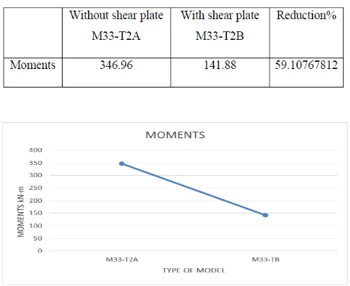
5.2.2 Moments (k N-M)
[image:4.595.42.271.134.327.2]The graph has been plotted for the moments of deep beam in M3-3 directions. In the graph, along X-axis ‘type of model’ has been plotted and along Y – axis ‘moments 3-3’ has been plotted. Below table shows the moments of type 2A and type 2B models.
Table 5: Shows the percentage reduction of moments for with shear plate and without plate
Graph 5: Variation of moments for without steel shear plate and for with shear plate condition
5.2.3 Shear Force (k N)
[image:4.595.311.557.376.577.2] [image:4.595.38.283.403.493.2]© 2017, IRJET | Impact Factor value: 5.181 | ISO 9001:2008 Certified Journal | Page 830 Table 6 : Shows the percentage reduction of shear force for
with shear plate and without plate
Graph 6: Variation of shear force for without steel shear plate and for with shear plate condition
5.3 Case 3: Deep beam with one end fixed and the other end is hinged
Fig 5: 3D model of deep beam showing fixed and hinged support
5.3.1Displacement (mm)
[image:5.595.39.288.134.385.2]The graph has been plotted for the vertical displacement of a deep beam. In the graph, along X-axis ‘meshing points’ has been plotted and along Y – axis ‘Displacement’ has been plotted. Below table shows the displacement of type 3A and type 3B models with percentage of reduction.
Table 7: Shows the percentage reduction of displacement for with shear plate and without plate
Graph7: Variation of displacement for without steel shear plate and for with shear plate condition
5.3.2 Moments (k N-M)
The graph has been plotted for the moments of deep beam in M3-3 directions. In the graph, along X-axis ‘type of model’ has been plotted and along Y – axis ‘moments 3-3’ has been plotted. Below table shows the moments of type 3A and type 3B models.
Table 8: Shows the percentage reduction of moments for with shear plate and without plate
[image:5.595.38.281.475.597.2] [image:5.595.313.559.580.733.2]© 2017, IRJET | Impact Factor value: 5.181 | ISO 9001:2008 Certified Journal | Page 831 5.3.3 Shear force (k N)
[image:6.595.314.556.169.439.2]The graph has been plotted for the axial loads of deep the beam. In the graph, along X-axis ‘type of models’ has been plotted and along Y – axis ‘moments 3-3’ has been plotted. Below table shows the moments of type 3A and type 3B models.
Table 9: Shows the percentage reduction of shear force for with shear plate and without plate
Graph 9: Variation of shear force for without steel shear plate and for with shear plate condition
5.4 Case 4: Deep beam with one end fixed and the other roller
Fig 6: 3D model of a deep beam with fixed and roller support
5.4.1 Displacement (mm)
The graph has been plotted for the vertical displacement of a deep beam. In the graph, along X-axis ‘meshing points’ has been plotted and along Y – axis ‘Displacement’ has been
plotted. Below table shows the displacement of type 4A and type 4B models with percentage of reduction.
Table 10: Shows the percentage reduction of displacement for with shear plate and without plate
Graph 10: Variation of displacement for without steel shear plate and for with shear plate condition
5.4.2 Moments (k n-M)
[image:6.595.43.286.228.430.2]The graph has been plotted for the moments of deep beam in M3-3 directions. In the graph, along X-axis ‘type of model’ has been plotted and along Y – axis ‘moments 3-3’ has been plotted. Below table shows the moments of type 4A and type 4B models.
[image:6.595.40.281.519.645.2]© 2017, IRJET | Impact Factor value: 5.181 | ISO 9001:2008 Certified Journal | Page 832 Graph 11: Variation of moments for without steel shear
plate and for with shear plate condition
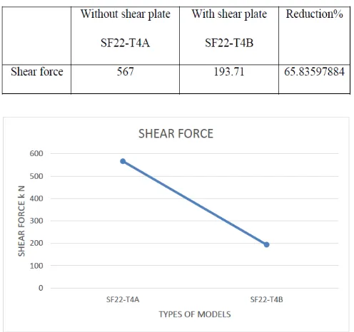
5.4.3 Shear force (k N)
[image:7.595.37.285.426.659.2]The graph has been plotted for the shear forces of deep the beam. In the graph, along X-axis ‘type of model’ has been plotted and along Y – axis ‘moments 3-3’ has been plotted. Below table shows the shear forces of type 3A and type 3B models.
Table 12 : Shows the percentage reduction of shear force for with shear plate and without plate
Graph 12: Variation of shear force for without steel shear plate and for with shear plate condition
Notations used and their abbreviations
U2 - Displacement in Y direction or Displacement at second meshing point
S11 - stresses in direction 1-1
S22 - stresses in direction 2-2 M33 - Moments in direction 3-3 P - Axial force
SF22 - Shear force in direction 2-2
(T1A) - Type 1A – Deep beam without steel shear plate (T1B) - Type 1B – Deep beam with steel shear plate (T2A) - Type 2A – Deep beam without steel shear plate (T2B) - Type 2B – Deep beam with steel shear plate (T3A) - Type 3A – Deep beam without steel shear plate (T3B) - Type 3B – Deep beam with steel shear plate
6. CONCLUSION
The following conclusions are drawn from the present study The results shows that the deep beam with steel shear plate is very effective as by using this steel shear plate there is a reduction in vertical displacement, bending moments, shear force, stresses and axial forces. So in other words there will be a reduction of main reinforcement (as bending moment is reduced), reduction of shear reinforcement (as shear forces are reduced), load carrying capacity is increased and size of the beam will be reduced.
6.1 Scope for further work:
1. Determining the effect of steel shear plate with web openings in deep beam by using equivalent static analysis 2. Determining the effect of steel shear plate for irregular deep beams
3. To study the effect of steel shear plate along deep beam with different types of loads like trapezoidal, point load.. etc
ACKNOWLEDGEMENT
I express my gratitude to my guide “Mrs Ranjitha K P", for her support, timely advice and encouragement provided to us during the period of our thesis work.
I hearty thanks to my bestie Meghashree T N who helped me to publish this journal.
REFERENCES
1) Jon Erik Moren investigated the “behaviour of reinforced concrete deep beams with shear deficiencies strengthened with different configurations of CFRP laminates”
2) J. Leon Raj, G. Appa Rao both studied the “Failure Modes of RC Deep Beam Panels”
3) Soo-Yeon SEO, Seung-Joe YOON, Woo-Jin LEE studied “Structural Behaviour Of R/C Deep Beam With Headed Longitudinal Reinforcements”
© 2017, IRJET | Impact Factor value: 5.181 | ISO 9001:2008 Certified Journal | Page 833 Rectangular Deep Beams with Fixed at Both Ends under
Uniform Load”
5) B.R. Niranjan, S.S.Patil carried out the work on “Analysis of RC Deep beam by finite Element method”