© 2017, IRJET | Impact Factor value: 5.181 | ISO 9001:2008 Certified Journal | Page 1288
Parametric Comparison of Rectangular and Trapezoidal Box Girder
Bridge Deck System
Pragya Soni
1, Dr. P.S. Bokare
21
Post graduate student in Civil Engineering, RSR Rungta college of Engineering and Technology, Bhilai (C.G.)
2
Principal and Professor in Civil Engineering, RSR Rungta college of Engineering and Technology, Bhilai (C.G.)
---***---
Abstract
- Bridge construction today has achieved a globalof importance. Bridges are the key elements in any road network. Among various types, use of box girder type bridges are gaining popularity in bridge engineering fraternity because of its better stability, serviceability, economy, aesthetic appearance, structural efficiency and rigidity in torsion. In this study, two different box girders bridge cross sections, rectangular and trapezoidal, are analyzed, designed and compared. The purpose of this study is to find out the efficient cross-section of box Girder Bridge. IRC 6:2014, IRC 21: 2000, IS 456:2000 and schedule of rates of public works department (Chhattisgarh) are used for the analysis. Finite element analysis is done using MIDAS civil 2016 Software package. It is observed from the study that trapezoidal cross section is cost effective than rectangular section. Central deflection in trapezoidal section is 7.6% more in trapezoidal section than in rectangular section. Shear force is less in trapezoidal section.
Keyword:
Torsional Rigidity, Box girder ,Finiteelement analysis.
1.
Introduction
Bridges are defined as structures which provide a passage over a gap without closing way beneath. They may be needed for a passage of railway, roadway, footpath and even for carriage of fluid. Bridge site should be so chosen that it gives maximum commercial and social benefits, efficiency and effectiveness. They shorten distances, speed-up transportation and facilitate commerce. Various types of bridge girder are adopted depending on span of piers. For span ranging from 20 m to 50 m box girder and T beam bridge girders are used. Box girders, have gained wide acceptance in freeway and bridge systems due to their structural efficiency, better stability, serviceability, economy of construction and pleasing aesthetics. Analysis and design of box-girder bridges are very complex because of its three dimensional behavior consisting of torsion, distortion and bending in longitudinal and transverse directions. Box girder comes with variations in cross section and in number of cells. If the depth of box girder
exceeds 1/6 or 1/5 of the bridge width then it is recommended to be designed as a single cell box girder bridge. If the bridge depth is smaller than 1/6 of the bridge width then a twin cell or multi cell box girder is provided, (Jorg Schlaich, 1982). In the present study two different
cross section of box girder are considered and their effectiveness in terms of economy is computed. Generally
box girders are in shape of rectangle, trapezium and circle. Among these shapes deflection is highest in circular girder and least in rectangular girder. (P.K. Gupta, 2010) .Bending moment and shear forces calculated on rectangular box girders are greater than that of trapezoidal cross section. (Satwik Mohan Bhat, 2016) There by design analysis is done for rectangular and trapezoidal section. Hence, the present study aims at analysis, design and comparison of two different box girder section for span of 29 m and width of 13 m.
2.
Methodology
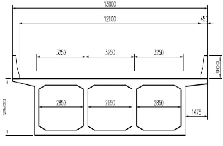
[image:1.612.340.560.513.657.2]Analyses of box girders are done on MIDAS Civil 2016 software. The different cross sections that are chosen are trapezoidal section and rectangular section. Cross section of both box girders are shown in figure below.
© 2017, IRJET | Impact Factor value: 5.181 | ISO 9001:2008 Certified Journal | Page 1289
Fig. 2 Trapezoidal SectionBoth the cross sections are idealized for finite element method. MIDAS is widely used finite element software for analysis of bridges. In MIDAS dynamic condition of loading can be modeled effectively. The analysis outcome of MIDAS is further used to design the sections manually, using working stress method by adopting code provisions of IRC 6:2014, IRC 21 :2000. Rate of particular grade of concrete and steel is obtained using schedule of rates by Public works department (Chhattisgarh).
3. Results
Two, 3 lane box girder of different cross sections are considered for design and analysis. Geometric drawings of the sections are prepared in AutoCAD and then it is imported in MIDAS civil 2016 software. MIDAS is a finite element software package for analysis of bridges. MIDAS is adopted for the analysis because of ease provided by it for application of live load on the girder. Grade of concrete used for girder is considered as M 40 and HYSD (Fe 500) bars are used as reinforcement in girder. As per IRC 6:2014 two type of load combinations for span ranging from 9.1 m to 13 m are considered (IRC:6, 2014). They are as follows-
1. 3 lane of Class A
2. One lane of Class 70R for every two lanes with one
lane of Class A on the remaining lane.
From the analysis it was observed that 3 lanes of class A loading is producing worst effect on the girder. So the girder is designed for 3 lanes of class A wheel loading. While doing transverse design cross section is divided into following structural members-
1. Cantilever slab
2. Continuous one way slab
3. Continuous one way bottom slab
4. Rib
For cantilever slab Class A loading is considered and for designing continuous slabs Class 70 R loading is considered where as for bottom slab only dead weight of slab and load due to maintenance is considered.
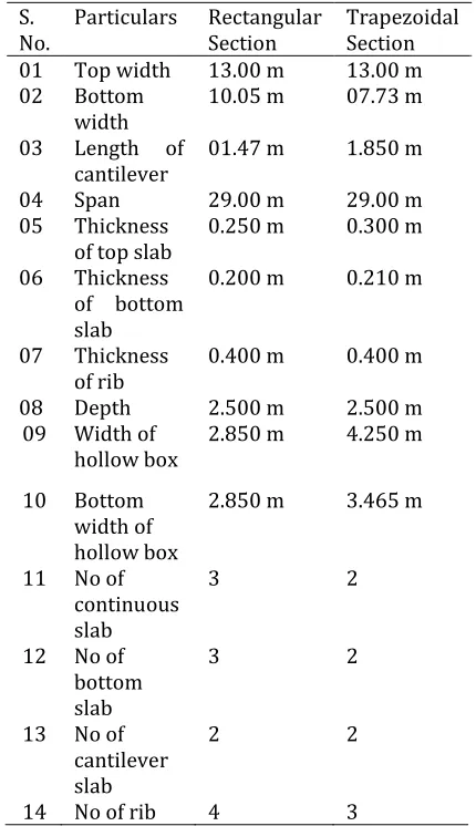
[image:2.612.342.557.257.630.2]Specifications of both the sections are as follows-
Table 1
S.
No. Particulars Rectangular Section Trapezoidal Section
01 Top width 13.00 m 13.00 m
02 Bottom
width 10.05 m 07.73 m
03 Length of
cantilever 01.47 m 1.850 m
04 Span 29.00 m 29.00 m
05 Thickness
of top slab 0.250 m 0.300 m
06 Thickness
of bottom slab
0.200 m 0.210 m
07 Thickness
of rib 0.400 m 0.400 m
08 Depth 2.500 m 2.500 m
09 Width of
hollow box 2.850 m 4.250 m
10 Bottom width of hollow box
2.850 m 3.465 m
11 No of continuous slab
3 2
12 No of bottom slab
3 2
13 No of cantilever slab
2 2
14 No of rib 4 3
© 2017, IRJET | Impact Factor value: 5.181 | ISO 9001:2008 Certified Journal | Page 1290
3.1.1 For Rectangular section-1. Bending Moment
Table 2
2.
Reaction at supportsTable 3
Support At L=0
m (kN) At L=29 m (kN) Outer most
support (1) 1246.1 1246.1
Inner
support (2) 1128.6 1128.6
Inner
support (3) 1134.7 1134.7
Outer most
support (4) 1265.6 1265.6
3. Central deflection-
Deflection due to worst combination of load i.e. DL+LL+SIDL on the bridge deck is observed at a distance of 14.5 m from the support. The magnitude of the maximum deflection is -14.070 mm.
4. Bending Stresses-
Due to loading conditions bending stresses are generated in the girder. Maximum bending stress is generated at the center of the span i.e. at 14.5 m from the either support. Magnitudes of bending stresses are as follows-
At top slab- -3.9 N/mm2
At bottom slab- 5.1 N/mm2
5. Shear force-
4526.7 kN
3266 kN
Fig. 3 Maximum shear force in longitudinal direction for rectangular cross section
3.1.2
For Trapezoidal section-
1. Bending Moment-
Table 4
2.
Reaction at supports-
Table 5
Support At L= 0 m (kN) At L= 29 m (kN)
Outer Support
(1) 1550.00 1150.00
Mid support (2) 1500.56 1500.56
Outer support
(3) 1475.00 1475.0 0
3. Central deflection-
Deflection due to worst combination of load i.e. DL+LL+SIDL on the bridge deck is observed at a distance of 14.5 m from the support. The magnitude of the maximum deflection is -15.203 mm.
Type of Loading Dead load
Bending Moment (kN-m)
SIDL Bending Moment (kN-m)
Live load Bending Moment (kN-m)
3 lanes of Class A 19264 4410 8591
One lane of Class 70R for every two lanes with one lanes of Class A on the
remaining lane
19264 4410 6364
Type of Loading Dead load Bending Moment (kN-m)
SIDL Bending Moment (kN-m)
Live load Bending Moment (kN-m) 3 lanes of Class
A 18359 4410 8591
One lane of Class 70R for every two lanes with one lanes of Class A on the remaining lane
© 2017, IRJET | Impact Factor value: 5.181 | ISO 9001:2008 Certified Journal | Page 1291
4. Bending Stresses-Due to loading conditions bending stresses are generated in the girder. Maximum bending stress is generated at the center of the span i.e. at 14.5 m from the either support. Magnitudes of bending stresses are as follows-
At top slab = -3.7 N/mm2
At bottom slab = -5.8 N/mm2
5.
Shear Force-
4401kN
3266.2 kN
Fig.4 Maximum shear force in longitudinal direction for rectangular cross section
3.1.3 Transverse section is designed manually and from the results final comparison between consumption of steel and concrete can be done.
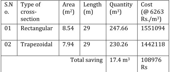
Quantity of concrete required for each cross section can be computed as-
[image:4.612.29.301.506.622.2]
Consumption of concrete-
Table 6
Rate of concrete is taken from Schedule of rates published by public works department (Chhattisgarh).Rate of M40 grade concrete is 6263 Rs. per cubic meter.
Consumption of
steel-From the manual calculation Weight of steel member are calculated . Cost deployed in steel is calculated by multiplying it by rate of steel for HYSD bars mentioned in Schedule of rates ,published by Public works department (Chhattisgarh).Cost of HYSD steel is 41500 Rs /MT. Weight of steel required for both the cross section and their cost analysis are tabulated as-
Table 7
S. No Type of cross
section Weight (kg) Cost (Rs)
1 Rectangular 154591.71 6415526.5
2 Trapezoidal 115341.55 4786651
Total 1628875
4
Conclusion
From the results obtained from the design and analysis following conclusions are drawn-
1. Consumption of concrete and steel is more in
rectangular section than in trapezoidal section. Hence, cost of concrete is 7% less and steel is 25% less in trapezoidal section when compared to rectangular section.
2. Number of pedestal required is less in trapezoidal
section which reduces the cost of pedestal and in future cost of maintenance will also be reduced.
3. Central deflection in trapezoidal section is 7.06%
higher than that of rectangular section. (Satwik Mohan Bhat, 2016) also observed that for the same section properties deflection is more in trapezoidal section.
4. Shear force is more in rectangular section. Similar observation was also noted by (Satwik Mohan Bhat, 2016) that box girder having two different cross section but same width and span than shear force will be higher for the rectangular cross section.
5. Use of trapezoidal section will increase aesthetic appearance of the bridge.
S.N
o. Type of cross-section
Area (m2)
Length
(m) Quantity (m3)
Cost (@ 6263 Rs./m3)
01 Rectangular 8.54 29 247.66 1551094
02 Trapezoidal 7.94 29 230.26 1442118
Total saving 17.4 m3 108976
© 2017, IRJET | Impact Factor value: 5.181 | ISO 9001:2008 Certified Journal | Page 1292
5
Future scope
1. Detailed designed of efficient section can be done. Though the depth is more and section is designed as singly reinforced section as scope of this study was only to identify the efficient section among two, so for the further studies section can be redesigned by minimizing its depth and designing it as doubly reinforced section or designing it as PSC bridge.
2. Width of rib is considered as constant throughout the
span it can also be changed as higher on supports and lower at center.
Reference-
1. IS 456:2000, PLAIN AND REINFORCED CONCRETE
- CODE OF PRACTICE. New Delhi: Bureau of Indian Standard.
2. Dr. B.C.Punmia, A. K. (2006). R.C.C. Design. New Delhi: Laxmi Publication (P) LTD.
3. Dr. I.C. Syal, D. K. (2013). Reinforced Concrete Structures. New Delhi: S.Chand & Company Ltd.
4. IRC:6. (2014). Loads and stresses. New Delhi:
Indian Roads Congress.
5. IRC21. (2000). Cement Concrete (Plain and
Reinforced). New Delhi: Indian road congress.
Bridges. IABSE.
7. Krishnaraju, N. (2010). Advanced Design of
Reinforced concrete structure (IS 456:2000). New Delhi: CBS Publication.
8. 8) P.K. Gupta, K. K. (2010). PARAMETRIC STUDY
ON BEHAVIOUR OF BOX-GIRDER. ASIAN JOURNAL OF CIVIL ENGINEERING (BUILDING AND HOUSING) , 135-148.
Design of Prestressed Box Girder Bridge by IRC: 112-2011. International Journal of Constructive Research in Civil Engineering , 1-10.
10. 10) PWD. (2015). Schedule of rates for bridges. Raipur: Public Works Department ,Chhattisgarh.
11. 11) Satwik Mohan Bhat, A. K. (2016).
Comparative Study of Rectangular and
Trapezoidal Concrete Box Girder using Finite Element Method. Journal of Civil Engineering and Environmental Technology , 489-494.
6. Jorg Schlaich, H. S. (1982). Concrete Box-girder