http://dx.doi.org/10.4236/eng.2014.612073
How to cite this paper: Lee, H.-T., Tsai, H.-L., Chen, Z.-Q. and Jiang, Y.-T. (2014) Mobile Detecting Robot Controlled by Smartphone Based on iOS. Engineering, 6, 750-757. http://dx.doi.org/10.4236/eng.2014.612073
Mobile Detecting Robot Controlled by
Smartphone Based on iOS
Hou-Tsan Lee
*, Hsiang-Lin Tsai, Zhong-Quan Chen, Yu-Ting Jiang
Department of Information Technology, Takming University of Science and Technology, Taipei, Taiwan Email: *[email protected]
Received 31 August 2014; revised 20 September 2014; accepted 8 October 2014
Copyright © 2014 by authors and Scientific Research Publishing Inc.
This work is licensed under the Creative Commons Attribution International License (CC BY). http://creativecommons.org/licenses/by/4.0/
Abstract
The proposed scheme is composed of a smartphone, a vehicle equipped with Wi-Fi module and an IPCam working as a detecting robot to explore the unknown environment. Besides, another ve-hicle equipped with Wi-Fi module is also developed as a trunk robot to extend the detecting range. On the other hand, these vehicles are designed to be driven by the smartphone based on iOS (an iPod Touch in the experiments) via Wi-Fi module along with some proper designs of control cir-cuit mounted on the vehicles. By the audio-visual feedback signals from IPCam, the real-time sce-nario from the detecting area not only can be shown on the screen of the smartphone but also provides the information of the detected environment in order to guide the robot. Two control approaches were provided in the proposed control scheme, the touch-panel control and the smartphone-status control, to drive the vehicles with the help of visual feedback on the screen of the smartphone. Moreover, the trajectories of the robots were also recorded for further applica-tions. Some experimental results are given to validate the satisfactory performance of the pro-posed control scheme.
Keywords
Mobile Robot, Smartphone Controlled, iOS, Wi-Fi
1. Introduction
The application of robotic systems which addresses fundamental issues in coexistence of surveillance and robots from psychological and philosophical aspects over interaction and communication mechanisms of architectures and technological systems is popular nowadays [1]-[5]. In these materials, not only wireless networks were ap-plied in these proposed systems but also mobile vehicles were considered to play a role as the carriers of other
successful applications of combining the robotic systems [6]-[10]. This work focused on the purpose of combing smartphone and robot by Wi-Fi system as well as the visual feedback from IPCam was also via Wi-Fi system. Meanwhile, the proposed system accompanied with the fast development of smartphone. As we known, using smartphone to drive a vehicle is also an interesting subject [11]-[13]. With the visual feedback from the IPCam mounted on the vehicle, the smart phone can send the control signals to the control circuit with the help of Wi-Fi system and drive the robot to any desired positions within a certain area as well as the images of the detecting area can be fed back to the smartphone. The proposed scheme not only provides the functions mentioned pre-viously but also shows the real-time images on the screen of the smartphone which come from the IPCam mounted on the robot. This proposed paper also provides two methods to control the vehicle, one is developed based on sensing the accelerometer inside the smartphone and the other is the touch-panel control, to detect the unknown area by the audio-visual feedback from the IPCam with the help of Wi-Fi communication system. Furthermore, a trunk robot was also developed to work as an access point in the wireless network to extend the working range of the detecting robot. The proposed wireless network is not the infrastructure mode but the ad hoc mode, iOS system is chosen as the operation system of the smartphone for implementation.
2. System Architecture
As shown in Figure 1, the overall system is simply demonstrated. There are a smartphone, a vehicle with a Wi-Fi module and an IPCam mounted on the vehicle in Figure 1(a). These three devices are connected by Wi-Fi system using Adhoc wireless network structure to access data among these devices. Figure 1(b) gives a sketch of overall system of the proposed system to demonstrate the relationships among smartphone, the trunk robot and the detecting robot. The dot lines only work when the smartphone lost signals with the detecting robot. In that case, the smartphone requires the communication with the detecting robot via the trunk robot.
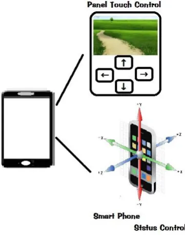
The proposed control methods of the vehicle can be demonstrated as shown in Figure 2 below. Both the touch-panel control by pre-design program and the smartphone-status control by the accelerator inbuilt were given with real time image feedback provided by the IPCam mounted on the vehicle. Thus, the detecting robot was developed and implemented. The trunk robot was also implemented as the detecting robot but the IPCam.
3. Hardware Implementation
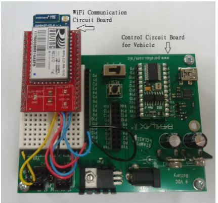
In this proposed scheme, Figure 3(a) shows an iPod Touch (or iPhone) by Apple Co. which was chosen to play the role as the smartphone. The wireless network camera produced by D-link Co. was adopted as the IPCam in the proposed system as shown in Figure 3(b). With the help of control circuit board with BS2 microprocessor insidetodrive the vehicle and the Wi-Fi module communication circuit board being fabricated as shown in
Figure 4, the control signals were sent from iPod Touch to the Wi-Fi module on the vehicle and then
transmit-ted to the control board also mountransmit-ted on the vehicle to drive the robot from place to place as same as the au-dio-visual information from the IPCam being sent back to iPod Touch.
Figure 5 below shows the original platform of the vehicle with two DC motors and an omnidirectional wheel
in the front. After proper alignment and assembly, the vehicle with Wi-Fi module and IPCam will be imple-mented to work as a mobile detecting robot.
After completing the assembly of the robot, the realized detecting robot was fulfilled as shown in Figure 6. The side view is given in Figure 6(a) to demonstrate its appearance with approximate size of 20 × 12 × 22 cm and the top view of the detecting robot was also provided to show the Wi-Fi module, the control circuit and the conducting wires in Figure 6(b).
4. Experimental Results
1) The Image Feedback(a)
[image:3.595.166.461.86.432.2](b)
Figure 1. The sketch of overall system. (a) Detecting robot only; (b) Detecting robot and trunk robot.
[image:3.595.222.403.468.698.2](a) (b)
[image:4.595.206.422.305.506.2]Figure 3. The photos of iPod Touch and IPCam. (a) iPod Touch by Apple Co.; (b) IPCam by D-Link Co.
Figure 4. The control boards of vehicle and Wi-Fi module.
[image:4.595.207.421.536.707.2](a) (b)
Figure 6. The realization of the proposed detecting robot. (a) Side view of the robot; (b) Top view of the robot.
(a) (b)
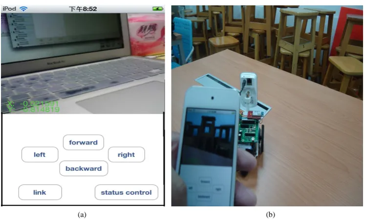
Figure 7. The touch panel control of detecting robot. (a) The display of the smartphone; (b) An indoor experiment of touch panel control.
shown in the upper half of the screen of the smartphone and the lower half is divided into three touch groups: a) the touch-panel control group included forward, backward, left, and right button to drive the robot in different directions, b) the “link” button was given to connect the devices by Wi-Fi system, and finally c) the “status con-trol” button is also provided to switch the controlled robot form touch-panel to smartphone status-control. The status-control was designed to drive the vehicle by changing the status of the smartphone and then obtains a set of numbers in different coordinates by the inbuilt accelerometer of the smartphone. With the changing numbers in different coordinates, a control program was designed to send the control commands to the control circuit board mounted on the vehicle to drive the car in different direction and speed. An indoor experiment was con-ducted to demonstrate the performance of the mobile detecting robot as shown in Figure 7(b). In the experiment, not only the image in front of the robot was shown on the screen of the smartphone but also the robot was driven by the touch-panel of the smartphone with proper arrangement of the pushing sequence of buttons.
2) The Touch Panel Control and the Satus Control of the Robot
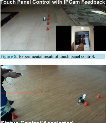
In Figure 8, the user can control the mobile detecting robot moving in different directions easily. By changing
[image:5.595.127.501.267.493.2]detect-the trunk robot, which was lack of IPCam, moved toward detect-the detecting robot. The display of detect-the smartphone showed the previous image from the detecting robot. Within a certain range between trunk robot and detecting robot, the communication restored and the smartphone controlled the detecting robot again as same as the image regained from the IPCam as shown in Figure 10(b).
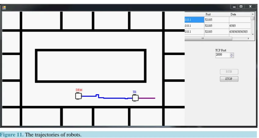
[image:6.595.169.462.278.650.2]Another approach of the proposed system was the trajectories of robots, which recorded the paths of robots, stored in the database of a notebook computer also within the Wi-Fi wireless network. Figure 11 shows the tra-jectories of the detecting robot (DRM in blue line) and the trunk robot (TR in red line). The tratra-jectories of robots can help users to track the paths of rescue process to avoid repeating searching and increase the efficiency of rescue. Besides, the trajectory of detecting robot is crucially important as dispatching the trunk robot.
[image:6.595.206.420.281.529.2]Figure 8. Experimental result of touch panel control.
Figure 9. Experimental result of satus control.
(a) (b)
[image:6.595.113.525.563.706.2]Figure 11. The trajectories of robots.
5. Conclusion
Bringing robots as assistants to detect the unknown area or dangerous places is very important now and in the future. In order to keep users away from danger, the mobile detecting robot was therefore developed in the pro-posed system. This work had successfully developed the mobile detecting robot with the IPCam mounted on the vehicle to feedback the real time image in front of the robot which can help user to make better decisions not only to control the vehicle but also to realize the real time scenario of the detecting area. By the help of the Wi-Fi communication system, the communication among the IPCam, the iPod Touch and the robot can be suc-cessfully developed. On the other hand, applying the data of the inbuilt accelerometer of iPod Touch can make the vehicle control not only directly by touch panel control but also by changing the status of iPod Touch. Thus, a bi-mode of smartphone-status controlled and touch-panel controlled mobile detecting robot is therefore devel-oped. Moreover, with the help of visual feedback information from the IPCam mounted on the vehicle, the user can control the vehicle and detect the unknown area by watching the display of iPod Touch. With the proper ar-rangement of the wireless Wi-Fi network e.g. adding the trunk robots, the working area of the proposed detect-ing robot can expand within a reasonable range. In the proposed system, a trunk robot was also developed to deploy in the field to extend the range of working area of the detecting robot. Most of all, the proposed detecting robot can be used in a dangerous environment to perform a searching task or a dangerous exploration. For ex-amples, it can detect the existence of lives in ruins after earthquake or the real time image of a bomb threat. On the other hand, it can be used to patrol a certain area to identify the intruders by the IPCam. The trajectories of robots can be also recorded in the computer with the help of the Wi-Fi wireless network. Furthermore, combing other equipment mounted on the vehicle e.g. robotic arm, some simple tasks maybe performed in the near future. Some experimental results were given to demonstrate the performance of the proposed system.
Acknowledgements
This work is partially supported by the Project NSC-101-2221-E-147-002 in Taiwan. The author also thanks Jia-Xing He and Yu-Chi Lin for their efforts in the experiments.
References
[1] Lee, H.-T., et al. (2012) Mobile Detecting Robot with IPCam Feedback. Proceedings of SICE Annual Conference, Akita, 20-23 August 2012, 1969-1973.
[2] Yu, M.-S., Wu, H. and Lin, H.-Y. (2010) A Visual Surveillance System for Mobile Robot Using Omnidirectional and PTZ Cameras. Proceedings of SICE Annual Conference,Taipei,18-21 August 2010, 37-42.
Com-Cellular Backhaul Network in Emergency Situations. 1st International Conference on Wireless VITAE 2009,Aalborg, 17-20 May 2009, 525-529.
[7] Xavier, B. and Christensen, L. (2006) Cellular/Wi-Fi Multi-Mode Systems. 2006 IEEE Radio and Wireless Symposium, 17-19 January 2006, 3-6. http://dx.doi.org/10.1109/RWS.2006.1615080
[8] Bappu, B., Tay, J. and Obradovic, M. (2005) Incentives Evaluation in 2-Hop Relay enabled Wi-Fi Hotspots.
EUROCON 2005, Belgrade, 21-24 November 2005, 1834-1837.
[9] Kim, J.-O., Tanigawa, Y. and Tode, H. (2010) Enhancing Downlink Multimedia QoS in Wi-Fi Hotspot Networks. 8th IEEE International Conference on Industrial Informatics (INDIN),Osaka, 13-16 July 2010, 1049-1053.
[10] Niyato, D. and Hossain, E. (2007) Wireless Broadband Access: WiMAX and Beyond—Integration of WiMAX and Wi-Fi: Optimal Pricing for Bandwidth Sharing. IEEE Communications Magazine, 45, 140-146.
http://dx.doi.org/10.1109/MCOM.2007.358861
[11] Mostofi, Y. (2012) Cooperative Wireless-Based Obstacle/Object Mapping and See-Through Capabilities in Robotic Networks. IEEE Transactions on Mobile Computing, 12, 817-829.
[12] Zhao, Y.-G., Cheng, W. and Liu, G.-L. (2012) The Navigation of Mobile Robot Based on Stereo Vision. Fifth Interna-tional Conference on Intelligent Computation Technology and Automation (ICICTA),Zhangjiajie,12-14 January 2012, 670-673.