© 2016, IRJET | Impact Factor value: 4.45 | ISO 9001:2008 Certified Journal
| Page 576
Squeal Analysis of Disc Bake
Prof. C.S. Wadageri
1, Prof A.M. Hulagabali
2, Prof. Santosh Malipatil
31
Head of Department Maratha Mandal Engineering Collage, Belagavi
2
Professor at Maratha Mandal Engineering Collage, Belagavi
3
Professor at Maratha Mandal Engineering Collage, Belagavi
---***---Abstract -
It is well-known fact that automobile brakes generate several kinds of noises like squeal, groan, chatter, judder, moan, hum and squeak. Squeal is the most prevalent, annoying and can be reduced by variations in geometry, parameters such as coefficient of friction, stiffness of material. The brake squeal generally occurs in the range of 1-16 kHz. Basically two methods are available to study the disc brake squeal, namely complex eigenvalue analysis and dynamic transient analysis. Complex eigenvalue analysis is the standard method used for squeal analysis. Analytically it is very difficult to solve because of complex brake mechanisms. Experimental and numerical techniques have been developed by various researchers in order to study brake squeal. Experimental techniques are unable to predict brake squeal at the early stages of design process and also very costly due to associated design iterations. Therefore, finite element analysis has emerged as a viable approach for brake squeal analysis. This work presents Finite Element modeling and modal analysis of disc-pad assembly using high end software tools. Linear non-pre-stressed modal analysis and full nonlinear perturbed modal analysis is applied to predict frequency at which squeal occurs. Real and imaginary Eigen frequencies of unstable modes are obtained. Analysis is performed by varying the coefficient of friction and outer diameter of disc pad assembly. Increasing friction coefficient has no desirable effect on squeal frequency while squeal propensity decreases as the outer diameter of disc is increased.Key Words: Brake Squeal, Eigen Frequency, Squeal analysis, FEM, Natural Frequency, Mode Shapes
1. INTRODUCTION
The brake noise reductions are needed because of comfort rather than performance and safety of car. Most of the refinement is done in other parts like transmission, suspension and passenger sitting acoustics. So attention must be made to reduction of noise coming from brake. Legal rules are made for continuous noise coming from vehicle and they do not include noise coming when brake is applied. Since if we reduce the noise level coming from brake it is better for environment and noise level is low where frequent stopping of vehicle takes place, for example near road brakes. Disc brake vibration problem is classified into two groups. First type is like jerk; it occurs but can’t hear because
its frequency is below the 100 Hz. In second type is occurred due to self-excitation of oscillation. This type of noise is audible because its frequency is above the 1 KHz and it is termed as ‘squeak’ or ‘squeal’.
© 2016, IRJET | Impact Factor value: 4.45 | ISO 9001:2008 Certified Journal
| Page 577
There are some theories tried to explain disc brake squeal, some are listed below.
1.1 Variable Friction Model
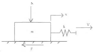
[image:2.595.80.239.235.323.2]Sinclair made an experiment, his experiment consists of mass indicated by M, and applied load is indicated by N, is pulled using spring having stiffness indicated by K, and friction force acting during sliding motion is indicated by F. The other end of spring will have constant velocity V; static coefficient of friction is greater than kinetic coefficient of friction.
Fig -1: Sliding block on plane
From deep study they found that static coefficient of friction is more than kinetic coefficient of friction i.e. µs > µk. Relation between µs & µk is given by
µk = {( µs- µh) / ( 1 + d V )} + µh
Where, µh and d are friction material constants. V is bocks initial velocity
c < { {L d (µk- µk)} / { ( 1 + d V) ( 1 + d (V – V1)) }} From above equation it is found that, kinetic and static coefficient of frequencies has very big difference. Low sliding speeds and large normal loads will all enhance squeal.
1.2
Experiment to find Component Dynamic
relation with Squeal
Different approach is made by Shah and Lewis in which mechanism and source of brake squeal are isolated. According to them squeal of frequency 7250 Hz is produced when disc vibration and pad deflection are in phase. From there experiment natural frequency under static condition is up to 6500 Hz which is nearer to squealing frequency i.e. 7250 Hz. Above experiment is repeated by changing clamp and discs of brake. Resonance occurred subsystem of pad and caliper at squeal frequency, pressure is increased further because of higher frequency resonance of the system. From analysis (modal) it has been observed that first and fifth bending modes of pad occurred at 6250 Hz and 6500 Hz. Global system of squeal resonance is formed when localized disc resonance coincides with line pressure, pad localized resonance. Adding of mass to pad will alter the natural frequency. Also squeal suppression is made by altering the content brake pad i.e. adding of damping material. Hoffman found that, modifying the brake pad with damping material is possible within operative vibration and temperature range of squealing disc brake.
1.3 Experiment to find relation between Squeal and
contact stiffness
‘Hany et al’ used a glass apparatus to analyze the squeal noise which was generating continuously. By changing the surface finish we can easily get the necessary conditions that are needed for squeal producing. The factors affected by normal loads are given below:
a) Sound pressure can be increased in range 30-100N b) Squeal frequency can be obtained by changing the load on glass plate for example 9025 Hz at 30N and 9216 Hz at 90 N. Materials having high modulus friction are used to obtain high rigidity of disk in normal direction and sound pressure level can be reduced with increased radius of contact. During squeal condition friction force is high and is low in no squeal condition
Squeal increases as normal and tangential contact stiffness increases as per above assumption. Longitudinal vibration which leads to squeal is designed analytically by Hany using above principle. Asperities of disc and pad interference will cause the tangential and normal contact stiffness, which were modeled as mass less spring. Boundary stability are determined by Hurwitz-Routh criterion using characteristic equation. Wide, short and thick pads, high modulus of elasticity etc parameters tend to reduce the squeal according to numerical results. Nevertheless the longitudinal vibration predicted by the model remained dependant on the slope of the friction coefficient - velocity relationship.
1.4 Conclusions from Literature Review
(a) High coefficient of friction will cause reduction in velocity and energy of system gets converted into amplitude of motion which will causes the instability leads to squeal... (b) Dynamic instability resulting in squeal of the disc brake system can arise from favorable dynamic and geometric conditions, even when the coefficient of friction does not vary with the sliding velocity. Thus (a) is not a necessary condition for squeal to occur.
(c) Frictional force can be correlated with displacement of pad and disc as variable force which is also proportional to contact stiffness.
(d) Investigation of brake squeals by FEM approach very suitable and complex formulations are done easily.
© 2016, IRJET | Impact Factor value: 4.45 | ISO 9001:2008 Certified Journal
| Page 578
2. FINITE ELEMENT MODEL OF DISC BRAKE
2.1 CAD modeling of disc brake
Disc brake three dimensional models are made in 3D modeling softwares like Catia V5, Pro E or Autodesk Inventor. The disc brake model is saved in ‘igs’ format. ‘igs’ format is the universal format which can be opened using any modeling or meshing software.
2.2 Meshing of Disc Brake
[image:3.595.308.554.189.320.2]Disc brake geometries are imported in hyper mesh using import geometry option. After importing geometry, solid meshing or 3D meshing is done using 8 noded hexa elements and 6 noded penta elements. 3D meshing is done using meshing command ‘solid mesh’. In solid meshing command various flexible options are given for meshing. We can use the suitable options for meshing purpose based on the geometry of component. For example, in ‘general’ command we can define mesh pattern at start face and end face also. Also we can specify the path of mesh flow. While specifying path we can take help of lines, face and points as a reference or path the mesh should follow. While meshing we can slit the geometry based on complexity and maintain the flow of mesh. In solid meshing only we have some other meshing commands like line drag, linear solid, ends only, one volume, multi solids etc.
Fig -2: Disc brake mesh model with pad
2.3 Surface Contact
The Bulk Data pair BCBODY/BSURF to designate the type of contact body (deformable) and the elements comprising the contact body. The contact algorithms locate the element faces that will potentially participate in contact surfaces. There is no need for user effort to limit the elements listed on the BSURF entry to aid the contact algorithms.
Additional contact bodies are permitted. With disk brake systems, other components would be (but not limited to) the caliper, pistons, guide pins, and steering knuckle. The BCTABLE collects the contact bodies and assigns various parameters related to the surface contact.
2.4
Boundary Conditions
Pads are constrained to restrict translation about x and y direction, Z direction translation kept free.
[image:3.595.36.282.427.568.2]At bolt location translation about all direction i.e. x, y and z are constrained.
Fig -3: Boundary conditions applied for pad
3. FINITE ELEMENT ANALYSIS OF DISC BRAKE
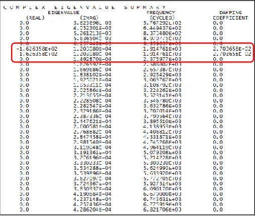
Once solution is done then, complex eigenvalue summery of analysis is displayed in note pad file as shown below. Its contains real and imaginary eigen values, frequency and damping coefficient.
Fig -4: Complex Eigen value Summary
In above output we can observe that 6th and 7th mode’s
are unstable modes with frequency 1914.54 Hz for disc brake contact surface having coefficient of friction 0.3.
[image:3.595.309.563.444.660.2]© 2016, IRJET | Impact Factor value: 4.45 | ISO 9001:2008 Certified Journal
| Page 579
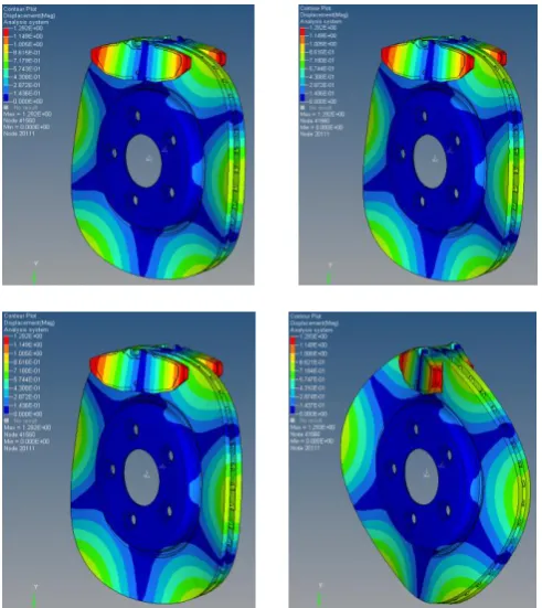
and produce a squealing noise. When linear non- pre-stressed modal analysis is performed the obtained mode shape plots for unstable modes are shown below.
[image:4.595.35.281.154.430.2]
Fig -5: Mode shapes of disc brake at 0.5 coefficient of friction and pressure applied 10%, 30%, 50% and 100% sequentially
Table -1: Results for 0.5 coefficient friction
Squeal Analysis Result for 0.5 coefficient of friction
Load % 10% 20% 50% 100%
Real Frequency (Hz)
1628.014 1627.829 1627.272 1626.358
Damping coefficient -0.02706 -0.02705 -0.02705 -0.02703
Above mentioned are 1st Unstable Frequency Modes
in Brake Squeal Analysis. The frequencies are falling in the range of 1 to 5 KHz; hence it shows the effect of “Low Frequency Squeal”.
So from above results it is clear that for coefficient frequency 0.5, 1628.014, 1627.829, 1627.272 & 1626.358 are the eigen frequencies for 10%, 30%, 50% & 100% loads respectively which will cause squeal.
4. EXPERIMENTAL SQUEAL TEST
Here use of brake test rig machine for testing of disk brake squeal is discussed and is shown in below figure [18]. The main aim of this experiment is to find brake squeal at different coefficient of friction and different value of applied pressure. And obtained results are compared with FEM results. Here experiment is divided into three parts. In first part, setup is explained thoroughly; explaining of squeal test is done in second part. Last part contains results.
Fig -6: Layout of the brake test rig
[image:4.595.308.564.239.358.2]© 2016, IRJET | Impact Factor value: 4.45 | ISO 9001:2008 Certified Journal
| Page 580
Fig -7: Experimental test result Sound frequency Vs frequency (At 0.5 coefficient of friction and 100% load)
5. RESULT COMPARISON AND VALIDATION
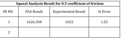
Squeal analysis of the disc brake assembly is performed by varying the coefficient of friction between disc and pad. Here experiment is made for co efficient of friction 0.5 and for 100% load. Following table shows comparison of experimental and FEA results.
Table -2: Comparison of FEA and Experimental results
Squeal Analysis Result for 0.5 coefficient of friction
SR NO FEA Result Experimental Result % Error
1 1626.358 1652 1.52
2
The FEA (NASTRAN) result gives squeal frequency at 1626.358 Hz while results experimentally show that the squeal occurs at the frequency 1652 Hz. It is quite near to FEA results. Hence, error of FEA results is 1.57%. This shows that the squeal problems can be solved by NASTRAN with less error
6. CONCLUSION
[1] As load on brake increases the Eigen frequency decreases.
[2] As load on brake increases the damping coefficient increases.
[3] When the coefficient of friction is increased from 0.3 to 0.5, the real eigen-frequency decreases.
[4] Finite Element Analysis result error is 1.57% which is within the acceptable limit.
REFERENCES
[1] Crolla, D A. and Lang, A.M. “Brake Noise and Vibration - The State of the Art” , Vehicle Tribology , Leeds-Lyon 17, Tribology Series 18, (Dowson, D. ; Taylor, C M. and Godet, M. , ed.) Elsevier Science Pub., Sept. 1991, pp. 165 -174.
[2] ‘Case for Support” Internal Report of Mechanical Engineering Department, Leed University, Sept. 1990. [3] ‘WHICH? CAR-Guide to New and Used Cars 1995’,
Consumer Association, London 1995.
[4] Smales, H “Friction Materials - Black Art or Science”, Proc. I.Mech.E. Vol. 209, No. D3 , Part D : Journal o f Automotive Engineering, 1995, pp. 151 -157.
[5] Murakami, H.; Tsunada, N.;Kitamura, M. “A Study Concerned With Mechanism of Disc brake Squeal”, SAE Paper 841233.
[6] Fieldhouse, J.D. and Newcomb, T.P. “An Investigation Into Disc Brake Squeal Using Hologrpahic Interferometry”, 3rd Int’l EAEC Conference on Vehicle Dynamics and Powertrain Engineering - EAEC Paper No. 91084, Strasbourg , June 1991
[7] Lamarque, P.V. “Brake Squeak: The Experience of Manufacturers and Operators: Report No. 8500B” Inst. Auto. Engrs. Research and Standardisation Comittee 1935.
[8] Fosberry, R A C. and Holubecki, Z. “An Investigation of the Causes and Nature of Brake Squeal” , MIRA Report 1955/2.
[9] Fosberry, RAC and Holubecki, Z. “Some Experiments on the Prevention of Brake Squeal” , MIRA Report 1957/1. [10] Fosberry, R.A.C. and Holubecki, Z. “Third Report on
Squeal of Drum Brakes", MIRA Report 1957/3.
[11] Fosberry, R.A.C. and Holubecki, Z. “Disc Brake Squeal: Its Mechanism and Suppression”, MIRA Report 1961/2.
[12] Sinclair, D. “Frictional Vibrations”, Journal o f Applied Mechanics, 1955, pp 207 -214.