http://dx.doi.org/10.4236/ica.2014.53012
A Study on Autotuning Controller for Servo
System
Nguyen Hoang Giap1, Jin-Ho Shin2, Won-Ho Kim2
1Department of Intelligent System Engineering, Graduate School of Dong-eui University, Busan, Korea 2Department of Mechatronics Engineering, Dong-eui University, Busan, Korea
Email: [email protected], [email protected], [email protected]
Received 16 May 2014; revised 20 June 2014; accepted 3 July 2014
Copyright © 2014 by authors and Scientific Research Publishing Inc.
This work is licensed under the Creative Commons Attribution International License (CC BY).
http://creativecommons.org/licenses/by/4.0/
Abstract
This paper introduces a PID Autotuning controller using intelligent neural network control based on relay feedback approach. The proposed controller takes advantage of offline learning, in which the initial knowledge of control system is recognized by the relay feedback approach, and the on-line learning capability of neural network controller helps the control system respond quickly to the dynamics changes. The robustness and motion tracking performance are validated through simulation results.
Keywords
PID, Neural Network, Relay Feedback
1. Introduction
Several control design approaches have been developed as independent sub-fields of motion control domain, such as adaptive control, robust control, model predictive control, lead-lag compensation. However, controller of PID type is the most commonly used in motion control [1]. Numbers of tuning methods for PID controller have been introduced since Ziegler and Nichols published their PID tuning rule in 1942. And until now it is still one of the most popular schemes. In this method, the control rules are defined by the ultimate gain and period, which are obtained by observing the oscillation of proportional closed-loop controller. This proposed scheme is difficult to carry out in motion control application since the amplitude of the oscillation is hard to keep under control.
find the PID control parameters from the calculated ultimate gain and period based on desired amplitude margin, the result is not optimum.
Conventional PID controller is well-suited for the linear control system which behaves in a predictable way. However, the parameters of PID controller are difficult to adapt to a wide range of uncertainty. Therefore, the robustness and performance of PID deteriorate in some industrial control applications, where the systems are normally subjected to rapid and unpredictable ways. Consequently, it is mandatory to incorporate the intelligent control function to the PID controller to adapt with the dynamics change of the control system. There are several researches and commercial products which apply such advance functions [6]-[12].
In [13], a phase locked loop identifier is designed to solve different open-loop frequency domain non-para- metric identification problems by giving exact estimation of the gain crossover point. In [14], the author presents a new strategy of PID autotuning based on the combination of relay feedback methodology and operational op-timization. For the operational optimization, data base of the control system is generated to develop the radial basis function network model. This model is applied to a nonlinear program to obtain the optimized control output. The relay feedback is applied to obtain the ultimate gain and frequency of control system. Then, the op-erating regions are separated, and the process data generated in the previous step are used to identify the fre-quency response model for each operating region.
In this research, we introduce an autotuning of PID controller based on radial basis function neural network (RBFNN) and relay feedback approach. The controller is designed as follows: firstly, the relay feedback control is carried out to analyze the system dynamic and calculate the ultimate gain and ultimate frequency of the con-trol system by measuring the output amplitude and period; then a RBFNN with gradient descent algorithm is de-signed to approximate the system dynamic. Finally, the ultimate gain and ultimate frequency are incorporated in the neural network to adjust the coefficients related to the PID control parameters.
2. Design of PID Autotuning Controller
2.1. Architecture of PID Autotuning Controller
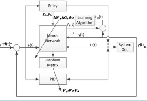
The proposed PID AutoTuning controller using radial basis neural network based on relay feedback approach (ATNNRF) control structure is shown in Figure 1. At the first phase of control, the relay feedback control mode is activated. The ultimate frequency and ultimate gain are obtained by the peak detection and calculation of the times between zero crossings of the control input level.
At the second phase of control, a neural network with back propagation algorithm is used to adjust the PID gains continuously.
2.2. Relay Feedback Control
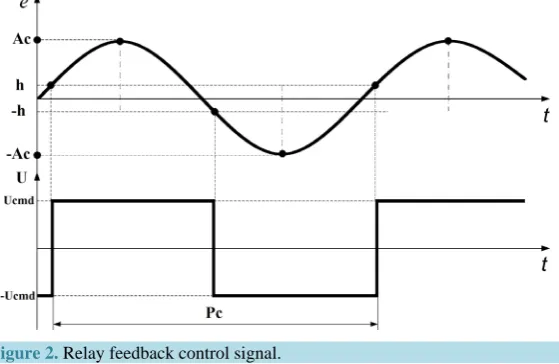
The ultimate gain and period of the system are determined by observing the ultimate frequency where the phase angle is -PI under a closed-loop relay feedback control.
[image:2.595.180.418.547.710.2]Relay feedback control signal are shown in Figure 2.
Figure 2. Relay feedback control signal.
The relay feedback control is carried out as following:
( )
( )
( )
if
if cmd
cmd
U e t h
U t
U e t h
≥
= − ≤
(1)
where U t
( )
is the control input of the system at current time; h is the hysterical level at which the control input switch to the opposite position; e t( )
is the position error of the control system at current time.Applying relay feedback control (1) to the motion system, we obtain a periodic signal with amplitude Ac and period Pc. In order to identify the ultimate gain from the relay feedback control, the describing function analysis is used.
Because the amplitude Ac and period Pc of the oscillation are measured from the relay feedback control, the ultimate gain Kc and ultimate frequency ωc can be obtained as following:
π 4
c c
cmd A K
U
= (2)
2π c
c P
ω = (3)
2.3. Radial Basis Function Neural Network
Since neural networks can approximate any continuous function over a compact set with high accuracy and fast learning capability, they have been recognized as a powerful tool for the applications of control system. It is proven that the standard 2-layer neural network consists of two layers of weights, threshold, a hidden layer and an output layer has sufficient generality for closed-loop control purpose.
In particular, the radial basis function neural network (RBFNN) is a feed-forward 2-layer neural network and demonstrates good control performance in the presence of unmodeled dynamics. The RBFNN can be considered as a local approximation model of control system. Moreover, the capability of online learning and rapid conver-gence of RBFNN makes it feasible in the application of control system.
The general RBFNN shown in Figure 3 can be presented in matrix form:
(
)
R R
Y =Wσ VX (4)
where W= wij and V = wjk are the weight vectors,
[
]
T 1, 2, , 1
R N
X = x x x is the input vector,
[
]
T1, 2, , 3
R N
Y = y y y is the output vector, and σ =
[
σ σ1, 2,,σN2]
T denotes the activation function vector.Figure 3. Radial basis function neural network.
(5)
where is the generalized basis function vector. In this paper, we use the radial basis func-tion with Gaussian form as following:
(6)
where is the node center of the i-th radial basis function, and is the width coeffi-cient.
2.4. The Incorporation of Relay Feedback to the Autotuning Controller Using Neural Network
The proposed PID autotuning controller based on neural network and relay feedback (ATNNRF) is designed by the following procedures:
-Firstly, the relay feedback control is carried out to analyze the system dynamic and calculate the ultimate gain and ultimate frequency of the control system by measuring the output amplitude and period.
-Secondly, a RBFNN with gradient descent algorithm is designed to approximate the system dynamic. In this step, the Jacobian matrix, denotes the sensitivity of control system output to the control input is obtained.
-Lastly, the ultimate gain and ultimate frequency calculated in the first step are incorporated with the Jacobian matrix to adjust the coefficients related to the PID control parameters.
Consequently, the PID gains are tuned automatically by the self-learning capability of neural network. It is proved from the simulations results that the proposed controller has the strong robustness, high adaptibility and high performance compared with other current researches and commercial products.
The design of proposed ATNNRF is described as below.
The conventional PID controller can be represented with the discrete form as followings:
(7)
Since the PID tuning parameters are uniform functions of ultimate gain and ultimate period as described in (2) and (3), they can be scaled for control system that has different time constant as followings:
p p c
K =ψ K (8)
c i i c K K P ψ
= (9)
d d c c
K =ψ K P (10)
where ψ ψ ψp, i, d are the scale factors that define the tuning rule.
The output of PID controller in (7) can be rewritten as the following discrete form:
( )
(
1)
( )
U k =U k− + ∆U k (11)
( )
p p( )
i i( )
d d( )
U k K e k K e k K e k
∆ = + + (12)
( ) ( ) (
1)
p
e k =e k −e k− (13)
( ) ( )
i
e k =e k (14)
( ) ( )
2(
1) (
2)
d
e k =e k − e k− +e k− (15)
( )
ref( ) ( )
e k =y k −y k (16)
where e k
( )
is the error of closed-loop control system.Applying the tuning rule from (8), (9), and (10), we obtain the update control output as follow:
( )
( )
c( )
( )
p c p i i d c c d
c K
U k K e k e k K P e k
P
ψ ψ ψ
∆ = + + (17)
Consider a RBFNN as in Figure 3. The input vector is presented as:
[
]
T( ) (
) (
)
T1, 2, 3 , 1 , 2
R
X = x x x = ∆ U k e k− e k− (18)
And the output of RBFNN is given by:
( )
R R
y =Wφ X (19)
Define the performance cost function of RBFNN as:
( )
1 2( )
2
R R
E k = e k (20)
( )
( )
( )
R R
e k =y k −y k (21)
where eR
( )
k is denoted as the approximation error.Apply the gradient descent method, we can obtain the updating parameters of weight vector, node centers and width coefficients of RBFNN as followings:
( )
(
1)
(
1) (
1)
i i R R i
w k =w k− +η e k− φ k− (22)
( )
( ) ( ) ( )
2(
( )
)
1
i ij
ij R i
i
x k o k
o k e k w k
k
σ −
∆ =
− (23)
( )
(
1)
(
1)
(
2)
ij ij R ij R ij ij
o k =o k− + ∆ +η o γ o k− −o k− (24)
( )
( ) ( ) ( )
( )
( )
( )
2
3
i
i R i i
i
X k O k
k e k w k k
k
σ φ
σ −
∆ = (25)
( )
(
1)
(
1)
(
2)
i k i k R i R i k i k
where ηR is the learning rate of RBFNN, and γR is the momentum gene. The Jacobian matrix for the model identification is obtained as follows:
( )
y k( )
( )
J k
U k
∂ =
∂ (27)
Gradient descent is an iterative method that is given an initial point, and follows the negative of the gradient in order to move the point toward a desired local minimum.
In this paper, we assume that the approximation error in (21) converges to zero by gradient descent algorithm, then (27) can be rewrite as follows:
( )
( )
( )
2( ) ( ) ( )
( )
( )
1 1 2 1 N R i i i i i
y k o k U k
J k w k k
U k = φ σ k
∂ − ∆
= =
∂
∑
(28)The PID control parameters can be obtained through the calculation of scale factor as described as followings: Define the cost function of system as following:
( )
1 2( )
2
E k = e k (29)
According to the gradient descent method, the scale factors can be updated by the following rules:
( )
p R R
p p
E E y U
k
y U
ψ η η
ψ ψ
∂ ∂ ∂ ∂
∆ = − = −
∂ ∂ ∂ ∂ (30)
( )
i R R
i i
E E y U
k
y U
ψ η η
ψ ψ
∂ ∂ ∂ ∂
∆ = − = −
∂ ∂ ∂ ∂ (31)
( )
d R R
d d
E E y U
k
y U
ψ η η
ψ ψ
∂ ∂ ∂ ∂
∆ = − = −
∂ ∂ ∂ ∂ (32)
From (17) and (27), we can obtain:
( )
( ) ( )
( )
p k Re k J k K ec p k
ψ η
∆ = (33)
( )
( ) ( )
c( )
i R i
c K
k e k J k e k
P
ψ η
∆ = (34)
( )
( ) ( )
( )
d k Re k J k K P ec c d k
ψ η
∆ = (35)
Consequently, the PID control parameters can be obtained and the system is automatically tuned.
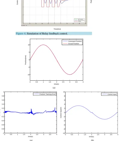
3. Simulation Results
The simulation is carried out by Matlab/Simulink with required inputs to achieve desired level of control and results.
The simulation of relay feedback control is shown in Figure 4. The results of ultimate gain and ultimate fre-quency are figured out by measuring the output amplitude and period as follows: Ac=0.5 mm; Ucmd =1 V;
90 ms c
P = .
Therefore, the ultimate gain and ultimate frequency are:
0.39 c
K = ; ω =c 69.7 Hz.
The learning rate and momentum gene of neural network are selected as followings: η =R 0.0001; 0.0001
R
γ = .
Number of hidden neural is set as N2 =10.
Sine wave with frequency of 0.25 Hz is used as reference profile for motion control system. The disturbance is a random noise signal.
control system has tracked the desired sine wave position, and the position tracking error in Figure 5(b) proves the robustness and high tracking ability of the proposed controller.
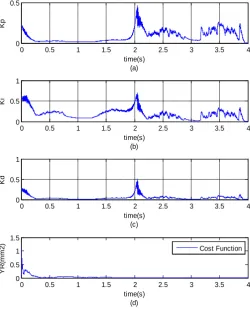
[image:7.595.174.423.131.318.2]The simulated PID autotuning parameters and cost function of ATNNRF at 0.25 Hz are shown in Figure 6.
Figure 4. Simulation of Relay feedback control.
(a)
(a) (b)
Figure 5.Simulated response of ATNNRF control system at 0.25 Hz. (a) Position tracking; (b) Error; (c) Control input.
Control Input
(V
)
Time(ms)
Pos
(mm
)
0 0.5 1 1.5 2 2.5 3 3.5 4
-10 -5 0 5 10
time(s)
P
os
it
ion(
m
m
)
Command Position Actual Position
0 0.5 1 1.5 2 2.5 3 3.5 4
-1 -0.8 -0.6 -0.4 -0.2 0 0.2 0.4 0.6 0.8 1
time(s)
E
rro
r(m
m
)
Position Tracking Error
0 0.5 1 1.5 2 2.5 3 3.5 4
-10 -8 -6 -4 -2 0 2 4 6 8 10
time(s)
C
ont
rol
I
nput
(V
)
[image:7.595.117.515.219.690.2]Figure 6.Simulated PID autotuning parameters of ATNNRF control system at 0.25 Hz. (a) Kp Gain; (b) Ki Gain; (c) Kd Gain; (d) Cost function of RBFNN.
The fast convergence of the simulated cost function ER of ATNNRF has proven the effectiveness of the pro-posed controller scheme.
4. Conclusion
This paper successfully demonstrates the application of an autotuning of PID controller based on neural network and relay feedback approach. First, the principle of relay feedback control is introduced to find the ultimate gain and ultimate frequency for the initial conditions of the neural network controller. Then, the results of relay feedback control are incorporated with the neural network to adjust the PID gains online through the gradient descent algorithm. An embedded motion control board with high performance DSP has been developed to im-plement the proposed control algorithms. The simulation results have proven the robustness and high tracking ability of the proposed controller.
Acknowledgements
This work was supported by Dong-Eui University Foundation Grant (grant number 2014AA441).
References
[1] Desborough, L. and Miller, R. (2002) Increasing Customer Value of Industrial Control Performance Monitoring— Honeywell Experience. In: Rawlings, J.B., Ogunnaike, B.A. and Eaton, J.W., Eds., 6th International Conference on Chemical Process Control, AIChE Symp., Series 326, AIChE, New York, 172-192.
[2] Levy, S., Korotkin, S., Hadad, K., Ellenbogen, A., Arad, M. and Kadmon, Y. (2012) PID Autotuning Using Relay Feedback. IEEE 27th Convention of Electrical & Electronics Engineers in Israel (IEEEI),Eilat, 14-17 November 2012, 1-4.
0 0.5 1 1.5 2 2.5 3 3.5 4
0 0.5
time(s) (a)
Kp
0 0.5 1 1.5 2 2.5 3 3.5 4
0 0.5 1
time(s) (b)
Ki
0 0.5 1 1.5 2 2.5 3 3.5 4
0 0.5 1
time(s) (c)
Kd
0 0.5 1 1.5 2 2.5 3 3.5 4
0 0.5 1 1.5
time(s) (d)
Y
R
(mm2
)
[image:8.595.173.424.87.398.2][3] Tang, W., Wang, Z.F., Zhang, J.G. and Wang, M.X. (2010) A Relay Feedback Based Autotuning PID Controller and Its Application to Pulp Consistency Control. 29th Chinese Control Conference (CCC),Beijing, 29-31 July 2010, 3406- 3410.
[4] Tang, W., Shi, S.J. and Wang, M.X. (2003) Relay Feedback Based Autotuning PID Control of Paper Basis Weight in Paper Making Process. Journal ofSystems Engineering and Electronics, 14, 63-69.
[5] Majhi, S. and Atherton, D.P. (1999) Autotuning and Controller Design for Processes with Small Time Delays. IEE Proceedings of Control Theory and Applications, 146, 415-425.
[6] Zhu, A.-D., Xing, J.-G. and Zhao, W.-M. (2010) An Autotuning PID Control Algorithm for Sensorless DC Motors. In-ternational Conference on Electrical and Control Engineering (ICECE), Wuhan, 25-27 June 2010, 369-372.
[7] Vrana, S. and Sulc, B. (2011) PID Controller Autotuning Based on Nonlinear Tuning Rules.12th International Car-pathian Control Conference (ICCC),Velke Karlovice, 25-28 May 2011, 443-446.
[8] Alavi, S.M.S., Akbarzadeh, A. and Farughian, A. (2011) Auto-Tuning Smith-Predictive Control of Three-Tanks Sys-tem Based on Model Reference Adaptive SysSys-tem. 2nd International Conference onControl, Instrumentation and Au-tomation (ICCIA), Shiraz, 27-29 December 2011, 711-714.
[9] Toledo, C.F.M., Lima, J.M.G. and da Silva Arantes, M. (2012) A Multi-Population Genetic Algorithm Approach for PID Controller Auto-Tuning. IEEE 17th Conference onEmerging Technologies & Factory Automation (ETFA), Kra-kow, 17-21 September 2012, 1-8.
[10] Alavije, H.S. and Akhbari, M. (2013) Auto-Tuning PID Controller for Low Cost Fault Tolerant Motor Drive of Electric Vehicle. 4thPower Electronics, Drive Systems and Technologies Conference (PEDSTC),Tehran, 13-14 February 2013, 38-43.
[11] Wu, Y.-J., Jung, Y.-G. and Lim, Y.-C. (2012) Auto-Tuning Fuzzy PD Control Scheme for Output Voltage Control of Three-Phase Z-Source Inverter. IEEE International Symposium on Industrial Electronics (ISIE),Hangzhou, 28-31 May 2012, 222-227.
[12] Blondin, M.-J. and Sicard, P. (2013)PID Controllers and Anti-Windup Systems Tuning Using Ant Colony Optimiza-tion. 15th European Conference onPower Electronics and Applications (EPE),Lille, 2-6 September 2013, 1-10.
[13] Crowe, J. and Johnson, M.A. (1999) A New Nonparametric Identification Procedure for Online Controller Tuning. Proceedings of the 1999 American Control Conference, 5, 3337-3341.