Survey on TCP Friendly Congestion Control for
Unicast and Multicast Traffic
Nikhil Singhal
Department of Computer Engg. National Institute of Technology Kurukshetra
India
R.M. Sharma
Department of Computer Engg.
National Institute of Technology Kurukshetra, India
ABSTRACT
Increasing popularity of real time traffic application has lead to increase in non TCP traffic over the internet. These non TCP applications does not provide adequate congestion control compared to TCP application sharing same network thus available bandwidth is shared unfairly and may lead to stall of TCP traffic. M any TCP-Friendly protocols have been proposed that can share the available bandwidth with TCP traffic fairly and in such a way that Non TCP flow have same throughput as TCP one when are under same network conditions. These schemes have different characteristic and are best suited for different network conditions. In this paper we discuss various available TCP friendly schemes and discuss their features.
Keywords
Congestion control, M ulticast, Unicast, TCP-Friendly.
1.
INTRODUCTION
TCP is a connection oriented unicast protocol that provides the reliable data transfer and also supports flow and congestion control. There are various schemes for congestion control for TCP but over internet non TCP application are also present which do not have congestion control mechanism so these application do not share bandwidth fairly with TCP based application. As the traffic from such TCP unfriendly application like IP telephony, video conferencing, audio conv ersations, online movies is increasing there is need to solve this unfairness. TCP flow adjust their flow rate once congestion is detected but non TCP flow continue to send at same uncontrolled rate since these have strict latency requirements than reliable delivery causing unfairness and in worse case leading to congestion collapse.
By TCP Friendly we mean scheme that uses bandwidth equivalent to TCP that is flow is TCP compatible [5]. Large number of TCP friendly schemes has been proposed to solve this unfairness problem [1, 2, 7-9, 11, 12, 18, 21, 26]. Case of multicast is even worse as in this case different members of group may have different characteristics (link bandwidth available, processing capability and QoS requirements) and also congestion level of receiver link can also be different. If a sender adjusts its sending rate for every loss indication by receiver then its transmission rate will be completely throttled [13] so there is a need to find a way to select most suitable receiver such that most congested path is selected and network bandwidth is utilized to maximum possible.
In this paper we discuss different proposed TCP friendly congestion control schemes. This paper is divided into following sections in section 2 we will provide the classification criteria for the available schemes in section 3 we will discuss available unicast schemes in section 4 we will discuss single rate multicast
schemes, in section 5 we will discuss multi-rate schemes and conclude in section 6.
2.
CLASSIFICATION CRITERIA
TCP friendly congestion control schemes can be classified based of the following criteria.
2.1
End to End and Network supported
TCP friendly schemes can be classified on basis of where the congestion control mechanism is implemented. End to End as the name specifics handles the congestion control without relying on the network components (like routers) here the sender adjust the data flow rate based on the feedback provided by the receiver. Receiver supports congestion control by sending its feedback and also decides what layers to join in layered approach for multi cast traffic as we will see later receiver can decide whether to join or leave layers depending upon its congestion status. End to End schemes are easy to implement compared to network supported schemes. Demerit of such approach is that greedy non TCP applications can get unfair share of bandwidth competing with TCP flows, fair sharing of bandwidth can be made possible by implementing congestion control that is assisted by network. Routers can detect congestion and send feedback to sender and sender can adjust its sending rate. Compared to end to end where sender keep pumping data at same rate till receiver’s feedback is received network assisted congestion control can send indicator packets to its parent thus control starts before actual steps taken by senders. Routers can also drop the packets from non TCP flow if it discovers that flow is not showing TCP friendly behavior. Network based approach are hard to implement compared to end to end based schemes as they may require changes in the internet infrastructure that may be not feasible.2.2
Unicast and Multicast
available bandwidth so selecting the best possible congestion representative such that congestion problem is controlled and network resource are utilized to best possible is a prime need.
2.3
Single rate Vs Multi-rate
This classification is valid only for multicast traffic. In single rate a sender send data at same rate to all the receivers this approach limits the maximum transfer rate for all the receiver since all receiver will get data at same rate that is limited by the rate of bottleneck receiver, whereas in multi-rate a sender sends data at multiple rates. This scheme is best for the receivers with heterogeneous receiving rate and thus provides better scalability but these schemes are relatively complex and require frequent feedback. In M ulti-rate schemes the source maintains several layers each having different transmission rates, receivers depending upon their network bandwidth and congestion status can subscribe to different subset of layers. Each of these layers uses a separate multicast group address so each receiver depending on its bottleneck bandwidth can join multiple groups more the number of groups joined better is transmission rate and quality. Care has to be taken while leaving or joining a multicast group for most effective congestion control.
2.4
Window Vs Rate based
A congestion control scheme can adapt its load either using congestion window or varying their transmission rate. Window based protocol maintains congestion window consisting of slots at sender or receiver to provide TCP friendliness. Like TCP transmission consumes one slot of window and on receiving acknowledgement of packet received one slot is freed. In absence of any free slot no transmission is allowed. In window based scheme congestion window size is increased if no congestion is detected and reduced when packet loss occurs.
Rate based protocol on other hand adjust its transmission rate dynamically based on feedback provided by network. In these schemes sender adjust its sending rate such that transmission rate is TCP friendly. In order to send packet sender do not wait for acknowledgement and can send multiple packet at same time.
Window based approaches reacts quickly reducing number of packets to be transferred to packet loss event, rate based schemes on other hand has to wait for feedback before appropriate action can be taken thus continue sending at same rate.
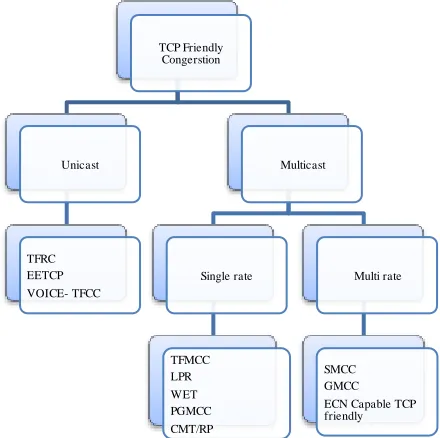
Figure 1 shows the above described classification. In next session we will discuss various protocols based on these classifications.
3.
UNICAST SCHEMES
3.1
TFRC
TCP-Friendly Rate Control [14] is a single rate unicast equation based congestion control scheme. TFRC functionalities are located at the receivers. In this scheme sender calculates its sending rate that is TCP-Friendly. In order to calculate sending rate sender uses TCP throughput equation (1) which is a function of loss event rate, RTT and segment size.
[image:2.612.329.549.75.294.2](1)
Fig 1: Classification of TCP Friendly S chemes
Where:
s is segment size in bytes, RTT is round trip time in seconds,
RTO is TCP retransmission timeout in seconds, p is loss event rate,
b is maximum number of packets acknowledged by single TCP ack.
For b=1 equation (1) can be rewritten as:
(2)
Receiver measure loss event rate and send this information back to sender. To calculate loss event rate receiver needs to find loss events where loss event is one or more packets lost or marked in an RTT. Timestamp value along with RTT is used by receiver to determine losses belong to same loss event or not. In order to smooth loss event rate change TFRC uses average loss interval by using filter that weight the ‘n’ most recent loss event intervals. The segment size is normally known to an application. To measure RTT sender make use of timestamp and sequence number, receiver echoes the timestamp to enable sender to estimate the RTT. RTT is also used to determine when to send feedback packets.
Loss event rate and RTT is then fed to TCP throughput equation at senders end to calculate the TCP friendly rate. Sender then adjusts its sending rate according to this calculated rate. TFRC uses slow-start mechanism to quickly approach fair bandwidth share at the start of the session. Slow-start phase is terminated with the first loss event. There is a trade-off between measuring accurate loss event rate and responding rapidly to changes in the available bandwidth [1].
TFRC has low variation in throughput and thus suitable for streaming media applications where smooth sending rate is of importance. Penalty of smoothness is reduced responsiveness to change in available bandwidth. In order to maintain a smooth
TCP Friendly Congerstion
Unicast
TFRC EETCP VOICE- TFCC
Multicast
Single rate
TFMCC LPR WET PGMCC CMT/RP
Multi rate
sending rate on a longer timescale, an ATF (Average TCP Friendliness) protocol must have a lower average sending rate [20]. TFRC response to congestion by varying sending rate of packets per second keeping packet size same so not suitable for applications that require fixed interval and vary packet size.
RFC 5348 added several changes to RFC 3448[16] like:
Provides support to send a burst of packets if data arrives from the application in a burst after a data-limited period.
Higher initial sending rates.
Use of coarse-grained timestamp instead of fine-grained timestamp using milliseconds.
Various improvements over TFRC are proposed in [23, 24, 25]. In [25] authors try to make TFRC reliable by using selective retransmission concept into TFRC. Retransmission is done only when no congestion exists. [23] Show the effect of increasing number of feedback on TFRC. TFRC throughput is guided by TCP throughput equation with loss rate and RTT as key parameters, [23] show that when feedback frequency is greater than one per RTT lead to decrease drop rate since RTT value is increased and measured more accurately in steady state. ETFRC [24] shows that having feedback frequency value four per RTT is optimal for best visual quality of video sequences transmit ted over TFRC. ETFRC produces higher Peak signal to noise ratio (PSNR).
3.2
VOICE-TFCC
Voice TFCC couples RTP voice flow multiplexing with and TCP-friendly congestion control mechanism [8] for VoIP flows. This protocol is applied to many VolP flows transmitted between two VolP gateways but can also be used by a single VolP flow. There is a tradeoff between size of the payload and latency, since as size of payload decreases demand of bandwidth per channel band increases and thus decrease transmission efficiency and overall latency of each call decreases as smaller is payload size lesser is time to buffer voice samples. Voice-TFCC has techniques for controlling both packet rate and codec rate of VoIP flows to adapt the control traffic to the network congestion state.
In this scheme receiver calculates the loss rate for an interval and sends it feedback to sender, which adjust its sending rate by calculating RTT and feeding both loss rate and RTT to TCP-Friendly equation (2) to get TCP TCP-Friendly rate, sender then adjust number of packets to be multiplexed into one UDP packet so that multiplexed packet have throughput that matches one calculated by TCP-friendly equation. The total number of voice packets that are to be multiplexed should be obtained by considering tradeoffs between delay and bandwidth efficiency improvements. Larger are number of p acket to be multiplexed lesser is control overhead but more is delay since multiplexer now has to wait to get sufficient packet to multiplex.
When maximum number of packet that can be multiplexed reaches its limit then this scheme reaches its second phase which consists of changing the codec rate. The codec rate to be is selected by the gateway sender is determined by equation.
Voice-TFCC multiplexes packets from different sources hence adds synchronization delay needed to multiplex packet from different source so larger the value of multiplexing better is bandwidth utilization but delay will also increase.
3.3
EETCP
ECN based and Enhanced fairness TCP friendly congestion control [9] is congestion control mechanism for steaming multimedia combining end to end control with network support, EETCP end to end control is similar to TFRC as it also make use of TCP friendly response function (1) to adjust sender sending rate that is TCP friendly for which it calculates RTT, RTO and packet loss event rate as in TFRC.
In EETCP network itself participate in controlling its own resource utilization by making use of ECN algorithm [10] idea is to mark rather than drop packets at the router. EETCP further make use of improved RED [6] random early detection which drops packet randomly as a function of the average queue size. RED Is not completely fair to the flows having variable packet size since it drop packet of all size with uniform drop probability which is disadvantageous for shorter packet.
EETCP uses ERED algorithm which have different drop probability for different size packet. Idea is to have higher drop probability of packets of large size compared to packets of smaller size. Where packet drop probability is given by:
(3)
Where B is packet size, M is maximum packet size and pb is
packet mark probability.
For which it make use of count parameter which is number of arriving unmarked packets that have reached since last market packet. Count given by:
(4)
EETCC flows response swiftly to congestion, share the bandwidth of the bottleneck link with the TCP flows, and have the good TCP-friendly.
3.4
CMT/RP-SCTP
Concurrent multipath transfer (CMT) [26] exploits the existence of multiple paths at endpoints to increase throughput. The issue with multiple paths is handling congestion control for each path independently does not provide fairness against other non-CMT flows. This approach combines CMT with M odified Resource Pooling (RP) [28] to provide fairness still achieving throughput improvement.
SCTP (Stream Control Transmission Protocol) [27] is a connection-oriented, unicast transport protocol with CMT option, providing reliable transport. SCTP connection is called association, currently SCTP uses only one path in direction to transmit data chunks on one time this path is called primary path which may be changes if needed, all other paths are used only for retransmission. CMT-SCTP utilizes all paths of SCTP each path have its own congestion window and slow start threshold, such that till a path has sufficient space in its congestion window transmission of data can take place over that path. Problem with CMT-SCTP is that though it share equal bandwidth in a path for saturated TCP and SCTP but when multiple path (n) of SCTP share a bottleneck link with TCP, SCTP gets n time more share then TCP.
bottleneck link so drop occurring at one path must be consider at all other paths while selecting their transmission rate. CMT/RP-SCTP makes the following changes to handle unfairness:
Let and
Where C is overall congestion window and S is overall slow start threshold.
Then on fast retransmission on path P:
Where sp and cp are slow start threshold and congestion window respectively for path P. Author incorporate the possibility of shared bottlenecks by trying to halve the overall congestion window on the lossy path.
For time-based retransmission on path P:
MTUP is maximum transmission unit for path P.
For α acknowledged bytes in a fully –utilized congestion window during slow start phase:
Assuming the slow start threshold to be a useful metric for the capacity of a path and only increasing the congestion window by the fraction of sP and S, i.e. the capacity share of path P.
For each fully acknowledged window in congestion avoidance phase:
Simulation results show that CM T/RP using above modified equation achieves improvement over standard SCTP while remaining fair to concurrent flows so that non CMT flow can have more bandwidth over shared link. Once congestion is detected, in case of two disjoint paths of which one having congestion, CMT/RP based flow concentrate more on path with no congestion leaving more share of bottleneck path to non-CMT based traffic, while if two paths share same bottleneck link then CMT/RP occupies 50% of its share with competing non CM T flow.
4.
MULTICAST SINGLE RATE SCHEMES
4.1
TFMCC
TCP-Friendly M ulticast Congestion Control [15] is a single rate multicast congestion control scheme that extends the unicast TFRC mechanism for multicast traffic. TFM CC supports both Any-Source and Source-Specific M ulticast model. Like TFRC, TFM CC functionalities are located at the receivers. In this scheme each receiver calculates it’s desired receive rate that is TCP-Friendly and sends it to sender as a feedback packet. In order to calculate desired rate receiver uses TCP throughput equation (5)
for which receiver needs to measure loss event rate and its RTT to the sender.
(5)
To calculate loss event rate receiver needs to find loss events (loss of one or more packets in a RTT) separated by the loss interval. In order to smooth loss event rate change TFM CC uses average loss interval by using filter that weight the ‘n’ most recent loss event intervals.
Value of ‘n’ determines the speed in responding to changes in the level of congestion. To measure RTT receiver send a timestamp with receiver report which is echoed by the sender.
In order to prevent feedback implosion problem, TFM CC makes use of feedback suppression mechanism by which only a subset of receivers are allowed to send feedback. From the feedback obtained sender select the receiver with lowest rate as CLR (current limiting receiver). Sending rate increases or decreases as per feedback obtained from the receivers. TFM CC uses slow-start mechanism to quickly approach fair bandwidth share at the start of the session. This rate increase is limited by the minimum of the rates in receivers report.
Selected CLR have to send feedback report once per RTT where as non CLR sends feedback on expiration of feedback timer.
Like TFRC, TFM CC has low variation in throughput and thus suitable for streaming media applications. Penalty of smoothness is reduced responsiveness to change in available bandwidth. TFM CC may be inaccurate to estimate of loss event rate in case receiver receives few packets RTT so not suitable to use along with TCP for bottleneck link with below 30Kbps speed also TFM CC response to congestion by varying sending rate of packets per second keeping packet size same so not suitable for applications that require fixed interval and vary packet size.
4.2
LPR
Linear Proportional response [7] is a single rate multicast congestion control scheme that is based on LIF (Loss Indication Filter). LIF is used to filter out loss indications received from different receivers.LIF is needed as if no filter is applied and multicast session reduces its rate for all loss indications then transmission rate will be completely throttled. [13]. Different other filter based approaches are available [4, 7] which differ in their mechanism how they suppress loss indication by various receivers. LIF and rate adjustment algorithm are two important blocks of LPR scheme. Loss Indications from receiver are first passed from LIF filter which suppress losses from all but one receiver know as congestion indicator (CS). This selected CS is then fed as input to rate adjustment algorithm which adjust its sending rate as per selected receiver.
LPR passes loss indication with the probability of αi where
α
i=X
i/
, i= 1,2,….N.
Where
Xi is the number of losses for receiver,
N is the receivers for a given multicast session.
a CS. As we can see that probability of passing through filter increases as the number of loss for a receiver increases.
Once the CS is selected sender adjust it sending rate using rate adjustment algorithm such that at a given time if r represent current transmission rate of source then value of r is adjusted in response to CSs in following manner.
On receiving CS sender reduces its sending rate given by r = r-r/C.
In absence of any CS for time S sender increase its sending rate as r =r+1.
Where C and S are adjustable parameters.
4.3
PGMCC
PGM CC (Pragmatic General M ulticast Congestion Control) [11] is a single rate multicast congestion control scheme and is suitable for both reliable and non reliable traffic. It works as follows at the beginning all the receivers calculates their loss rate and send this information to the sender in NAKS and ACKS along with other information like receiver id, higher known sequence number, NAKs and ACKs carry sufficient information (loss rate) for sender to calculate the throughput using this loss rate and calculate RTT. Sender calculates the most effected receiver i by comparing receiver’s throughput T(Xi) in set {R} of receivers,
such that:
Now this receiver is chosen as the acker (representative) and sender adjust its sending rate based on this receiver for a given session.
Sender mimics window based congestion control of TCP between sender and selected acker where sender sends new packets on receiving ack for the previous packet, once the throughput of current acker exceeds throughput from any other receiver acker is switched. PGM CC can be used for both reliable and non reliable transfer.
This scheme does not make use of receiver based RTT measurement, here sender calculates RTT in terms of packets. Sender simply computes the difference between the most recent sequence number sent and the highest sequence number information value coming from the receiver. Compared to other sender based RTT measurement this scheme does not need to send timestamps or rely on the timer resolution at receiver. For calculating loss rate receiver interprets packet arrival pattern as discrete signal considering 1 for packet loss else 0 and passes this signal through discrete time linear filter.
PGM CC also provide support to make use of network based feedback like routers can be used to aggregat e the NACK to remove redundant loss by multiple receivers but at the same time PGM CC can work even without any network support. PGMCC provides fairness in both intra protocols as well as inter protocol case. When 2 receiver have similar throughput and can act as a acker, frequent switches are possible PGMCC handle this by introducing a constant C which act as bias in favor of current acker and acker only switch if throughput of current acker is less than C time the throughput of new acker where value of c lies between 0 and 1.
Acker selection process of the PGM CC is approximate and based on assumption that might not be always true. Both RTT and p
(loss rate) are calculated with uncertainties for this reason one cannot interpret switching of acker as congestion indicator. One of the problem of PGM CC is selection of wrong acker under some network condition also aggregation of NAKs can also leads to wrong selection of acker since a receiver report with worst rate can be suppressed by router.
4.4
Slack Term
As discussed earlier TEAR [17] and TFRC [14] make use of Average loss interval to provide smoothness in transmission rate for this purpose these scheme uses n previous loss event rates and provides weights over them but the problem is what value of n should be taken and how to set appropriate value of weights.
Slack Term [18] first calculates the transmission rate by making use of TEAR or TFRC, slack term limits the variation in this calculated rate and provides smooth sending rate by making use of three parameters α, β and C keeping the TCP friendliness, α and β are used to provide necessary variation in sending rates and C is used to accumulate the difference between original sending rate (by TEAR and TFRC) and by slack term.
Packets that are to be transmitted as per TEAR or TFRC for time interval Ti-1 and Ti is given by:
Where Ti is time of ith rate change of TCP friendly flow,
denotes sending rate calculated in TEAR or TFRC.
And the actual number of packets that are transmitted is given by:
Where denotes sending rate for slack term.
C which shows packets to be compensated in future can be updated from A and E by:
Ci= Ci-1+Ei-1 –Ai-1
That is:
If Ci is positive then we can say that flow has obtained less
bandwidth than it should get and we increase the current sending slack term rate as
Else if Ci is a negative than flow has obtained more bandwidth
than it should get and thus we decrease the current slack term rate given as:
In case if value of Ci is zero then sending rate is remained
unchanged.
5.
MULTICAST MULTI-RATE SCHEMES
Since source sends data at single rate which is based on the slowest receiver present in multicast group, single rate have disadvantage that fast receiver will not utilize available bandwidth. This disadvantage is taken care by multi rate schemes where source sends data at different transmission rate by using layered approach here source sends data at different rates to different layers representing a multicast group, a receiver can join any multicast group depending upon its available bandwidth and congestion status receiver can join multiple layers to satisfy its requirements. Based on scheme used a receiver can join and leave a group anytime, different multi rate schemes have been proposed (RLC [19], GM CC [12], SM CC [2]). Receiver has to join a group to increase its transfer rate and leave a group to decrease its transfer rate.5.1
SMCC and GMCC
Smooth multi-rate multicast congestion control [2] is a multiple rate equation based multicast congestion control scheme. SM CC combines the advantages of TFM CC smooth rate control and TCP friendliness to multiple rates scalability and flexibility.
In this approach receiver subscribes to set of cumulative layers, receiver is active participant in its uppermost layer and passive in other layers. For each layer transfer rate is regulated by CLR (current limiting receiver) of that layer which is one of the active participants in that layer. Each receiver calculates its throughput if this throughput is above maximum sending rate of its current subscribed layer receiver attempt to join higher layer using additive increase method, in case of lower throughput then minimum of this layer it drops to lower layer.
Drawback of SM CC is that it fixes maximum sending rates for each layer as well as the number of layers. Thus if more receiver falling to lowest layer possible SM CC cannot make new layer with low sending rate making all receiver to receive data at single rate, also redundancy of higher layer if more receiver joins highest layer is also not solved, this requirement makes SM CC not capable of accommodating receivers with variant bandwidth circumstances.
GM CC (Generalized M ulticast Congestion Control) [12] is a multi rate multicast congestion control scheme that provides multi rate features at low complexity GMCC solves various problem of SM CC while having merits of SM CC. In this approach the function of source and receivers is divided into intra layer and inter layer categories. GM CC use single rate M CC to manage intra layer activities (rate adaptation and congestion representative selection). Layer join and leave operations are done at receivers, unsatisfied receivers can join new layer if their congestion is significantly less than that of CR of their highest layer, if a receiver is selected as CR of more than one layer then it unsubscribe from its highest layer.
Unlike other multi-rate schemes GM CC allows variation in number of layers and varying the transfer rate within the layer is also possible. When a source identify that no receiver is present at a layer it deactivates that layer on other hand when a receiver join a layer which did not have any receiver ear lier activation of that layer take place.
Advantages of GM CC over other schemes are sending rate of each layer can be adjusted according to need, variation in number of layer used is also possible thus controlling the throughput of multicast session, also there is no redundancy of layers thus avoiding unnecessary exchange of control information.
Author has proposed TAF (throughput attenuation factor- highly sensitive statistical measurement of congestion at receiver side) and PIBS (probabilistic interlayer bandwidth switching to discover inter layer rate allocation sub-optimally) techniques to solve inter layer management problems.
For a given layer source select the most congested receiver as a CR for this layer and uses the feedback provided by this CR for rate adaptation, CR on detection of packet loss send feedback packet to the source as Congestion indicator (CI). While selecting or updating CR source compare the TAF of different receiver as provided in CIs.
5.2
ECN-capable
TCP-friendly
Layered
Multicast Multimedia Delivery
ECN-capable TCP-friendly layered multicast multimedia delivery [21] combines receiver-driven layered architecture (receiver deciding to leave or join a layer to decrease or increase its transmission rate) with explicit congestion notificat ion capable RTP protocol [30] and the TCP-friendly multicast scheme. Unlike other known TCP-friendly protocols which use TCP throughput equation, this scheme assures TCP-friendliness by emulation, here decisions about adapting transmission rate, are taken based on TCP emulation.
In absence of any congestion TCP increases its congestion window size (congestion window is linearly increased by 1 after RTT) based on this fact this scheme emulate TCP by increasing BW variable representing TCP throughput if TCP congestion window is increased by 1 then BW is given by:
Thus:
Based on the increased value of BW a receiver can decide to join more layers if required rate exceeds rate of currently joined layers.
TCP reacts to congestion by decreasing its congestion window to half, this behaviour is emulated by given scheme by decreasing the BW variable:
Likewise if calculated BW is less than bit rates of currently joined layers by a receiver, receiver will leave layers according to BW variable.
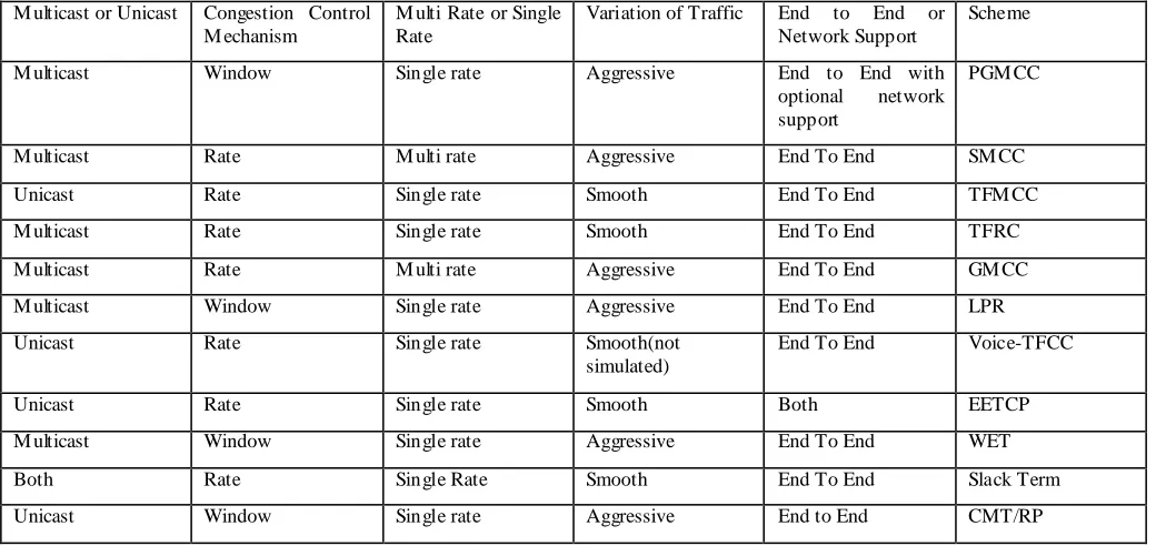
Table 1. Characteristics of different congestion control schemes
M ulticast or Unicast Congestion Control M echanism
M ulti Rate or Single Rate
Variation of Traffic End to End or Network Support
Scheme
M ulticast Window Single rate Aggressive End to End with
optional network support
PGM CC
M ulticast Rate M ulti rate Aggressive End To End SM CC
Unicast Rate Single rate Smooth End To End TFM CC
M ulticast Rate Single rate Smooth End To End TFRC
M ulticast Rate M ulti rate Aggressive End To End GM CC
M ulticast Window Single rate Aggressive End To End LPR
Unicast Rate Single rate Smooth(not
simulated)
End To End Voice-TFCC
Unicast Rate Single rate Smooth Both EETCP
M ulticast Window Single rate Aggressive End To End WET
Both Rate Single Rate Smooth End To End Slack Term
Unicast Window Single rate Aggressive End to End CMT/RP
6.
CONCLUSION/FUTURE WORK
In this paper we have discussed various TCP friendly congestion control mechanism. Table 1 shows different characteristics of discussed schemes. Over internet non-TCP flows competes with TCP one and thus making it necessary for TCP friendliness. We have covered schemes for both unicast and multicast traffic, we have also survey the different types of congestion control mechanism applying congestion based on different traffic need single rate for uniform sending rate and multi rate schemes for multiple sending rates.
We have also discussed what scheme to be used under what condition discussing their pros and cons. Also provide classification of these schemes based on their characteristic like sending rate, network or end to end and unicast or multicast. Overall table of these schemes have been provided for easy understanding of these schemes.
Various schemes have been proposed in these recent years and more work is still in progress. Though all scheme have some advantage and disadvantages increased fairness and improvement comes with overhead price to pay different scheme try to manage this increased overhead my transferring processing overhead at different ends like receiver, sender and on network. There is a need of common standard approach. Also most of these schemes are simulated over simulation tool available without been valid test over actual environment which might give different result. Also there is a need of some performance comparison of these schemes using some standard test conditions to compare t heir advantages and disadvantage more validly. M ost of these schemes use TCP response function to calculates rate that is TCP friendly for this purpose these scheme calculates parameters required for this equation more vaguely with various non real assumpt ions which results in less precise sending rate.
7.
ACKNOWLEDGMENTS
We would like to thanks anonymous reviewers for their invaluable comments and feedback on the paper.
8.
REFERENCE
[1] Floyd, S., Handley, M ., Padhye, J., and Widemer, J. 2000. Equation-based Congestion Control for Unicast Applications. Proceedings of ACM SIGCOMM (Aug. 2000), 43–56.
[2] Kwon, G.I. and Byers, J. 2003. Smooth multirate multicast congestion control. In Proceedings of IEEE INFOCOM (April 2003), 1022-1032.
[3] Widmer, J., Denda, R., and M auve, M . 2001. A survey on TCP- Friendly Congestion Control. Network, IEEE (M ay 2001), 28-37.
[4] Wang, H.A. and Schwartz, M . 1998. Achieving Bounded Fairness for M ulticast and TCP traffic in the Internet, Proceedings of ACM SIGCOMM (Oct 1998).
[5] Braden, B., Clark, D., Crowcroft, J., Davie, B., Deering, S., Estrin, D., Floyd, S., Jacobson, V., M inshall, G., Partridge, C., Peterson, L., Ramakrishnan, K., Shenker, S., Wroclawski, J., and Zhang. L. 1998. Recommendations on Queue M anagement and Congestion Avoidance in the Internet. RFC 2309 (Informational, Apr. 1998).
[6] Floyd, S. and Jacson, V. 1993. Random Early Detection gateways for congestion avoidance. IEEE/ACM Trans. on Networking, 397-413.
[8] Trad, A. and Afifi, H. 2008. Voice-TFCC: a TCP-Friendly Congestion Control scheme for VoIP flows. IEEE PIM RC (Sept. 2008), 1-5.
[9] Xiao, P.P. and Tian, Y.T. 2007. A TCP-Friendly Congestion Control mechanism combined with the routers. IEEE ICM LC (Hong Kong, Aug 2007), 3223-3228.
[10]Ahmed, U and Salim, J. 2000. Performance Evaluation of Explicit Congestion Notification (ECN) in IP Networks. RFC 2884.
[11]Rizzo, L. 2000. PGM CC: A TCP-friendly single-rate multicast congestion control scheme. In Proceedings of ACM SIGCOMM (Oct 2000).
[12]Jiang, L., M urat, Y., Xingzhe, F., and Shivkumar K. 2007. Generalized M ulticast congestion control. Computer Networks 51, 1421-1443.
[13]Bhattacharyya, S., Towsley, D., and Kurose, J. 1999. The Loss Path M ultiplicity Problem in M ulticast Congestion Control. In Proceedings of IEEE INFOCOM ( New York, NY,M ar. 1999), 856–863.
[14]Floyd, S., Handley, M ., Padhye, J., and Widmer, J. 2008. TCP Friendly Rate Control (TFRC): Protocol Specification. RFC- 5348, (September 2008).
[15]Widmer, J. and Handley, M . 2006. TCP-Friendly M ulticast Congestion Control (TFM CC): Protocol Specification. RFC- 4654 (August 2006).
[16]Floyd, S., Handley, M ., Padhye, J., and Widmer, J. 2003. TCP Friendly Rate Control (TFRC): Protocol Specification. RFC- 3448 (January 2003).
[17]Rhee, I., Ozdemir, V., and Yung, Y. 2000. TEAR: TCP emulation at receivers – flow control for multimedia streaming, Technical report, Department of Computer Science, NCSU (April 2000).
[18]Lai, Y.C. 2007. TCP Friendly congestion control to guarantee smoothness by Slack Term. Computer Communications, 341-350.
[19]Vicisano, L., Crowcroft, J., and Rizzo, L. 1998. TCP-like Congestion Control for Layered M ulticast Data Transfer. In Proceedings of IEEE INFOCOM (M arch 1998), 996–1003.
[20]Feng, J. and Xu, L. 2009. Throughput-Smoothness Tradeoff in Preventing Competing TCP from Starvation. IEEE IWQoS (July 2009), 1-9.
[21]Chodorek, R.R. and Chodorek, A. 2009. ECN-capable TCP-friendly Layered M ulticast M ultimedia Delivery. IEEE UKSIM (M arch 2009), 553-558.
[22]Dreibholz, T., Becke, M ., Pulinthanath, J., and Rathgeb, E.P. 2010. Applying TCP-Friendly Congestion Control to Concurrent M ultipath Transfer. IEEE AINA (April 2010), 312-319.
[23]M artin, D., Pacheco, L., Lochin, E., Sarwar, G., and Roksana B. 2009. Understanding the impact of tfrc feedbacks frequency over long delay links. IEEE GIIS.
[24]Talaat, M .A., Koutb, M .A., and Sorour, H.S. 2011. ETFRC: Enhanced TFRC for M edia Traffic. IJCA (M arch 2011).
[25]Huszak, A., and Imre, S. 2007. Tfrc-based selective retransmission for multimedia applications. In Proc. Advances in M obile M ultimedia, 53-64.
[26]Iyengar, J.R., Amer, P.D., and Stewart, R. 2006. Concurrent M ultipath Transfer Using SCTP M ultihoming Over Inde- pendent End-to-End Paths. IEEE/ACM Transactions on Networking. 951–964.
[27]Stewart, R. 2007. Stream Control Transmission Protocol. IETF, Standards Track RFC 4960 (Sept. 2007).
[28]Wischik, D., Handley, M ., and Braun, M .B. 2008. The Resource Pooling Principle. ACM SIGCOMM Computer Communication (October 2008), 47-52.
[29]Luby, M . and Goyal, V. 2004 .Wave and Equation Based Rate Control (WEBRC) Building Block. RFC 3738 (April 2004).