Implementation of Virtual Synchronous Machine
(VSM) Method on Inverters
Hima Kiran Kumar Oleti1, Thummala Srinivasa Rao2, D. Subba Rao3
1Asst.Professor, Department of EEE, KKR & KSR Institute of Technology and Sciences. 2Professor of EEE & Dean, KKR & KSR Institute of Technology and Sciences. 3Asst.Professor, Department of EEE, KKR & KSR Institute of Technology and Sciences.
Abstract: Virtual Synchronous Machine (VSM) [1] is a control algorithm to make an inverter operated as a conventional electromechanical synchronous machine. It is a promising solution to overcome the problems of the grid stability and quality, which have been exacerbated by increasing integration of distributed generation units into the grid. Compared to the conventional power plants, in which the synchronous machine dominate, the distributed generation units have either significantly smaller or no rotating mass and damping effect. These weaknesses can be compensated by using the VSM concept and thus the power system quality will be improved. Furthermore, the penetration level of the DG sources won’t be restricted any more.
Up to now the VSM was implemented by using a voltage-to current model on a hysteresis controlled inverter [1][2][3]. This method will be called VSM Method 1 here. Since the most products of inverters in the market are PWM controlled, the VSM -Method 1 cannot be easily applied on these inverters. Therefore, a new method is developed to implement the VSM by using a current-to-voltage model on the currently widely applied PWM controlled inverter. This new method is called VSM -Method 2 in this paper and will be compared with the VSM -Method 1 by simulation results.
Keywords— Virtual Synchronous Machine (VSM), inverter, hysteresis controller, pulse-width modulation (PWM), distributed generation (DG), stand-alone grid, virtual rotating mass, virtual damping
I. INTRODUCTION
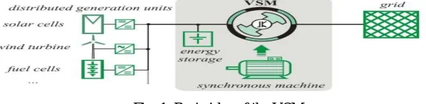
[image:2.612.157.456.616.689.2]The diffusing utilization of the renewable energy resources is driven by the limited fossil energy store on the one hand and the exacerbated environmental issues as well as energy politics on the other hand. The diversity of the renewable energies and its strong dependence on the geological location and meteorological situation make the change that the electricity will be generated more and more by small distributed generation (DG) units. Most of these DG technologies only consider supplying maximum power into the grid but taken the stability of the power system not into account. Generally, a few small-size DG units will not influence the safe operation of the power network in the presence of large centralized power stations thus their influences can be neglected. But with a larger numbers of DG units with higher capacities, the overall dynamics of power systems are significantly affected [4]. Therefore the solutions to improve the power system stability and at the same time ensure the increasing integration of the DG units are necessary. The concept of virtual synchronous machine describes a new type of grid feeding inverter, which operates with a storage system entirely as an electromechanical synchronous machine. The basic idea of the VSM bases on reproducing the static and dynamic properties of a real synchronous machine on a power electronic interface between a DG unit and the grid, in order to inherit the advantages of a synchronous machine in consideration of power system stability such as adjustable active and reactive power, dependence of the grid frequency on the rotor speed and the effect of the rotating mass and damping windings as well as stable operation with a high parallelism level. Fig. 1 illustrates the basic idea of the VSM.
Fig. 1. Basic idea of the VSM.
whether both VSM-Methods are able to be operated in a stand-alone grid. Finally the relevant conclusions are drawed at the end of this paper.
II. IMPLEMENTATIONMETHODSOFTHEVSM
In this section two methods to implement the VSM on an inverter will be discussed here. They will be called VSM -Method 1 and 2 in this paper. The VSM Method 1 was already presented in [1][2][3] and will be applied as a reference here for the comparison with the VSM -Method.
A. VSM -Method 1 using voltage-to-current model
The complete VSM functional chain is shown in Fig. 2. It starts with the real-time measurement of the grid voltage to feed the virtual synchronous machine algorithm on the process computer and delivers the stator currents of the virtual synchronous machine as the results which presented as process variables. The fast hysteresis controlled inverter carries over the current signals to drive these currents at the grid immediately.
[image:3.612.165.464.244.411.2]The synchronous machine model used in this method is shown in Fig. 3 and was introduced in [5].
Fig. 3. Block diagram of the VSM -Model 1.
B. VSM -Method 2: using current-to-voltage model
inductors Lf and capacitors Cf are used to filter the harmonics of the output voltage of the inverter. Fig. 4 demonstrates the basic concept of the VSM -Method 2. Fig. 4. Concept of the VSM -Method 2.
[image:4.612.181.440.169.390.2]The synchronous machine model used in VSM Method 2 is a current-to-voltage model as shown in Fig.5. This is an inverse model of VSM -Model 1, namely the current as input and voltage as output. After the model inversion a differentiator occurs, which could lead to instability of the model. Hence a low-pass filter should be applied to reduce the disturbance of the model input (current I grid) and enable a stable computing process of VSM -Model 2.
Fig. 5. Block diagram of the VSM -Model 2
III. SIMULATION PARAMETERS
[image:4.612.188.425.468.696.2]The simulations presented in this paper were carried out in Matlab-Simulink. The important parameter setups during the simulations are shown in table I.
Table I. – Simulation parameters Voltage of DC site ±350V
Nominal frequency 50Hz Nominal phase voltage
(rms) 230V
Inductor Lf 4Mh Capacitor C 5µF Tolerance band of
hysteresis
controller for phase currents
±1A
Switching frequency of the
IGBT inverter
2,8kHz ~ 15kHz for VSM -Method 1
15kHz for VSM -Method 2
using PWM controller Time step for simulation 1µs
IV. aPARALLEL OPERATION WITH STIFF GRID
of the VSM -Method 2 are compared with the reference VSM -Method 1 by simulation results.
A. Synchronisation of the VSM with the grid
The VSM must be synchronized with the grid firstly before connecting to the grid, since an adverse switching could lead to large transient currents between the VSM and the grid, which could damage the equipments. Due to the different control concepts, both VSM -Methods will be synchronized with the grid in different ways.
Since the currents in the VSM -Method 1 are controlled directly by using a hysteresis controller, the transient currents can be regulated nearly to zero by setting the reference currents closely to zero. After that, the VSM can be connected to the grid, because the hysteresis controller and IGBT-module track the reference currents very fast.
Compared to the VSM -Method 1 the synchronizing of the VSM -Method 2 is more complicated, since the currents between VSM and grid cannot be directly controlled but only indirectly through the voltage controller. In this case the VSM behaves as a voltage source. Therefore the VSM can be synchronized with the grid in the same way as a real synchronous generator. Thereby the following parameters should be adjusted according to the grid voltage at PCC: amplitude, phase and frequency. The voltage difference between VSM and grid should be so small that transient currents values are acceptable.
B. Power setting of the VSM
The power of the VSM can be set similarly as a real synchronous machine. The following shows separately the active and reactive power setting of both VSM -Methods with discussions.
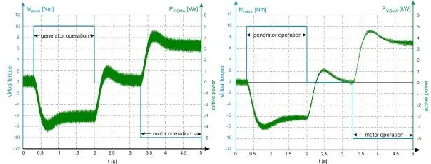
1) Active power setting of the VSM: The active power of the VSM can be easily set by adjusting the model parameter Mmech, which is called virtual torque.
[image:5.612.91.526.358.524.2]Fig.6 shows the active power setting of the VSM for both methods.
Fig. 6. Active power setting of the VSM (left: VSM Method 1; right: VSM -Method 2)
The simulation results prove that the VSM -Method 2 is able to behave the same dynamic property as the VSM-Method 1. A positive torque means the VSM supplies an active power into the grid and operates as a generator. For a negative torque the active power will be taken from the grid and then the VSM operates as a motor. The only difference between both VSM methods consists in the noise component of the Pvsima. In VSM-Method 1, because of the hysteresis controller, which works at a fixed tolerance band, the switching frequency of the inverter is not constant but varying within a frequency band. Therefore there are harmonics with different frequency terms in the output currents. However, in Method 2, by using PWM-controller a constant switching frequency can be reached thus the output of the inverter will be more easily and better filtered by selecting a proper filter.
Fig. 7. Reactive power setting of the VSM (left: VSM Method 1; right: VSM-Method 2).
Both VSM -Methods supply a capacitive reactive power while over excited and an inductive reactive power while under excited. The VSM -Method 2 has the same dynamic property as the VSM -Method 1 but the output signal has a lower noise because of the PWM-controller compared to VSM -Method 1. The power of the VSM can be regulated dynamically during the changes of the grid frequency and voltage, in case that the frequency and voltage controls are added to the VSM[6]
V. FAILURE OF STIFF GRID – ISLAND MODE
In the following section the island mode of both VSM Methods will be investigated by simulation. At the beginning both VSM s are connected with the grid. After 0.2s the VSM s will be switched off from the grid and they should build a local stand-alone grid. In all simulations the VSM didn’t have frequency and voltage control mechanisms.
A. Island mode of the VSM -Method 1
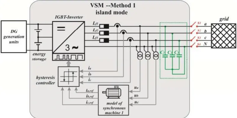
For the parallel operation with the stiff grid, the capacitors which are shown in green color in Fig. 8 are not necessary in the VSM -Method 1, because it presents itself as a current source. If there is no stiff grid in this configuration, then the VSM cannot operate as a synchronous machine, since no currents flow in the inductors and the hysteresis controller cannot work properly. Therefore, extra capacitors must be installed in the VSM for the island function, see Fig. 8.
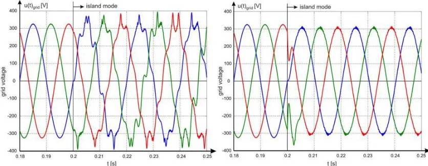
[image:6.612.110.511.491.691.2]Fig. 9 shows the simulation results under the condition that the VSM changed from grid connected mode to island mode in cases of without and with a load.
Fig. 9. Output voltage of the VSM -Method 1 by changing to island mode (filter capacators C = 5µF, left: VSM without load; right: VSM with a load).
It is obviously to see that the VSM has built the voltage continuously after switching off the public grid. Without a load the voltages have a large distortion, because the switching frequency of the hysteresis controller is varying and the LC-filter could not filter out all frequency parts; whereas the VSM under island mode with a resistive load, the harmonics could be damped almost completely and rapidly. Another way to reduce the harmonics is to choose larger capacitors and make sure that the corner frequency of the LC-filter is under the minimal switching frequency of the hysteresis controller.
C. Island mode of the VSM -Method 2
[image:7.612.65.529.440.612.2]For VSM -Method 2 a modification of the hardware configuration is not necessary. The VSM operates here as a voltage source. Under the same simulation conditions the VSM-Method 2 provided following results illustrated in Fig.10.
Fig. 10. Output voltage of the VSM-Method 2 by changing to island mode (filter capacitors C = 5µF, left: VSM without load; right: VSM with a load).
VI. CONCLUSIONS
This paper presents a new method to implement the VSM on the PWM controlled inverter by using a current-to-voltage model. A comparison of this new method with VSM -Method 1 by using a voltage-to current model on the hysteresis controlled inverter has been performed by simulation results. It has been proved that the VSM-Method 2 is able to behave almost the same static and dynamic properties such as flexible power setting, energetic reproducing the virtual rotating mass and virtual damping in a parallel operation with the public grid as the VSM -Method 1. Both VSM -Methods can be operated under an island mode. The VSM -Method 2 can achieve a better voltage quality compared to the VSM -Method 1, which needs larger capacitors in order to having the same voltage quality. For building a stable island grid the frequency and voltage controller should be applied in both VSM -Methods. Considering the widely applied PWM controlled inverters in the current market, the VSM -Method 2 is tended to be more easily utilized.
REFERENCES
[1] Xiaodong Liang “Emerging Power Quality Challenges Due to Integration of Renewable Energy Sources” IEEE Transactions on Industry Applications, Year: 2017, Volume: 53, Issue: 2 Pages: 855 – 866.
[2] J. Breckling, Ed., The Analysis of Directional Time Series: Applications to Wind Speed and Direction, ser. Lecture Notes in Statistics. Berlin, Germany: Springer, 1989, vol. 61.
[3] S. Zhang, C. Zhu, J. K. O. Sin, and P. K. T. Mok, “A novel ultrathin elevated channel low-temperature poly-Si TFT,” IEEE Electron Device Lett., vol. 20, pp. 569–571, Nov. 1999.
[4] M. Wegmuller, J. P. von der Weid, P. Oberson, and N. Gisin, “High resolution fiber distributed measurements with coherent OFDR,” in Proc. ECOC’00, 2000, paper 11.3.4, p. 109.
[5] R. E. Sorace, V. S. Reinhardt, and S. A. Vaughn, “High-speed digital-to-RF converter,” U.S. Patent 5 668 842, Sept. 16, 1997. [6] (2002) The IEEE website. [Online]. Available: http://www.ieee.org/
[7] M. Shell. (2002) IEEEtran homepage on CTAN. [Online]. Available: http://www.ctan.org/tex-archive/macros/latex/contrib/supported/IEEEtran/ [8] FLEXChip Signal Processor (MC68175/D), Motorola, 1996.
[9] “PDCA12-70 data sheet,” Opto Speed SA, Mezzovico, Switzerland.
[10] A. Karnik, “Performance of TCP congestion control with rate feedback: TCP/ABR and rate adaptive TCP/IP,” M. Eng. thesis, Indian Institute of Science, Bangalore, India, Jan. 1999.
[11] J. Padhye, V. Firoiu, and D. Towsley, “A stochastic model of TCP Reno congestion avoidance and control,” Univ. of Massachusetts, Amherst, MA, CMPSCI Tech. Rep. 99-02, 1999.