©IJRASET 2015: All Rights are Reserved
153
LTE Downlink Channel Estimation Using Music
Algorithm
Arpita Sharma1,Rekha Gupta2 1,2
Madhav Institute of Technology and Science, Gwalior
Abstract--3GPP LTE is the evolution of the UMTS in response to ever‐increasing demands for high quality multimedia services according to users’ expectations. Since downlink is always an important factor in coverage and capacity aspects, special attention has been given in selecting technologies for LTE downlink. This paper aims at channel estimation for LTE downlink using music algorithm. Music algorithm is an efficient technique used for frequency response estimation in far spaced channels .Maximum likelihood estimation haven been evaluated for different channel models in LTE downlink. Performance of music algorithm has been measured in terms of Bit Error Rate (BER) and Symbol Error Rate (SER).
Keywords: LTE, Music Algorithm, Channel Estimation, OFDM, PSA Model.
I. INTRODUCTION
In modern world, requirement of high data rate communication has become inevitable. Applications such as streaming transmission, video images, and World Wide Web browsing require high speed data transmission with mobility. In order to
fulfill these data requirements, the 3rd Generation Partnership Project (3GPP) [1][2] introduced Long Term Evolution (LTE),
to provide high speed data rate for mobile communication. The LTE system affords an important effective bit rate and allows increasing system capacity in terms of numbers of simultaneous calls per cell. In addition, it has a low latency compared to 3G/3G + networks. It offers a theoretical speed of 100 Mbits/ s in the Downlink and 50Mbits/s in the Uplink transmission. The LTE uses Orthogonal Frequency Division Modulation (OFDM) and Orthogonal Frequency Division Modulation multiple access technique (OFDMA) in the downlink transmission [3]. The OFDM provides the signal transmitted Robustness against the multipath effect and can improve the spectral efficiency of the system [4][5]. On the other hand, the implementation of MIMO system increases channel capacity and decreases the signal fading by sending the same information at the same time through multiple antennas [5]. The combination of these two powerful technologies (MIMO-OFDM) in the LTE system improving thus the spectral efficiency and throughput offered without increasing resources for base bands and power output. To best exploit the power of MIMO-OFDM technology, it is imperative to manage at best the estimation of the channel coefficients; this operation is ensured by the interpolation of pilots[3]. In an OFDM system, the transmitter modulates the message bit sequence into PSK/QAM symbols, performs IFFT on the symbols to convert them into time-domain signals, and sends them out through a (wireless) channel. The received signal is usually distorted by the channel characteristics. In order to recover the transmitted bits, the channel effect must be estimated and compensated in the receiver. Each subcarrier can be regarded as an independent channel, as long as no ICI (Inter-Carrier Interference) occurs, and thus preserving the orthogonality among subcarriers. The orthogonality allows each subcarrier component of the received signal to be expressed as the product of the transmitted signal and channel frequency response at the subcarrier. Thus, the transmitted signal can be recovered by estimating the channel response just at each subcarrier. In general, the channel can be estimated by using a preamble or pilot symbols known to both transmitter and receiver, which employ various interpolation techniques to estimate the channel response of the subcarriers between pilot tones. In general, data signal as well as training signal, or both, can be used for channel estimation. In order to choose the channel estimation technique for the OFDM system under consideration, many different aspects of implementations, including the required performance, computational complexity and time-variation of the channel must be taken into account[7]. The paper is organised as follows section I gives the introduction about LTE. Section II explains Pilot based Channel Estimation. Section III explains PSA model. Section IV explains the Music Algorithm. Section V gives the idea about ITU Channel Model. Section VI shows the Simulation Result. Finally the Paper is Conclude in Section VII.
II. PILOT BASED CHANNEL ESTIMATION
consisting of reference symbols is determined using statistical methods including Least Squares (LS) and Minimum Mean Squares (MMSE) estimates. Different pilots assisted channel estimation schemes can be employed for the estimation of the channel effects on the transmitted signal. The response of the channel at the data subcarriers is subsequently determined by interpolation[7].
Depending on the arrangement of pilots, three different types of pilot structures are considered: Block Type
Comb Type Lattice Type
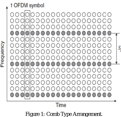
A. Comb Type Arrangement
Comb-type pilot arrangement is depicted in Figure 1. In this type, every OFDM symbol has pilot tones at the periodically-located subcarriers, which are used for a frequency-domain interpolation to estimate the channel along the frequency axis. Let
Sf be the period of pilot tones in frequency. In order to keep track of the frequency-selective channel characteristics, the pilot
symbols must be placed as frequently as coherent bandwidth is. As the coherence bandwidth is determined by an inverse of
the maximum delay spread σmax, the pilot symbol period must satisfy the following inequality:
[image:3.612.202.415.306.512.2]≤ 1
Figure 1: Comb Type Arrangement.
III. PSA SYSTEM MODEL
In this section, PSA channel estimation of frequency response of the downlink channels is presented. A complex baseband discrete time model is assumed in this section. In particular, we utilize the simplified tapped delay line model of [7] and
denote ℎ( ) = [ℎ( , ),ℎ( , ), … … … . .ℎ( , )]T
as the multipath gain vector for Rayleigh faded sample space (SS)
channel of the user in the ith block. The number of multipath L is equal to the channel length (⌊ ⁄ ⌋+ 1), where T is the
sampling interval and Tmax is the maximum excess channel delay. In wireless communication, the channel length is limited to
few samples, hence it is more appropriate to estimate the h(i) and then determine the channel frequency response as the
fourier transform of the h(i). The channel frequency response at nth subcarrier of the user SS channel is given by
( , ) =∑ ℎ( , ) exp − , 0≤ ≤ −1 (1)
©IJRASET 2015: All Rights are Reserved
155
and the corresponding received symbols, the frequency for the p subcarrier is estimated using least squares (LS) method as
, = , / ,
= , + , , (2)
The term , is defined as the LS estimate of , . Corresponding to all P pilots, a vector , consisting of the LS
estimates at pilot subcarriers of the user is defined as
= ( , ), ( , ) … … … , (3)
Using (2) and (3), we can define , as
, = + = ℎ+ (4)
HP is a vector which consists of the frequency responses calculated at the pilot subcarrier
frequencies. = ( , )⁄ ( , ), … … … … . , , is a P×1 vector with zero mean and covariance matrix
= ( /A)IP, where ‘A’ is the pilot power and IP is an identity matrix. GP is a P× L FT matrix with elements .
[ ] , = −2 / , 0≤ ≤ −1, 0≤ ≤ −1 (5)
Next, the channel estimates for the remaining subcarriers are derived from these LS estimates by means of interpolation over the entire frequency grid. Since we consider only frequency domain interpolation, we omit the time index in the following expressions. Every user is allocated P pilots, where P≥ the number of channel taps. For a given value of P, the MSE in
estimation process can be minimized by using uniformly spaced pilot symbols with separation interval of N/P i.e., −
= ⁄ , 1≤ ≤ −1. In the following subsections, we describe channel estimation methods. These methods differ
from each other regarding the interpolation technique.
A. Maximum Likelihood (MS) Estimation
The ML estimation is simple to implement as it does not require prior information about channel covariance matrix. The frequency domain interpolation using the LS estimates is performed as follows:
Stacking the channel estimate vectors P,lsfrom all users, we arrive at super vector of the LS estimates
, = ℎ+ (6)
The ML estimate of h is derived as follows
ℎ = ( ) , = ( ) , (7)
Where DP is a square matrix DP= (GP) H
GP
The frequency response vectors {ℎml} of the user is determined as
= ℎ (8)
GN is a N× L DFT matrix with element
[ ] , = (−2 / ), 0≤ ≤ −1, 0≤ ≤ −1 (9)
The MSE in the estimation of the lth path gain of the user is given by
= [( ) ], = [( ) ], (10)
Where
= {∑ | ( )| }/ (11)
and
= {∑ | ( )| }⁄ (12)
= − −
IV. MUSIC ALGORITHM
The multiple signals Classification (MUSIC) method is also a noise subspace frequency estimator. To develop the method, let us first consider the “weighted” spectral estimate [8,9].
( ) =∑ | ( ) | (14)
Where { , = + 1 … … … … . . }are the eigenvectors in the noise subspace, {wk} are a set of positive weights and the S(f)
is the complex sinusoidal vector.
( ) = [1, , … … … ( ) ] (15)
Note that = , ( )≡ so that at any one of the sinusoidal frequency componentsof the signal, we have
( ) = 0, = 1,2,3 … … … . . (16)
Hence the reciprocal of P(f) is a sharply peaked function of frequency and provide a method for estimating the frequency of the sinusoidal components thus
( )=∑ ( ) (17)
Although theortically 1⁄ ( ) is infinite at = , in practice the estimation errors result in finite values for 1⁄ ( )at all frequencies. The MUSIC sinusoidal frequency estimator proposed in schmit, is a special case of the equation (3)in which the weight wk = 1 for all k. Hence
( ) =
∑ ( ) (18)
V. ITU MULTIPATH CHANNEL MODELS
International Telecommunication Union (ITU) proposed multipath channel models for the development of 3G IMT 2000 group of radio access systems which are similar in structure to the 3GPP multipath channel models. ITU proposed set of test environments that cover all the scenarios according to user mobility. These models greatly helped system designers and network planners for evaluating performance. In this Paper ITU standard channel models for pedestrian and vehicular environments are used[8].
A. ITU Pedestrain Channel Models
For Pedestrain environments ITU proposed channel models Pedestrain A and Pedestrain B are used. The average power and the relative delay for multipath channels based on ITU recommendations are given in table 1(in Appendix).
B. Extended ITU Models
The extended ITU models for LTE were given the name of Extended Pedestrian‐A (EPA), Extended Vehicular‐A (EVA) and Extended TU (ETU). These channel models are categorised on the basis of low, medium and high delay spread where low delay spreads are used to model indoor environments with small cell sizes while medium and high delay spreads are used to model urban system (table 2 in Appendix)
VI. SIMULATION RESULT
157
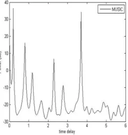
Figure2: Path Delay Estimation of ITU Pedestrain B Model Using Music Algorithm.
[image:6.612.241.369.81.216.2]The Path delay of ITU Padestrain A Model and the Extended Typical Urban Model is given in Appendix.
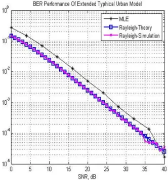
Figure 3: BER Analysis For Pedestrain B Model.
[image:6.612.219.388.459.678.2]Figure 5: BER Analysis for Extended Typhical Urban Model.
VII. CONCLUSION
The Channel Estimation using Music Algorithm on PSA Channel Model has been carried out. The figure shows the Bit Error Rate Analysis of the Various ITU Models. The BER of All the Models Compared with the BER of Rayleigh Channel.
REFERENCES
[1] 3rd Generation Partnership Project, Technical Specification Group Radio Access Network; evolved Universal Terrestrial Radio Access(UTRA): Base Station (BS) radio transmission and reception, pp.22– 33, TS 36.104, V8.7.0, 2009.
[2] 3rd Generation Partnership Project, Evolved Universal Terrestrial Radio Access (E-UTRA); User Equipment (UE) radio transmission and reception, pp. 22 – 33, ARIB STD-T63-36.101, V8.4.0, 2008.
[3] 3rd Generation Partnership Project, Technical Specification Group Radio Access Network; evolved Universal Terrestrial Radio Access
(UTRA): Physical Channels and Modulation layer, pp. 55 – 67, TS 36.211, V8.8.0, 2009.S. Caban, Ch. Mehlfuhler, M. Rupp, M. Wriliich, “Evolution of HSDPA and LTE”, Ltd. Published 2012 by John Wiley &Sons,.
[4] S. Sesia, I. Toufik, and M. Baker, LTE – The UMTS Long Term Evolution from Theory to Practice, 1st
ed, Jonh Wiley and sons, LTD.UK;2009 [5] Z. Lin, P. Xiao, B. Vucetic, and M. Sellathurai, “Analysis of receiver algorithms for lte scfdma based uplink systems,” IEEE Transaction on Wireless Communications, vol. 9, pp.60–65, 2010.
[6] J. F. ValenzuelaValdes, M. A. Garcia Fernandez, A. M. Martinez Gonzalez, and D. A.Sanchez- Hernandez, “Evaluation of true polarization diversity for mimo systems,” IEEE Transaction on Antennas and Propagation, vol. 58, pp. 2746–2755, 2009.
[7] Yong soo choo,Jeakwon Kim,won young yen and Chang Gu Kang,”MIMO- OFDM Wireless communication With MATLAB” Willey Publication. [8] Power Delay Profile Estimation for MIMO-OFDM, Systems over Time-Varying Multipath Channels, Xiaoqun Gong, Chunming Zhao, Wei Xu, Ming Jiang,National Mobile Communications Research Laboratory, Southeast University, Nanjing, China,210096
[9] John G Proakis, “ Digital Communication” Pearrson Publication 2nd Edition New Delhi India
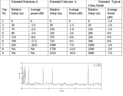
[image:7.612.223.389.76.253.2]APPENDIX
Table 1: ITU Pedestrain Channel Model
Pedestrain A Pedestrain B
Tap No.
Relative Delay
(ns)
Average power
(dB)
Relative Delay
(ns)
Average Power (dB)
1 0 0 0 0
2 110 -9.7 200 -0.9
3 190 -19.2 800 -4.9
4 410 -22.8 1200 -8
5 NA NA 2300 -7.8
159
Table 2: Power Delay Profile of Various Extended Model.
Tap No.
Extended Pedestrain A Extended Vehicular A Extended Typical
Urban Model Relative
Delay (ns)
Average power (dB)
Relative Delay (ns)
Average Power (dB)
Relative Delay (ns)
Average Power (dB)
1 0 0 0 0 0 -1.0
2 30 -1.0 30 -1.5 50 -1.0
3 70 -2.0 150 -1.4 120 -1.0
4 80 -3.0 310 -3.6 200 0.0
5 110 -8.0 370 -0.6 230 0.0
6 190 -17.2 710 -9.1 500 0.0
7 410 -20.8 1090 -7.0 1600 -3.0
8 NA NA 1730 -12.0 2300 -5.0
[image:8.612.108.506.117.428.2]9 NA NA 2510 -16.9 5000 -7.0
Figure 6: Path Delay Estimation of Extended Typical Urban Using Music Algorithm.
[image:8.612.163.451.448.552.2]