© 2016, IRJET | Impact Factor value: 4.45 | ISO 9001:2008 Certified Journal
| Page 126
Effect of PI controller parameters on the performance of
Shunt Active Power Filter
Rajesh Babu Yamarthi
1, R.Srinivasa Rao
2, P.Linga Reddy
31
EEE Department, KKR & KSR Institute of Technology and Sciences,Guntur,AP,India
2
Department of EEE, University college of Engineering, JNTU Kakinada, AP,India
3
Department of EEE, KL University, Vaddeswaram, AP,India
---**---Abstract -
This paper proposes a novel predictive controltechnique to achieve better dynamic performance of Shunt Active Power Filter (SAPF). In a non linear environment SAPF can used to compensate harmonics and reactive power efficiently. The Dynamic performance of SAPF mainly depends on the controller used to extract the harmonic content in source current. Most of the control techniques are require number of complex transformations. In this paper a simple and easy to implement synthetic sinusoid generation technique by sensing the load current is proposed. The working of proposed controller is verified at different load conditions.
Key Words: Harmonics, Shunt Active power Filter, PI controller, THD
1.INTRODUCTION
In the recent years power electronic converters are more widely applied in domestic, commercial and industrial loads. This leads to harmonic pollution in utility side. This harmonic pollution mainly affects the distribution networks leading to problems like non sinusoidal current flows to sensitive loads, electromagnetic interferences, protection misoperation, insulation failures, harmonic resonances... etc. Traditionally shunt passive filters are used to compensate harmonics. In spite shunt passive filters creates problems like overload, detuning due to aging of their components, appearance of resonances with the power system for a harmonic below the tuned frequency, fixed filtering characteristic, etc. Active power filters (APF) are being investigated and developed as a viable alternative to passive filters. An APF can do elimination of current harmonics, compensation of reactive power and voltage regulation and improves power quality. APFs are broadly classified in to two groups such as Series APF and Shunt APF. Series APF is used to eliminate the voltage harmonic and Shunt APF is used to eliminate current harmonics [1]-[3].
Shunt Active Power Filter (SAPF) is the device designed to improve the quality of the waveform in the current signal in distribution networks. The operation of SAPF mainly depends on reference-generation controller techniques. In general reference-generation techniques may be broadly
classified as time-domain and frequency-domain approaches. Fast Fourier transform (FFT), recursive discrete Fourier transform (RDFT), and wavelet-based approach are the three widely used frequency-domain approaches [4]. The limitations of the frequency-domain approaches are problem of aliasing and synchronizing of Sampling instant and zero crossing of fundamental. In time domain approach instantaneous active and reactive Theory and Synchronous Reference Frame Theory are widely used. Akagi et al. [5] proposed the instantaneous reactive power theory (p-q theory)for estimating the reference compensation currents required to inject into the network at PCC where the nonlinear load is connected. S. Bhattacharya, et al. [6] presented a synchronous reference frame technique (SRF theory) for obtaining sinusoidal source currents under non linear load condition. Advantages of time domain approaches are easy in implementation and good steady-state performance with ideal supply voltage. Major disadvantages are delay in compensation; uses large number of voltage and current transducers, compensation is poor in case of distorted supply voltage [7].
Gary W. Chang, et al. [8] proposed a methodology which works under imbalanced source voltages. Most of these control methods involves number of transformations and hence implementation becomes difficult. System control also complex with this methodologies.Duke.et al. [9] has proposed a simple synthetic sinusoid generation technique to determine compensating currents by sensing the load currents.
In this Paper a novel methodology adapted by the line currents is proposed. Traditional methodologies like p-q theory and SRF theory are discussed and compared with proposed PI Controller-Based predictive Algorithm. The proposed controller is applied and verified the performance under different operating conditions.
2. Shunt Active Power Filter
© 2016, IRJET | Impact Factor value: 4.45 | ISO 9001:2008 Certified Journal
| Page 127
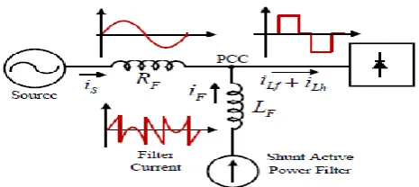
at PCC. Model Block diagram of SAPF is shown in Fig.1. The [image:2.595.49.282.252.356.2]SAPF turns the non-sinusoidal source current into sinusoidal waveform by injecting the harmonic currents demanded by the non-linear load. Current harmonics can be eliminated with SAPF. The main aim of SAPF is to mitigate harmonics in Load current so that source current remains in phase with Source Voltage. In other words only fundamental frequency remains in source current. The SAPF also compensates reactive power and improves power factor due to its capacitive nature. Zero active power exchanges between SAPF and grid. The source only supplies the active power consumed by the load.
Fig -1.Block diagram of Shunt Active Power Filter Due to its capacitive character, the shunt active filter is also used to generate reactive power and to compensate the power factor. The preceding fact imposes a null active power exchange in the APF and implies that the source must supply the active power consumed by the load. One aim of the active filter is the harmonic mitigation of the load current so that only the fundamental frequency remains in the grid.
3. Proposed control algoritham
[image:2.595.55.267.619.724.2]As stated before, when the utility voltage is purely sinusoidal, the performance of the algorithms based on power theories are the best choice. However, under non sinusoidal voltage, the waveform quality of the resulting signal drops dramatically. Fig 2 shows the basic compensation principle of a shunt Active power filter. A simple synthetic sinusoid generation technique is proposed as follows. This methodology works under imbalanced source voltages
Fig -2. Block diagram of Shunt Active Power Filter When nonlinear load is connected to the distribution system, the instantaneous load power can be given by
( ) ( ) ( )
where ( ) source voltage and ( ) is instantaneous load current.
The instantaneous source current is given by
( )
The instantaneous current can be written as
( ) ( ) ( ) (15) When a nonlinear load is applied the load current has two
components.They are fundamental component and harmonic components, which can be expressed as
( ) ∑ ( )
( ) ∑ ( )
Substitute equation (14) and equation (16) in equation (13), then The instantaneous load power can be given as
( ) ( ) ( )
+
∑
( )
= ( ) ( ) ( )(5)
from (5), the real power drawn by the load is
( ) = ( ) ( ) (17) From (17), the current supplied by the source, after compensation is
( ) ( ) ⁄ ( ) (18)
Where the peak value of the loss current.For harmonic
mitigation, SAPF is must provide compensating Current
( )such that ( )must be in phase with the utility voltage and purely sinusoidal. The compensating Current can be given as
( ) ( ) ( ) (19) Hence, for accurate and instantaneous compensation, it is necessary to estimate ( ) This ( ) is the fundamental component of ( )as the reference current. The peak value of the reference current can be calculated by controlling the
dc-side capacitor voltage.
Irrespective of the load current nature, Ideal compensation requires the supply current to be sinusoidal and in phase with the source voltage. The source currents, after compensation, can be given as
( )
( ) (20)
Where is the amplitude of the desired source current,
© 2016, IRJET | Impact Factor value: 4.45 | ISO 9001:2008 Certified Journal
| Page 128
to be calculated. Fig. 3 shows the schematic diagram ofproposed control scheme.
Fig -3. controller block diagram
4. SIMULATION RESULTS
Simulations are performed using MATLAB® Simulink. Simulated results are analyzed based fitness function and optimization algorithms. The parameters taken for simulation are: VS = 230V , f=60Hz , Rf = 0.1ohms ,Lf = 0.66mH, Cdc = 2000mF , Vdcref = 200V ,Rs = 1Ω ,Ls =0.15mH ,RL = 10Ω , LL=20mH.
1.Dynamic Performance of SAPF
Balanced sinusoidal source voltages are considered. For simple analysis phase a quantities are considered.
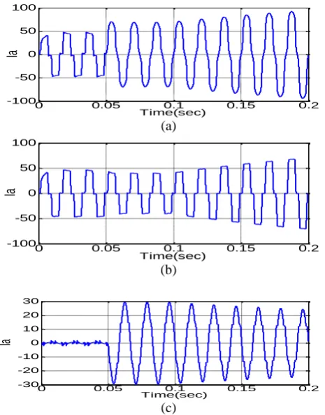
Switch-on Response: The compensator is switched on at 0.05s. Supply current, load current and filter current for phase "a" are shown in Fig.4. It is observed that the supply current is distorted until SAPF is turn on i.e at 0.05 sec. Up to 0.05 sec both source current and Load current are distorted. When SAPF is switched on at 0.05 sec, SAPF starts injecting compensating current and hence source current becomes sinusoidal. The THD of source current without SAPF is 23.92% and THD of source current with SAPF is 13.10%.
(a)
(b)
(c)
Fig-4. Switch on response of the SAPF. (a)Supply Current (b)Load Current (c) Injected Current
2. Transient Response:
The SAPF with proposed controller giving best performance in steady state. However it is worthwhile to establish its reliability for transient conditions. The load is increased suddenly at 0.15sec. The load current waveform and source current waveform are given in Fig.5.
(a)
(b)
[image:3.595.316.549.99.207.2](c)
Fig-5.Transient response of the SAPF. (a)Supply Current (b)Load Current (c) Injected Current
In the Fig.6. it is observed a smooth changeover from the old condition of the load to its new load. During both old and new load conditions, supply current is close to sinusoidal shape.
1. Unbalanced Case
The performance of SAPF is also verified for Unbalanced case. Three phase unbalanced voltage is applied as source and observed Source voltage waveform, Source current waveform and Load current. Fig .6. shows the performance of the system when an unbalanced source is applied.
0.02 0.04 0.06 0.08
-50 0 50
Time(sec)
Ia
bc
0.02 0.04 0.06 0.08
-50 0 50
Time(sec)
Ia
bc
0.02 0.04 0.06 0.08
-30 -20 -10 0 10 20 30
Time(sec)
Ia
bc
0 0.05 0.1 0.15 0.2
-100 -50 0 50 100
Time(sec)
Ia
0 0.05 0.1 0.15 0.2
-100 -50 0 50 100
Time(sec)
Ia
0 0.05 0.1 0.15 0.2
-30 -20 -10 0 10 20 30
Time(sec)
[image:3.595.52.264.131.218.2] [image:3.595.313.546.304.601.2]© 2016, IRJET | Impact Factor value: 4.45 | ISO 9001:2008 Certified Journal
| Page 129
(c)(b)
(c)
Fig.6.Unbanced case response of the SAPF. (a)Supply Voltage (b)Supply Current (c) Load Current
3. Response with change in PI controller gains.
In the proposed controller, The PI controller is used to process the error between The DC side capacitor voltage and reference voltage. PI controller gives the amplitude of the desired source current. Unit sine vectors are generated from the source voltages. Multiplication of peak value with unit sine vectors gives the reference currents. The step change response for some of the selected values of KP and Ki are presented in Table I. the values of Kp and Ki are decided by suitably considering the overshoot and settling time in transient response for a step change in dc voltage reference. The comparison of DC capacitor voltage for both cases of gain coefficients is given in Fig.7.
Fig-7 .The comparison of the DC capacitor voltage
Table- I : THD cpmparision
Table- II : PI controller coefficients
The THD comparision is given in Table-1. The proposed PI controller coeffients are given in Table-2. Detailed Harmonic Analysis is given in Table 4.Hence the performance of proposed controller is depending on selected values of Kp and Ki.
5.Conclusion
The proposed controller based shunt active power filter has been studied to improve the power quality by compensating harmonics and reactive power requirement of the nonlinear load. The SAPF has good steady state and transient responses. The THD of source current without SAPF is 23.92% and THD of source current with SAPF is 13.10%. The performance of the SAFP has been examined for variation of PI controller gain coefficients. With best selection of gain constants, the performance of SAPF can be improved. The THD of the source current with best PI controller coefficients is well below 5%, the harmonic limit imposed by the IEEE-5 19 standard.
REFERENCES
[1]. H. Akagi, Y. Kanazawa, and A. Nabae, “Instantaneous reactive power compensators comprising switching devices without energy storage components,” IEEE Trans. Ind. Appl., vol. IA-20, no. 3, pp. 625–630, May/Jun. 1984.
[2]. Hirofumi. Akagi, “Trends in Active Power Line conditionors,” IEEE Transactions on power electronics, vol.9, no. 3, pp. 625–630, May/Jun. 1994,pp 263-268. [3]. R.C. Dugan, M.F. McGranaghan and H.W. Beaty, "Power
SystemQuality". New York McCraw-Hill, 1996.
[4]. J. Drieson and R. Belmens, „„Active power filter control algorithms using wavelet based power definitions,‟‟ in Proc. HQPC,2002, vol. 2. pp. 466–471.
[5]. H. Akagi, Y. Kanazawa, and A. Nabae, “Generalized theory of the instantaneous reactive power in three-phase circuits,” in Proc. IEEJ Int.Power Electronics Conf., Tokyo, Japan, 1983, pp. 1375–1386. [6]. S. Bhattacharya, D. M. Divan, and B. Banerjee, “Synchronous frame
harmonic isolator using active series filter,” in Proc 4th Eur. Power ElectronicsConf., vol. 3, 1991, pp. 030–035
[7]. Bhattacharya, C. Chakraborty, and S. Bhattacharya, “Shunt compensation:Reviewing Traditional Methods of Reference Current Generation,” IEEE INDUSTRIAL ELECTRONICS MAGAZINE , SEPTEMBER 2009
0 0.02 0.04 0.06 0.08 0.1
-200 -100 0 100 200
Time(sec)
V
ab
c
0 0.02 0.04 0.06 0.08 0.1
-100 -50 0 50 100
Time(sec)
Ia
bc
0 0.02 0.04 0.06 0.08 0.1
-50 0 50
Time(sec)
Ia
bc
0 0.002 0.004 0.006 0.008 0.01
0 50 100 150 200 250 300
Time(sec)
Vd
c
Case-I Case-II
Controller type Without SAPF Case-I Case-II
THD % 23.92 13.10 3.51
Optimizati
on Method Kp Ki
Case-I 8.1658 9.0673
© 2016, IRJET | Impact Factor value: 4.45 | ISO 9001:2008 Certified Journal
| Page 130
[8]. Gary W. Chang, , and Tai-Chang Shee , “A Novel ReferenceCompensation Current Strategyfor Shunt Active Power Filter Control” IEEE transactions on power delivery, vol. 19, no. 4, october 2004, pp 1751-1758