© 2016, IRJET | Impact Factor value: 4.45 | ISO 9001:2008 Certified Journal | Page 2473
Temperature Analysis of Intel Server by using CFD and
Experimentation
Chetan A Gawande
1, Prof. S.M. Nakate
2, Prasad Chavan
3¹Dept. of Mechanical engineering, MIT Pune, Pune University, pune India
²Dept. of Mechanical engineering, MIT Pune, Pune University, pune India
3
Lead Technician manager, Innovize thermal Solutions Pvt. Ltd. Pune India
---***---Abstract -
The continuous increase of power inputs inelectronic packages and simultaneously reducing the size and weight of electronic products have increased an importance on thermal management issues in electronic industry with recent growth of electronics technology, devices are capable of processing more data within a small period of time. The reliability of electronic components is affected mainly by the temperature at which they operates,. To overcome this issue various effective cooling solution are provided by electronics industry, for the effective thermal performance analysis of server, in this study we compares the results of the analysis of existing server model by providing proper boundary conditions for finding out most heat generating components in system and the validation of result by proper experimentation of server. Temperature analysis is carried by Icepak, commercial CFD software.
Keywords: Computational Fluid Dynamics, Temperature
Analysis, , Ansys Icepak
1. Introduction
Since Intel Corporation launched the first chip, the number of transistors in a chip has increased to over ten million. That means an equivalent surface area of chip produces far greater heat than the previous, leading to an increase in critical heat flux speed. The maximum allowable temperature that can be borne by chip in electronic components is 120°C, with a normal operating temperature of under 70°C. The reliability of electronic components drops by 10% for each increase of 2°C in a normal operating temperature, and high temperature is a major reason for the malfunctioning or shortening life of electronic components. Thus, it is necessary to quickly remove high heat generated by electronic components for a normal operating temperature of under 70°C [1].
Evolving software technology increases the demand on the computer components, such as the central processing unit (CPU) and the chipset, to operate faster. However, a faster CPU and chipsets means more heat production. These undesired situations are most likely to be seen on server components, which have continuous operating conditions. A server is responsible for servicing many clients and its
workload is also greater than an ordinary computer; as such, it possesses multiple CPUs or CPU cores. Multiple core CPUs are widely used and will be dominant in the future. Therefore, server overheating issues have gained greater importance [3].
In the present paper, investigations are carried out on thermal management of Intel server, by using icepak for providing efficient cooling of the server by proper CFD simulations.
2 Literature survey
For better thermal performance and effective flow simulation literature survey is done for different server cooling methods different server components. Serhat Orkun Tan [3], studied different cooling systems used to examine the temperature and performance of the different overheated server components inside the server like CPU and motherboard. T. Abbas [2], explains that Cooling through peripheral means is mainly done using heat sinks to increase the surface area which dissipates heat, fans to speed up the exchange of air heated by the computer parts for cooler ambient air, and in some cases soft cooling. Comparisons between traditional methods of CPU cooling, and new fashions of cooling (like Heat pipes) have been performed. Moreover, Thermal effects on processor performance, has been studied. Effect of time on heat transfer and processor temperature enhancement has been
studied. Jung-Chang Wang [1] talks about different hybrid
cooling methods and the methods currently using to cool the server for effective cooling. The configuration and thermal performance of the heat sinks with inserted heat pipes were studied. He uses experimental procedures to investigate the thermal performance of embedded U-shaped heat pipe and L-shaped heat pipe thermal modules with different fan speeds and heat source areas.
3 Server Details
© 2016, IRJET | Impact Factor value: 4.45 | ISO 9001:2008 Certified Journal | Page 2474
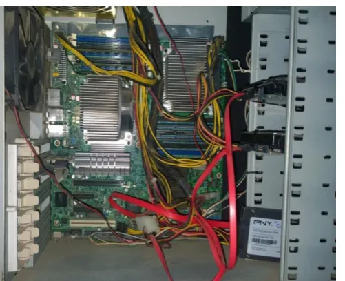
Chipsets DIMM sockets etc. Fig 2 shows every component [image:2.595.300.550.168.469.2]present on Intel workstation board s5520sc. Detail specification all components are given in table, motherboard consist of two xenon processor of E5620 series with heat sink of copper base and aluminium fins mounted on processor to continuously dissipate heat.
Fig. 1:-Interior of Intel workstation system
Fig. 2: - Motherboard placed in server system
The following table 1 indicate the detail specification of the various server Components [6].
[image:2.595.36.287.198.402.2]
Table 1: Details of components inside the server.
Component Quantity Thermal design point (TDP)
Details
CPU 1 80 W Intel processor Xenon E5620
CPU 2 80 W Intel processor Xenon E5620
Motherboard 1 Intel Board s5520sc Sever
Memory 6 2.5 W 1333 MT/s ECC Registered DDR3 Memory (RDIMM),
Chipset 2 27.1 W
5 W
Intel® 5520 Chipset
Intel® 82801JIR I/O Controller Hub (ICH10R) Power Supply 1 1000 W Non redundant
power supply
4 CFD Simulation approach
[image:2.595.39.274.510.685.2]© 2016, IRJET | Impact Factor value: 4.45 | ISO 9001:2008 Certified Journal | Page 2475
Problem Identification1. Define goals
2. Identify domain
Fig 3: CFD Modeling Overview
4.1 Simulation Modelling
A number of simplifying assumptions were made in the modelling. All the smaller and lower power dissipation components on the circuit board were neglected. The main heat generating sources are CPUs and Chipsets in server. The equations that govern incompressible fluid flow and heat transfer used by Icepak are:
For flows general equation for conservation of mass or continuity equation can be written as follows:
Navier-Stokes Equations in X direction,
Y direction,
Z direction,
The energy equation (the temperature distribution)
Where is the density, u,v and w are velocity components, is the velocity vector, p is the pressure, S terms are the source terms, is effective viscosity sum of of laminar viscosity and turbulent viscosity and is effective thermal conductivity
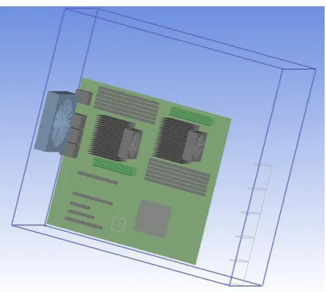
Following fig. 4 shows the detail model of server with different component modeled using ansys icepak.
Pre-Processing
3. Geometry
4. Mesh
5. Physics
6. Solver Settings
Solve Model
7. Compute solution
Post Processing
© 2016, IRJET | Impact Factor value: 4.45 | ISO 9001:2008 Certified Journal | Page 2476
Figure 4: Detail Model of the ServerFigure 5 shows the meshing of all the components presented inside the server cabinet. The finite volume method is adopted for converting governing equations to algebraic equation that can be solved normally. The simple algorithm is used to solve the pressure and convection velocity coupling term. In the solution domain the maximum size of element in three mutually perpendicular directions is less than 1/20 of every domain dimension. The computational domain is discretized into Mesher-HD which conforms to both Icepak primitives and CAD objects meshes that have a total of 536503 nodes and 496291 numbers of elements.
Fig 5: - Meshing of All components
Thermal modelling is one of the major challenges in the design of high power density electronic devices cooling. The simulations are carried to investigate the air flow and heat transfer analysis in Server. Mother board is modelled with isotropic FR4 material. The compact conduction model is used for CPU modelling. The power dissipation is 80 W. Thermal interface material used is thermal grease. PCI cards are modelled as cuboids with flow obstruction and RAM in the DIMMs are modelled with respective power dissipation. Flow blockages by cables are modelled as cuboids to take in to the effects of flow obstruction. The Fans Installed are assumed to perform as per the Fan Curves obtained from respective data sheets the total power distribution is 225.939 W.
Wires and cables are not modeled. The openings (array of hexagonal cut outs) on the Base chassis plates were replaced by equivalent grilles whose flow area is based on the Free Area Ratio calculations .All the PCBs, electronics chips and other thermal components are modeled as homogenous solid materials.
[image:4.595.39.511.482.717.2]5. Experimental Investigations
Figure shows the experimental layout for server machine. T type thermocouple mounted on the different packages inside the server. On the different packages thermocouple end attached with the help of thermal grease. Figure shows the different thermocouple attached on the board packages. These thermocouples are connected to the temperature indicator.
[image:4.595.37.279.489.709.2]© 2016, IRJET | Impact Factor value: 4.45 | ISO 9001:2008 Certified Journal | Page 2477
In this experiment Server present in the Sever room asshown in figure power supply provided to the server. Reading taken while the server operating at fully loaded condition at steady state condition on the different packages.
6. Results and Discussion
The following table shows the experimental and Computational values
Table 3: - Temperature Comparison of different components
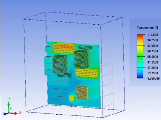
The maximum difference between experimental and Computational is 8.5˚C. The temperature range is 20˚C to 90.774˚C, in the experimental measurement only surface temperature of different packages is measured and in CFD analysis temperature inside the chip is also detected. Figure 7 shows also surface temperature of the board for validation purpose. The following figure 7 shows the temperature field Distribution of the printed circuit board and components for loaded condition.
Fig 7:- Temperature distribution of the board at Loaded condition
Fig 8: - Temperature profile with Heat sink inside server
Following table shows the reading of different components operating at fully loaded condition presented on motherboard using ansys icepack
Table 4:- Temperature at fully loaded condition Packages CFD Experimental
CPU 1 60.034 51.5
CPU 2 54.9068 49.5
DIMM
(Max.)
90.7994 94.2
Packages Temp. at full loaded condition
(˚C)
CPU 1 60.034
CPU 2 54.9068
I/O Hub 83.5546
ICH 82.4481
DIMM 61.3273 - 90.7994
I/O port 28.75 - 32.86
PCIs 20.74 - 28.7615
[image:5.595.308.578.122.324.2] [image:5.595.37.291.550.733.2]© 2016, IRJET | Impact Factor value: 4.45 | ISO 9001:2008 Certified Journal | Page 2478
7 Conclusion & RecommendationThe investigations carried in this paper for temperature analysis using CFD by icepack, commercial CFD software. All the components are operating with the maximum allowable temperature. Highest temperatures were observed on the DIMM socket. A maximum temperature of 90.7944˚C was recorded in steady state condition on the board. Detailed review on the material properties of the heat dissipating components in the Box assembly can improve the thermal prediction in the CFD simulation. The high temperature can be attributed to the absence of effective cooling at that location. Improving the fan capacity and air flow from the present condition might aid in the better ducting of heat.
References
[1] Jung-Chang Wang Superposition method to investigate the thermal performance of heat sink with Embedded heat pipes International Communications in Heat and Mass Transfer 36 (2009) 686–692
[2] T. Abbas, K. M. Abd_elsalam, and KH. Khodairy CPU thermal management of Personal and notebook computer Thermal Issues in Emerging Technologies, ThETA 3, Cairo, Egypt, Dec 19-22nd 2010
[3] SerhatOrkun Tan, HüseyinDemirel Performance and cooling efficiency of thermoelectric modules on server central processing unit and Northbridge Computers and Electrical Engineering 46 (2015) pp46–55.
[4] Stephen Scampoli (2009), "Staying Cool with ANSYS Icepak", ANSYS Advantage, Vol. III, No. 2, pp. 38-39..
[5] G Venkata Subbaiah1, Y Suresh Reddy2, and K Vijay Kumar Reddy3 heat transfer analysis of 1-user server through cfd Int. J. Mech. Eng. & Rob. Res. 2013
[6] Intel® Workstation system sc5650scws Technical
Product Specification Intel order number: E81822-002