© 2016, IRJET | Impact Factor value: 4.45 | ISO 9001:2008 Certified Journal | Page 2895
Numerical Investigation for Wind Turbine Blade For Higher Reynolds
Number For Darrieus Rotor
Parashar S. S
1, Prof. Bhambre V.G.
21
Student, Dept. Of Mechanical Engineering, S.N.D C.O.E & R.C YEOLA, MAHARASHTRA, INDIA
2
HOD Dept. Of Mechanical Engineering, S.N.D C.O.E & R.C YEOLA, MAHARASHTRA, INDIA
---***---Abstract -
In present work an attempt is made toinvestigate the Lift and Drag forces for different Reynolds number and angle of attack for wind turbine blade for three different chord length 5 cm, 10 cm, 15 cm. In present work NACA 0021, NACA0015, NACA0009, NACA4421 airfoil profile is considered for analysis of wind turbine blade. The Lift and Drag forces are calculated at different angle of attack varying from 0 o to 80o for five different higher Reynolds number from 10,000, 40,000, 160,000, 360000 and 800000 by Computational Fluid Dynamics (CFD) analysis. The values of CL and CD at higher Reynolds number is much important in analysis of Darrieus and horizontal axis type of wind turbine blade, still it these values are not available from the literature reviewed . From CFD analysis it is concluded that as Reynolds number increase lift forces and drag forces decreases for particular chord length and if chord length increases CL and CD increases. And Comparison has been done in four blade profile (NACA0021, NACA0015,NACA0009, NACA4421 ) for all three chord length and from that we concluded that NACA 4421 provides maximum lift and drag at higher Reynolds number.
Key Words: Angel of attack, Chord length, Drag coefficient, Lift coefficient, NACA Blade profile.
1.INTRODUCTION
AILY aily huge consumption of electricity in India there is need simple economical device which will produce electricity very fast. This need of modern society will be fulfill by simple three blade wind turbine which is called darrius turbine. Selection of aerofoil shape of blade is the most critical part of a wind turbine design as ultimately blade is responsible for conversion of kinetic energy into mechanical energy. Aerodynamics is a science and study of physical laws of the behavior of objects in airflow and the forces that are produced by airflows. In the early stage, the research on wind turbine blade design was limited on theoretical study, field testing and wind tunnel testing which need a lot of efforts and resources. Due to the development of computer aided design codes, they provide another way to design and analyzed the wind turbine blades. So aerodynamic performance of wind turbine blades can be
analyzed using Computational Fluid Dynamics (CFD), which is one of the branches of fluid mechanics. Aerodynamic studies are quite mature for flows with large Reynolds number. However, large Reynolds number. However, there are not much analytical, numerical or experimental studies available for flows at very high Reynolds numbers. In order to extract the maximum kinetic energy from wind, researchers put much effort on the design of effective blade geometry. Consideration of 2D geometries, i.e., airfoils, for such studies seems to be a good starting point to improve understanding of higher Reynolds number flows.
2.LITERATURE REVIEW
In this regard, some experimental studies are reported in Schmitz F. W., 1967, Sunada S. et al., 1997 [5], Sunada S. et al.,
2002 [6], M Nazmul 2015 [7]. Numerical studies, for analysis
as well as for design and experimental validations of airfoils at ultralow Reynolds number are presented in Kroo and Kunz, 2000, Kunz and Kroo, 2000 [1, 2]. The effects of aerofoil
profile modification on a vertical axis wind turbine performance are presented in by Md Farath Ismail , Krishana vijayrahgavan 2015 [8] . The effect of Blockage-tolerant wind
tunnel measurements for a NACA 0012 at high angles attack is presented by J.M Rainbird , J .Peiro 2015 [9]. From
literature survey, it is observed that, study of lift and drag forces on aerofoil, for very high Reynolds number at angle of attack is not explode more. So, in present work an attempt is made to study the Lift and Drag forces on a wind turbine blade for very high Reynolds number and different angle of attack. In present work NACA 0015 and naca0021 airfoil profile is considered for analysis of wind turbine blade. The Lift and Drag forces are calculated at different angle of attack from 0o to 80o for five different Reynolds number from
10,000, 40000, 160000,360000 and 800000 for three different chord lengths by computational fluid dynamics analysis.
3.MATHEMATICAL EQUATIONS
3.1 Lift Coefficient
(C
L)
© 2016, IRJET | Impact Factor value: 4.45 | ISO 9001:2008 Certified Journal | Page 2896
the lift generated by aerofoil, the dynamic pressure of thefluid flow around aerofoil, and a reference area associated with the body. This is given as follows
1 2
CL = 2
ρν A L
,Lift force (L) = 1 2 2
CL V A
(1)
3.2 Drag Coefficient
(C
D)
It is a dimensionless quantity that is used to quantify the drag or resistance of an object in a fluid environment such as air for aerofoil. This is given as follows
1 2
2 D CD
A
, Drag force (D) = 1 2
2
CD V A (2)
3.3 Agle Of Attack
(
)
The angle of attack is the angle between an airfoil cord
line and the oncoming air.
4.GEOMETRY & MESH GENERATION
In present analysis, C type mesh with two way velocity inlet method is used. The close view of mesh and boundary condition used in analysis is shown in fig.2 and fig.1 respectively. The pressure based implicit steady solver with Standard k-ε model turbulence model with PRESTO second order upwind scheme is used for analysis.
Fig -1: Geometry With Boundry Conditions
Fig -2: Close view of C type mesh for NACA4421
5.GRID INDEPENDENCE TEST
Grid Independence Tests are performed for finding the least resolution or number of cells required to obtain accurate solutions. It is helpful in saving time and memory space in working out a numerical simulation. In this method one or parameters are obtained at various resolutions, starting from lower to higher. As the number of cells increases the parameter converges to an asymptotical value indicating the accuracy of solutions and minimum cells required for it. By doing the Grid Independence Test we will be able to save the computational time. The Grid Independence Test was done for an airfoil at 10 degree angle of attack by the above Boundary conditions by using all the turbulence models. The figures given below are the graphs for Grid Independence Test, for an airfoil at 10 degree angle of attack for the k- ε turbulence model. The k-ε turbulence model converges needs more number of iterations as compared to the other two models. Hence the results shown below are plotted for the k- ε model
Fig -3: Grid independence study mesh
Lift Coefficient, Drag Coefficient and for the different element size. Based on the results, we can select the element size of 14040 as the best element size.
6.EXPERIMENTAL SETUP
[image:2.595.318.549.359.448.2] [image:2.595.40.250.442.527.2] [image:2.595.36.287.575.692.2]© 2016, IRJET | Impact Factor value: 4.45 | ISO 9001:2008 Certified Journal | Page 2897
Fig -4: Wind Tunnel AssemblyThe airfoil used in the present study is an NACA4421 profile (chord length, c, of 150 mm and span wise length, s, of 200 mm). Stationary end plates are kept on the two sides of the airfoil, with a small gap of about 1 mm, to help maintain two dimensionality of the flow. The experiments have been conducted at 25 m/s wind velocity (V) in tunnel which is corresponding to 800000 Reynolds number (Re).
The airfoil is forced stationary wind velocity to learn lift and drag coefficient, the airfoil profile is attached to electronic two- component coefficient transducer. The values for drag and lift are displayed digitally on the measurement amplifier. The angular position of the airfoil (angle of attack at air foil) in the flow is set by means of a graduated dial.
7.RESULT & DISCUSSSIONS
7.1 NACA0021
Initially, CFD analysis is carried out for NACA0021 and three different chord length 5cm ,10 cm ,15 cm and for five different Reynolds number = 10,000,40000, 160000,360000, 800000. Geometric details are shown in Fig.1. Map meshed used for simulation, close view of map mesh used near aerofoil is shown in Fig.2 the obtained results are plotted in fig.4, fig.5 for angle of attack 10: and 70: respectively on velocity contour around aerofoil. The results obtained by simulation for representing variation of lift coefficient with reference to angle of attack for various Reynolds number. The Reynolds number is varied by changing free stream velocity at inlet.
Fig -5: velocity counter for angle of attack 100
Fig -6: velocity counter for angle of attack 700
Comparison of lift coefficient and drag coefficient for different Reynolds number and same chord length for NACA0021
Fig -7: Graph Of CL Vs AOA For Comparison Of Re For Naca0021 -15 Cm Chord Length
Fig -8: Graph Of CD Vs AOA For Comparison Of Re For Naca0021 -15 Cm Chord Length
[image:3.595.42.558.67.211.2] [image:3.595.307.562.229.514.2] [image:3.595.37.288.613.728.2]© 2016, IRJET | Impact Factor value: 4.45 | ISO 9001:2008 Certified Journal | Page 2898
Comparison of lift coefficient and drag coefficient different Reynolds number and same chord length for NACA0015
[image:4.595.40.294.129.257.2]Fig -9: Graph Of CL Vs AOA For Comparison Of Re For Naca0015 -15 Cm Chord Length
Fig -10:Graph Of CD Vs AOA For Comparison Of Re For Naca0015 -15 Cm Chord Length
Comparison has been done between Reynolds number as for same chord length i.e. 5 cm, 10 cm , 15 cm for NACA0015, and it is observed that as Reynolds number increases lift coefficient increases with respect to increase in angle of attack, It is also observed that for same chord length and same Reynolds number lift coefficient increase with increase in angle of attack and it reaches maximum value suddenly decreases, This phenomena called as stalling. It has been seen that drag coefficient increase with increasing angle of attack. From all figures it is observed that for same chord length Reynolds number 800000 gives maximum lift and drag coefficient value, and Reynolds number 10000 show minimum lift and drag coefficient value. Form all above comparisons NACA0015 and chord length 15 cm shows highest lift coefficient up to 0.45 at RE=800000.
Comparison of lift coefficient and drag coefficient different Reynolds number and same chord length for NACA0009
Fig -11: Graph Of CL Vs AOA For Comparison Of Re For Naca0009 -15 Cm Chord Length
Fig -12: Graph Of CD Vs AOA For Comparison Of Re For NACA0009 -15 Cm Chord Length
Comparison has been done between Reynolds number as for same chord length i.e. 5 cm, 10 cm, 15 cm for NACA0009, and it is observed that as Reynolds number increases lift coefficient increases with respect to increase in angle of attack, It is also observed that for same chord length and same Reynolds number lift coefficient increase with increase in angle of attack and it reaches maximum value suddenly decreases, This phenomena called as stalling. It has been seen that drag coefficient increase with increasing angle of attack. From all figs it is observed that for same chord length Reynolds number 800000 gives maximum lift and drag coefficient value, and Reynolds number 10000 show minimum lift and drag coefficient value. Form all above comparisons NACA0009 and chord length 15 cm shows highest lift coefficient up to 0.24 at RE=800000.
[image:4.595.313.563.137.258.2]Comparison of lift coefficient and drag coefficient different Reynolds number and same chord length for NACA4421
Fig -13: Graph Of CL Vs AOA For Comparison Of Re For Naca4421 -15 Cm Chord Length
Fig -14: Graph Of CD Vs AOA For Comparison Of Re For Naca04421 -15 Cm Chord Length
[image:4.595.38.301.239.433.2] [image:4.595.33.555.410.794.2] [image:4.595.313.564.464.588.2]© 2016, IRJET | Impact Factor value: 4.45 | ISO 9001:2008 Certified Journal | Page 2899
and it is observed from fig 13 to fig 14. That as Reynoldsnumber increases lift coefficient increases with respect to increase in angle of attack, It is also observed that for same chord length and same Reynolds number lift coefficient increase with increase in angle of attack and it reaches maximum value suddenly decreases, This phenomena called as stalling. It has been seen that drag coefficient increase with increasing angle of attack. From all figs it is observed that for same chord length Reynolds number 800000 gives maximum lift and drag coefficient value, and Reynolds number 10000 show minimum lift and drag coefficient value. Form all above comparisons NACA4421 and chord length 15 cm shows highest lift coefficient up to 0.8 at angle of attack 30 and RE=800000.
Comparison of lift coefficient and drag coefficient same Reynolds number and same chord length for NACA0021, NACA0015, NACA0009, NACA4421
[image:5.595.308.560.196.403.2]For 5 cm chord length
Fig -15: Graph Of CL Vs AOA For Comparison Of four blade profile for 5 cm Chord length and RE=800000
Fig -16: Graph Of CD Vs AOA For Comparison Of four blade profile for 5 cm Chord length and RE=10000
From fig 15 to fig 16 Comparison has been between four blade profile (NACA0021, NACA0015, NACA0009, NACA4421) for lift coefficient Vs angle of attack for same Reynolds number (like Ranging from 10000, 40000, 160000, 360000, and 800000) and same chord length for 5 cm and it has been observed that among all Reynolds number NACA4421 shows highest lift coefficient 0.12 at angle of attack 300 at RE=8000000. And four blade profile
(NACA0021 NACA0015 NACA009 NACA4421) for drag coefficient Vs angle of attack for same Reynolds number (like
Ranging from 10000, 40000, 160000, 360000, and 800000) and same chord length for 5 cm, and it has been observed that among all Reynolds number NACA4421 shows highest drag coefficient =0.16 at angle of attack 800 and for
RE=10000 for 5 cm chord length.
For 10 cm chord length
[image:5.595.38.290.335.457.2]Fig -17: Graph Of CL Vs AOA For Comparison Of four blade profile for 10 cm Chord length and RE=800000
Fig -18: Graph Of CD Vs AOA For Comparison Of four blade profile for 10 cm Chord length and RE=10000
From fig 17 to fig 18 Comparison has been between four blade profile (NACA0021, NACA0015, NACA0009, NACA4421) for lift coefficient Vs angle of attack for same Reynolds number (like Ranging from 10000, 40000, 160000, 360000, and 800000) and same chord length for 10 cm, and it has been observed that among all Reynolds number NACA4421 shows highest lift coefficient 0.4 at angle of attack 300 at RE=800000. And four blade profile (NACA0021
NACA0015 NACA009 NACA4421) for drag coefficient Vs angle of attack for same Reynolds number (like Ranging from 10000, 40000, 160000, 360000, and 800000) and same chord length for 5 cm, and it has been observed that among all Reynolds number NACA4421 shows highest drag coefficient =0.4 at angle of attack 800 and for RE=10000 for
[image:5.595.37.295.501.619.2]© 2016, IRJET | Impact Factor value: 4.45 | ISO 9001:2008 Certified Journal | Page 2900
[image:6.595.35.291.144.470.2]For 15 cm chord length
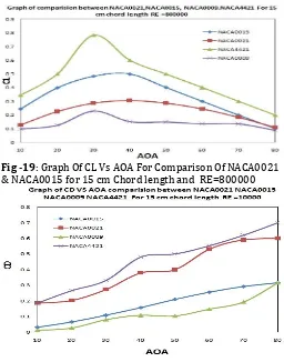
Fig -19: Graph Of CL Vs AOA For Comparison Of NACA0021 & NACA0015 for 15 cm Chord length and RE=800000
Fig -20: Graph Of CD Vs AOA For Comparison Of NACA0021 & NACA0015 for 15 cm Chord length and RE=10000
From fig 19 to fig 20 Comparison has been between four blade profile (NACA0021, NACA0015, NACA0009, NACA4421) for lift coefficient Vs angle of attack for same Reynolds number (like Ranging from 10000, 40000, 160000, 360000, and 800000) and same chord length for 15 cm, and it has been observed that among all Reynolds number NACA4421 shows highest lift coefficient 0.78 at angle of attack 300 at RE=8000000. And four blade profile
(NACA0021 NACA0015 NACA009 NACA4421) for drag coefficient Vs angle of attack for same Reynolds number (like Ranging from 10000, 40000, 160000, 360000, and 800000) and same chord length for 5 cm, and it has been observed that among all Reynolds number NACA4421 shows highest drag coefficient =0.7 at angle of attack 800 and for RE=10000
for 10 cm chord length
[image:6.595.312.539.184.351.2]7.EXPERIMENTAL RESULTS FOR OPTIMUM DESIGN
Fig -21: Graph Of CL Vs AOA For Comparison Of NACA4421 for 15 cm Chord length and RE=800000
Fig -22: Graph Of CD Vs AOA For Comparison Of NACA4421 for 15 cm Chord length and RE=800000
From fig 21 to fig 22 Comparison has been between four blade profile (NACA0021, NACA0015, NACA0009, NACA4421) for lift coefficient Vs angle of attack for same Reynolds number (like Ranging from 10000, 40000, 160000, 360000, and 800000) and same chord length for 10 cm, and it has been observed that among all Reynolds number NACA4421 shows highest lift coefficient 0.74 at angle of attack 300 at RE=800000. And four blade profile (NACA0021
NACA0015 NACA009 NACA4421) for drag coefficient Vs angle of attack for same Reynolds number (like Ranging from 10000, 40000, 160000, 360000, and 800000) and same chord length for 15 cm, and it has been observed that among all Reynolds number NACA4421 shows highest drag coefficient =0.21 at angle of attack 800 and for RE=800000
[image:6.595.308.540.389.529.2]© 2016, IRJET | Impact Factor value: 4.45 | ISO 9001:2008 Certified Journal | Page 2901
Fig -23:Graph Of CL Vs AOA For Comparison Of NACA4421for 15 cm Chord length for RE=800000 by Analytical & Experimental
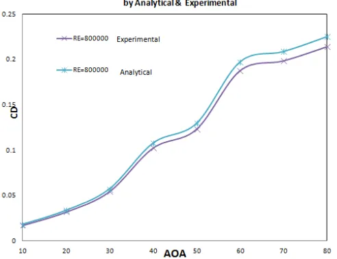
Fig -24:Graph Of CD Vs AOA For Comparison Of NACA4421 for 15 cm Chord length for RE=800000 by Analytical & Experimental
From fig 23 to fig 24 Comparison has been between four blade profile (NACA0021, NACA0015, NACA0009, NACA4421) for lift coefficient Vs angle of attack for same Reynolds number (like Ranging from 10000, 40000, 160000, 360000, and 800000) and same chord length for 10 cm, and it has been observed that among all Reynolds number NACA4421 shows highest lift coefficient 0.74(experimentally) & 0.78(analytically) at angle of attack 300 at RE=800000. And four blade profile (NACA0021
NACA0015 NACA009 NACA4421) for drag coefficient Vs angle of attack for same Reynolds number (like Ranging from 10000, 40000, 160000, 360000, and 800000) and same chord length for 15 cm, and it has been observed that among
all Reynolds number NACA4421 shows highest drag coefficient 0.21(experimentally) & 0.22(Analytically) at angle of attack 800 and for RE=800000 for 15 cm chord
length.
8. CONCLUSIONS
1. CFD analysis is carried out for four different blade profile (NACA0021 NACA0015 NACA0009 NACA4421) five different Reynolds number (Range from 10000, 40,000, 160000 360000, 800000) and eight different angles of attack 10o to 80o for three different chord
length ( i.e. 5 cm, 10 cm ,15 cm.)
2. So it observed that if Reynolds number increases lift coefficient increases with respect to increase in angle of attack, this happens due to increase in Reynolds number flow gets accelerated on upper surface of aerofoil and gets decelerated lower surface of aerofoil, so because of that pressure difference increases so lift coefficient increases.
3. It is also observed that for same chord length and same Reynolds number lift coefficient increase with increase in angle of attack and it reaches maximum value suddenly decreases, This phenomena called as stalling. 4. It has been seen that drag coefficient increase with increasing angle of attack and it reaches maximum value at angle of attack 800, in every case.
5. Comparison has been done between lift coefficient VS angle of attack and Drag coefficient VS angle of attack for same Reynolds number and three different chord lengths for four different blade profile NACA0021 NACA0015 NACA0009 NACA4421. So from all graphs it is observed that if we increase the chord length lift and drag coefficient increases. This happens due to if we increase the chord length Surface area around aerofoil increases, because of that lift increase.
6. After all comparisons between NACA0021 NACA0015 NACA0009 NACA4421 it has been found that NACA4421 with chord length 15 cm and Reynolds number RE=800000 shows highest lift coefficient 0.78( at angle of attack 300.
7. After CFD analysis NACA4421 with chord length 15 cm shows highest lift coefficient 0.78 (Analytically) & 0.74(experimentally) at angle of attack 300 and
RE=800000 among all chord length and all Reynolds number and all blade profile used.
8. So NACA4421 with chord length 15 cm shows highest Drag coefficient 0.22 (Analytically) & 0.21(experimentally) at angle of attack 800 and
RE=800000 among all chord length and all Reynolds number and all blade profile used.
REFERENCES
[image:7.595.39.285.381.570.2]© 2016, IRJET | Impact Factor value: 4.45 | ISO 9001:2008 Certified Journal | Page 2902
very Low Reynolds Numbers, Univ. of Notre Dame,Notre Dame, IN, pp. 184-196.
[2] Kunz P. J., Kroo I., (2000), “Analysis, design and testing of airfoils for use at ultra-low Reynolds numbers”. Proceedings of the Conference on Fised, Flapping and Rotary Vehicles at very Low Reynolds Numbers, Univ. of Notre Dame, Notre Dame, IN, pp. 349-372.
[3] Schmitz F. W. (1967) “Aerodyna:Zmics of the model airplane. Part I. Airfoil measurements”, NACA TM X-60976.
[4] Sheldahl R. E., Klimas P. C. “Aerodynamic characteristics of seven symmetrical airfoil sections through 180º angle of attack for use in aerodynamic analysis of vertical axis wind turbines”, Sandia national laboratories energy Report, SAND80-2114.
[5] Sunada S., Sakaguchi A., Kawachi K. (1997), “Airfoil section characteristics at a low Reynolds number”. Journal of Fluids Engineering, 119, pp. 129-135. [6] Sunada S., Yasuda T., Yasuda K., Kawachi K., (2002)
“Comparison of wing characteristics at an ultralow Reynolds number.” Journal of Aircraft, 39, pp. 331-338. [7] Nazmul Haque, Mohammad Ali, Ismat Ara, “Experimental investigation on the performance of NACA 4412 aerofoil with curved leading edge planform”, Procedia Engineering 105 ( 2015 ) pp. 232 – 240. [8] Md Farhad Ismail, Krishna Vijayaraghavan, “The effects
of aerofoil profile modification on a vertical axis wind turbine performance”, Energy 80 (2015) pp. 20-31. [9] J.M. Rainbird, J. Peiró, J.M.R. Graham, “Blockage-tolerant
wind tunnel measurements for a NACA 0012 at high angles of attack”, J. Wind Eng. Ind. Aerodyn. 145 (2015) pp. 209–218,
BIOGRAPHIES
Parashar S. S. borned in Manmad, situated in Maharashtra India in year 1992. She completed her high school education from St. Xavier's English Medium School in Manmad. She is graduated in Mechanical Engineering from S.N.D.C.O. Engineering and Research Center Yeola. Now persuing Master degree in Design branch from S.N.D.C.O. Engineering and Research Center yeola.
As her interest is towards design and development, she had shown her Skill in design field. She had done two project in Design field. The First project is ""Vibratory Super Finishing unit". This project was showcased in DIPEX- 2014.
Snehal has also Presented Paper on the topic"Stress Analysis & Optimazation of forged steel single cylinder engine connecting rod subjected to dynamic loading" in year 2015,
are organized by International Journal of Engineering, Education & Technology, India.
Prof. V.G. Bhamare received B.E. and M.E. (Thermal) degrees in mechanical engineering. He is pursuing Ph.D. degree in mechanical engineering from Nagpur University, Maharashtra, India.