TM
Quasi-Euclidean Recovery from Unknown but Complete Orbital Motion
Sing Bing Kang
CRL 97/10
Cambridge Research Laboratory
The Cambridge Research Laboratory was founded in 1987 to advance the state of the art in both core computing and human-computer interaction, and to use the knowledge so gained to support the Company’s corporate objectives. We believe this is best accomplished through interconnected pur-suits in technology creation, advanced systems engineering, and business development. We are ac-tively investigating scalable computing; mobile computing; vision-based human and scene sensing; speech interaction; computer-animated synthetic persona; intelligent information appliances; and the capture, coding, storage, indexing, retrieval, decoding, and rendering of multimedia data. We recognize and embrace a technology creation model which is characterized by three major phases:
Freedom: The life blood of the Laboratory comes from the observations and imaginations of our
research staff. It is here that challenging research problems are uncovered (through discussions with customers, through interactions with others in the Corporation, through other professional interac-tions, through reading, and the like) or that new ideas are born. For any such problem or idea, this phase culminates in the nucleation of a project team around a well articulated central research question and the outlining of a research plan.
Focus: Once a team is formed, we aggressively pursue the creation of new technology based on
the plan. This may involve direct collaboration with other technical professionals inside and outside the Corporation. This phase culminates in the demonstrable creation of new technology which may take any of a number of forms - a journal article, a technical talk, a working prototype, a patent application, or some combination of these. The research team is typically augmented with other resident professionals—engineering and business development—who work as integral members of the core team to prepare preliminary plans for how best to leverage this new knowledge, either through internal transfer of technology or through other means.
Follow-through: We actively pursue taking the best technologies to the marketplace. For those
opportunities which are not immediately transferred internally and where the team has identified a significant opportunity, the business development and engineering staff will lead early-stage com-mercial development, often in conjunction with members of the research staff. While the value to the Corporation of taking these new ideas to the market is clear, it also has a significant positive im-pact on our future research work by providing the means to understand intimately the problems and opportunities in the market and to more fully exercise our ideas and concepts in real-world settings.
Throughout this process, communicating our understanding is a critical part of what we do, and participating in the larger technical community—through the publication of refereed journal articles and the presentation of our ideas at conferences–is essential. Our technical report series supports and facilitates broad and early dissemination of our work. We welcome your feedback on its effec-tiveness.
Quasi-Euclidean Recovery from Unknown but Complete Orbital
Motion
Sing Bing Kang
October 1997
Abstract
c Digital Equipment Corporation, 1997
This work may not be copied or reproduced in whole or in part for any commercial purpose. Per-mission to copy in whole or in part without payment of fee is granted for nonprofit educational and research purposes provided that all such whole or partial copies include the following: a notice that such copying is by permission of the Cambridge Research Laboratory of Digital Equipment Corpo-ration in Cambridge, Massachusetts; an acknowledgment of the authors and individual contributors to the work; and all applicable portions of the copyright notice. Copying, reproducing, or repub-lishing for any other purpose shall require a license with payment of fee to the Cambridge Research Laboratory. All rights reserved.
CRL Technical reports are available on the CRL’s web page at http://www.crl.research.digital.com.
Digital Equipment Corporation Cambridge Research Laboratory One Kendall Square, Building 700
CONTENTS i
Contents
1 Introduction 1
1.1 Prior work . . . 1 1.2 Quasi-Euclidean reconstruction from unknown but complete orbital motion . . . . 3 1.3 Organization . . . 4
2 General structure from motion 4
2.1 Least-squares minimization . . . 5 2.2 Two-stage approach . . . 6 2.3 Initialization . . . 6
3 Tracking 7
4 Sensitivity of reconstruction to tilt 8
5 Results 9
5.1 Sequence of rotating synthetic cylindrical object . . . 9 5.2 Sequences of rotating real objects . . . 9 5.3 Complete rotation vs. incomplete rotation . . . 11
6 Discussion 12
ii LIST OF FIGURES
List of Figures
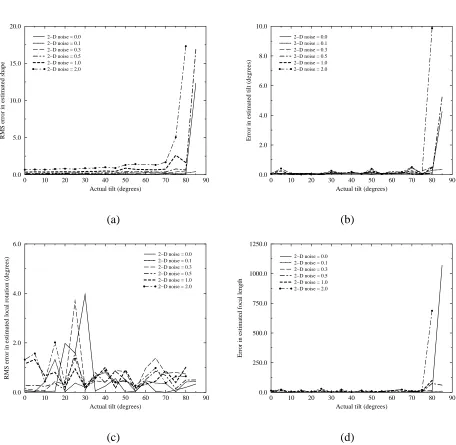
1 Graphs illustrating sensitivity of recovered (a) shape, (b) tilt angle, (c) local rota-tion angle, and (d) focal length, to the actual camera tilt during complete orbital motion. See text for a description of the conditions to which the experiments were subject. . . 10 2 Rotating synthetic cylinder (complete rotation, 40 frames): (a) 1st frame, (b) 5th
frame, (c) top view, and (d) side view of recovered 3-D points (2291 points). . . 11 3 Rotating film box (complete rotation, 31 frames): (a) 1st frame, (b) 5th frame, (c)
point tracks, (d)-(e) top, and side views of recovered 3-D points (1414 points). . . . 12 4 Rotating film box (complete rotation, 31 frames): (a) 1st frame, (b) 5th frame, (c)
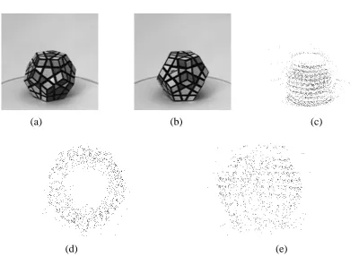
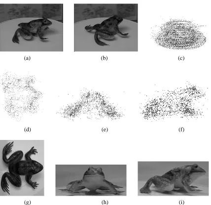
point tracks, (d)-(f) top, front, and side views of recovered 3-D points (1414 points). 13 5 Rotating toy frog (complete rotation, 43 frames): (a) 1st frame, (b) 5th frame, (c)
2260 point tracks, (d)-(f) top, front, and side views of recovered 3-D points, (g)-(i) corresponding views of the actual toy frog. . . 14 6 Rotating cube (complete rotation, 48 frames): (a) first frame, (b) top view of
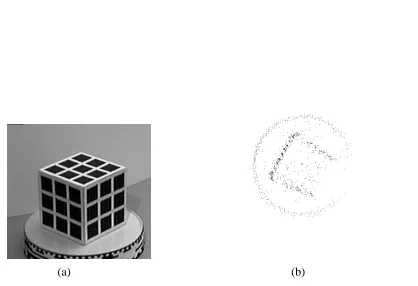
re-covered 3-D points (2500 points), (c) side view of 3-D points. . . 15 7 Rotating cube (not complete rotation): (a) First frame of the sequence, and (b) Top
view of recovered points for the cube scene using 96 frames and known camera parameters. (From [25].) Notice the pinching effect. . . 15 8 Rotating synthetic cube: (a) Reconstruction from complete rotation, (b)
1
1
Introduction
In this technical report, we address the problem of quasi-Euclidean reconstruction using an un-calibrated camera with the specific known type of motion, namely unknown but complete orbital
motion. By orbital motion, we mean pure rotation about a fixed arbitrary axis. Exact scaled
Euclidean reconstruction for orbital motion is not possible because of the 2 degree-of-freedom ambiguity [22]. We bypass the usual intermediate stages of projective or affine reconstruction and recover direct 3-D structure from point correspondences. The feature point correspondence are ob-tained from a two-stage bidirectional tracking process. 3-D reconstruction is done by applying the iterative Levenberg-Marquardt algorithm to minimize error between actual point tracks and pro-jected point tracks. Initialization is based on estimating the tilt by fitting ellipses on point tracks and assuming equal angular rotation between frames. Convergence is speeded up by adopting an object-centered representation. This work is an extension of [25] with the projection function hav-ing the option of ushav-ing all five camera intrinsic parameters (focal length
f
, aspect ratior
, image skew , and principal point(
u0v0
)
). We also demonstrate that results from complete orbital mo-tion are superior to those of partial orbital momo-tion. This work also investigates the sensitivity of quasi-Euclidean reconstruction to the actual camera tilt during orbital motion.1.1
Prior work
There is a large body of work done on 3-D reconstruction from images using an uncalibrated camera. One of the first steps taken prior to actual 3-D reconstruction is usually the process of camera calibration. Particularly germane to 3-D reconstruction using an uncalibrated camera is
self-calibration. Self-calibration refers to recovery of camera parameters based only on
corre-spondences of images taken at different poses. Most work done on self-calibration rely on known motions of the cameras, such as pure translational motion [2], known camera rotation angles [3], rotation about an unknown but fixed arbitrary axis [25], and pure rotation about the camera center [7].
2 1 INTRODUCTION
the object is recovered from silhouettes. Zhang [26] proposes a closed-form solution for scaled Euclidean reconstruction with known intrinsic camera parameters but unknown extrinsic camera parameters. However, this technique assumes the existence of four coplanar correspondences that are not collinear.
Recently, however, there has been interesting work done in reconstructing scaled Euclidean structure from images using an uncalibrated camera. In a work that is probably the closest to ours, Heyden and Astrom [9] propose a technique to reconstruct scaled Euclidean structure under con-stant but unknown intrinsic camera parameters. They showed that in general, it takes a minimum of 3 images to recover a unique solution to the intrinsic camera parameters and scaled Euclidean structure. This is done by considering the Kruppa constraints [13, 15]. Their technique of scaled Euclidean reconstruction is based on recovering an intermediate projective structure. They then use an optimization formulation that is based on the Frobenius norm of a matrix. However, this is not equivalent to the more optimal metric of minimizing feature location errors in the 2-D image space. In a later work, they also show that scaled Euclidean reconstruction under known image as-pect ratio and skew but varying and unknown focal length and principal point is also possible [10]. The assumption is that the camera is undergoing general motion, as it is not possible to reconstruct scaled Euclidean structure under constrained motion such as pure translational or orbital motion.
A two-step approach is used to recover scaled Euclidean structure from multiple image se-quences with unknown but constant intrinsic parameters [18]. The first stage involves affine cam-era parameter recovery using the so-called modulus constraint. This is followed by conversion to scaled Euclidean structure. This approach is subsequently extended to remove the assumption of fixed camera focal length [17].
Hartley devises an algorithm for camera self-calibration from several views [5]. He uses a two-step approach to recover scaled Euclidean structure. His algorithm first recovers projective structure before applying a heuristic to search for extract the five intrinsic camera parameters. The heuristic involves iterating over several sets of initialization values and checking for convergence.
1.2 Quasi-Euclidean reconstruction from unknown but complete orbital motion 3
1.2
Quasi-Euclidean reconstruction from unknown but complete orbital
mo-tion
As Sturm as demonstrated [22], there exists a 2 degree-of-freedom ambiguity in scaled Euclidean reconstruction. There are three options in recovering scaled Euclidean structure from orbital mo-tion: (1) fix two intrinsic camera parameters, (2) impose structural constraints (e.g., orthogonality, parallelism, known 3-D locations of fiducial points), or (3) get the “best” reconstruction without (1) or (2). We choose to option (3), though option (1) is another convenient option as well. In particular, for option (1), we can assume that the aspect ratio
r
to be 1.0 and the image skew to be 0. In practice, these parameters are usually fixed for a camera and need to be determined only once.We recover 3-D structure and orbital motion from relatively sparse sequence of images (typ-ically between 30-50 images in a sequence). The unknowns are the camera intrinsic parameters, global camera tilt, local rotation axis, amount of local rotation between successive frames, and the 3-D positions associated with the tracked point features.
The assumptions that we have made for our work are the following:
The image sequence is a “closed loop” sequence (i.e., featuring complete object rotation),
The object surface has sufficient texture for interframe feature tracking,
The object rotation is about an unknown but fixed axis, and
The camera either does not have significant radial distortion, or the radial distortion factor is known so that the images can be corrected first.
The advantages of using our approach of recovering structure and motion from complete object rotation (or equivalently, complete camera orbital motion):
The set-up is extremely simple and cheap (using a camera, tripod stand, and a turntable would do),
The global tilt angle, local rotation angles, and quasi-Euclidean structure can be extracted simultaneously,
Calibration of camera is not required,
4 2 GENERAL STRUCTURE FROM MOTION
Recovery of the intermediate affine or projective structure is not necessary, and
The method exhibits fast convergence and is stable.
1.3
Organization
In Section 2, we outline the general structure from motion problem and our approach to recov-ering the solution specifically in the special case of unknown but complete orbital motion. The bidirectional tracking scheme employed to recover the point tracks for a given image sequences is described in Section 3. One of the important parameter in orbital motion is the amount of camera tilt. Section 4 shows, through simulations, how sensitive recovered shape and camera parameters are to the actual camera tilt. The results of reconstruction using image sequences of rotated sim-ulated and real objects are given in Section 5. This section also illustrates the improvement in results due to the knowledge of complete camera orbital motion (or object rotation). The method and its results are discussed in Sections 6; finally, a summary of the method and its implications are presented in Section 7 respectively.
2
General structure from motion
The formulation of recovering structure from motion is based on that of [25]. Essentially, we are trying to recover a set of 3-D structure parameters
p
iand time-varying motion parametersT
j from
a set of observed image features
u
ij. The general equation linking a 2D image feature locationu
ijin frame
j
to its 3-D positionp
i (i
is the track index) isu
ij=
P
T
(K)
j
:::T
(1) jp
i (1)where the perspective projection transformationP
()
is applied to a cascaded series of rigidtrans-formation
T
(k) j. Each transformation is in turn defined by
T
(k)j
x
=
R
(k)
j
x
+
t
(k)
j (2)
where
R
(k) is a rotation matrix andt
(k)
j
is a translation applied after the rotation.
Within each of the cascaded transforms, the motion parameters may be time-varying (the
j
subscript is present) or fixed (the subscript is dropped). The transformation associated with the (horizontal) orbital motion that we are considering in our work isu
ij=
P
(
R
2.1 Least-squares minimization 5
where
R
xR
zrepresent rotation about the x-axis by and z-axis by respectively. We assumenegligible cyclotorsion (rotation of camera about the viewing axis). The general camera-centered perspective projection equation is
0 @
u
v
1 A=
P1 0 B B @x
y
z
1 C C A 0 @fx+y
z
+
u0
rfy
z
+
v0
1
A (4)
where
f
is a product of the focal length of the camera and the pixel array scale factor,r
is the image aspect ratio, is the image skew, and(
u0v0
)
is the principal point.An alternative object-centered formulation (a more general version of [25]) which we use is
0 @
u
v
1 A=
P2 0 B B @x
y
z
1 C C A 0 @sx+y
1+z
+
u0
rsy
1+z
+
v0
1
A (5)
Here, we assume that the
(
xyz
)
coordinates before projection are with respect to a reference frame that has been displaced away from the camera by a distancet
z along the optical axis,1with
s
=
f=t
z and= 1
=t
z. The projection parameters
can be interpreted as a scale factor andas a perspective distortion factor. Our alternative perspective formulation results in a more robust recovery of camera parameters under weak perspective, where
1
, and assuming(
u0v0
)
(0
0)
and0
, we haveP(
xyz
)
T
(
sxrsy
)
T. This is because
s
andrs
can be much more reliably recovered than, in comparison with the old formulation wheref
andt
z are very highlycorrelated.
2.1
Least-squares minimization
The Levenberg-Marquardt algorithm [19] is used to solve for the structure and motion parameters. The merit or objective function that we minimize is
C
(
a
) =
X i X j
c
ij ju
ij;
f
(
a
ij
)
j
2
(6)
where
f
()
is given in (1) anda
ij=
p
Ti
m
T
j
m
T g
T
(7)
1If we wish, we can view
t z as the
z component of the original global translation which is absorbed into the
6 2 GENERAL STRUCTURE FROM MOTION
is the vector of structure and motion parameters which determine the image of point
i
in framej
. The vectora
contains all of the unknown structure and motion parameters, including the 3-D pointsp
i, the time-dependent motion parametersm
j, and the global motion/calibration parametersm
g. The weightc
ij in (6) describes our confidence in measurementu
ij, and is normally set to theinverse variance ;2
ij . Implementational details are given in [25]. The primary difference between
their work and this work is that we incorporate the additional camera intrinsic parameters
r
, ,u0, and
v0. The extensions (calculating the required derivatives of the Hessian matrix and gradient
vector) are relatively straightforward.
2.2
Two-stage approach
As Sturm has shown [22], there is a 2 degree-of-freedom ambiguity in scaled Euclidean reconstruc-tion for orbital moreconstruc-tion. A simple solureconstruc-tion to this is to set two of the intrinsic camera parameters to a constant (either as an assumption or through calibration). A good choice would be to fix the image skew factor (say to 0) and the aspect ratio
r
(say to 1). However, in our work, we keep these parameters unknown.We use a two-step approach in acquiring the quasi-Euclidean structure:
Fix
=
u0
=
v0
= 0
andr
= 1
and apply the Levenberg-Marquardt algorithm until ter-minating conditions are met. The termination conditions are either the number of iterations exceeds a threshold (150 in our case) or the improvement in the objective function is too small (10
;6 in our case), whichever comes first.Set
u0v0, and
r
to be free variables and resume with Levenberg-Marquardt algorithm (with the iteration number reset to 0) until the same termination conditions are again met.In general, using this two-step approach has resulted in better convergence towards lower image projection errors and better structure and motion recovery in comparison to not applying the first step. This observation is based on more than 100 runs that involve synthetic image sequences and about 6 runs involving real image sequences.
2.3
Initialization
7
360 j
Nframe
. The camera tilt is estimated by fitting ellipses to the tracks. The estimated tilt used for initialization is usually within 15
of the actual camera tilt (based on simulation results).
The scale factor
s
and perspective distortion factorare initialized to arbitrary values of 1.0 and 0.001 respectively. The algorithm does not appear to be too sensitive to these values, as changes up to about an order of magnitude is tolerated.3
Tracking
To produce tracks in a circular sequence as input to the iterative least-squares minimizing proce-dure, we first mask out regions that do not change significantly in intensity through simple pairwise image subtraction. This is effective in removing the static background and low object texture areas.
The tracking then proceeds by way of bidirectional tracking with three stages:
1. Pairwise global spline-based registration [24],
2. Automatic selection of spline node points with high local texture,
3. Multiframe Shi-Tomasi local tracking [21] of these spline nodes.
These three stages are necessary to incorporate the advantages of both spline-based registration and local tracking techniques. While the spline-based registration technique is able to track relatively significant motion, it is not able to deal with motion discontinuity very well due to its implicit smoothness constraint. On the other hand, the local tracking technique performs very poorly for significant motion but very well within the vicinity of the true track position. Because points are tracked independently for local tracking, motion discontinuities can be handled. Since the spline-based registration technique yields a reasonably good estimate of motion, the local tracking technique can then make use of this estimate to improve on the new track image position, especially if the position is within the vicinity of a motion discontinuity.
In the first stage, image flow between successive frames in the circular sequence is computed in both directions using the spline-based registration technique. Then, in stage 2, for each frame, points with high local texture (indicated by the minimum eigenvalue of the local Hessian) are automatically chosen for tracking. Finally, at the third and final stage of tracking, for every frame, the chosen points are then individually locally tracked in both directions using the flow estimates from stage 1. The tracking stops (tracking in the two directions is independent) if any of the following conditions is violated:
8 4 SENSITIVITY OF RECONSTRUCTION TO TILT
The RMS pixel difference error is less than a threshold (15 in our case), or
The minimum eigenvalue is above a threshold (500 in our case).
The problem with the first criterion above is that a complete track that is observable in all the frames is not possible. However, the need to reject random noise is greater, and having a few more redundant points is a relatively small price to pay. The tracks are postprocessed to remove those that are deemed too short (we impose a minimum track length of 3).
4
Sensitivity of reconstruction to tilt
To ensure that the ground truth is available, experiments were conducted using a collection of synthetic 3-D points. The 3-D points were generated at random, and the only constraint on their location is that they have to be within a radius of 25 from its local center. The object local center is chosen to be a distance of 225 from the camera center. Each 3-D point is oriented, i.e., each point has a normal associated with it. This allows “visibility” to be determined based on the camera pose; a point
p
i with normaln
^
i is visible under camera posej
ifn
^
i^
z
j
cam
0
.^
z
j
cam
is thej
th unit camera viewing direction away from the camera. Tracking is not explicitly done here, since we can calculate the 2-D image coordinates directly based on known camera and object transformations. Structure from orbital motion is then performed on the artificial tracks, with different image (Gaussian) noise levels.The RMS error in recovered 3-D is calculated by finding
E
= min
NpointsX
i=1
jj
p
icor
;
m
Rp
i
;
c
jj2 (8)
and taking the square root ofE.
Npoints is the number of points, and
p
icor and
p
i the theoreticallycorrect and recovered
i
th point respectively.m
is the global scale,R
the global rotation, andc
the global translation; these parameters constitute the best rigid body transformation between the theoretically correct and recovered set of points. We implemented Horn’s algorithm that uses a closed-form solution for this least-squares problem [11]. An alternative method that can be used is based on singular value decomposition (SVD) of a 33 matrix [1].We ran experiments involving a variety of gaussian image noise, namely, 0.0, 0.1, 0.3, 0.5, 1.0, and 2.0 pixels. As a reference, the projected 3-D points are distributed within an area of approximately 6060 pixels. The results of the experiment are graphically shown in Figure 1. For
9
of reference for the graph shown in Figure 1(a), the 3-D points are randomly distributed within a ball of radius of 25, and the center of this ball is a distance of 225 away from the center of the camera. The actual focal length is 324.
As can be seen in Figure 1, the error in recovered shape and tilt generally increases with the camera tilt. There are two surprises: (1) the very gradual increase in error followed by a very sharp increase in error with increasing actual camera tilt, and (2) the error in the local rotation angle estimate does not seem to exhibit a consistent trend. The sharpness of the reciprocal trend in (1) is somewhat attenuated by noise, as shown in Figure 1(a).
5
Results
In this section, we present results using a synthetic object as well as several real objects. In addi-tion, we compare results obtained from complete rotation with those from the exact same sequence, but without the completeness of rotation assumption. The initialization is the same for both cases.
5.1
Sequence of rotating synthetic cylindrical object
In the previous synthetic examples, the tracks were computed directly from known camera param-eters. In this example, however, a textured cylinder was defined, rotated, and then rendered using Rayshade. (Rayshade is a program for producing ray-traced color images [12].) The sequence of images produced in this manner is then treated as a normal input sequence whose bidirectional point tracks are recovered and fed into the “structure from complete orbital motion” module. The camera tilt is maintained at
0
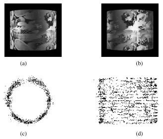
, and there are 40 frames in this sequence (two of which are shown in Figure 2(a) and (b). Two views of the reconstructed 3-D points are shown in Figure 2(c) and (d). The average (best-fit) cross-sectional radius of the recovered points is 0.823869, while the RMS error of the fit in radius is 0.063680. Since the actual radius of cylinder is 1.0, the rescaled RMS error of radius fit is 0.077293842. Because the distance of the cylinder from the camera is 8.0, the rescaled RMS error of radius fit of the recovered set of 3-D points constitute only about 1% of the camera distance.
5.2
Sequences of rotating real objects
10 5 RESULTS
0 10 20 30 40 50 60 70 80 90
Actual tilt (degrees) 0.0
5.0 10.0 15.0 20.0
RMS error in estimated shape
2−D noise = 0.0 2−D noise = 0.1 2−D noise = 0.3 2−D noise = 0.5 2−D noise = 1.0 2−D noise = 2.0
0 10 20 30 40 50 60 70 80 90
Actual tilt (degrees) 0.0 2.0 4.0 6.0 8.0 10.0
Error in estimated tilt (degrees)
2−D noise = 0.0 2−D noise = 0.1 2−D noise = 0.3 2−D noise = 0.5 2−D noise = 1.0 2−D noise = 2.0
(a) (b)
0 10 20 30 40 50 60 70 80 90
Actual tilt (degrees) 0.0
2.0 4.0 6.0
RMS error in estimated local rotation (degrees)
2−D noise = 0.0 2−D noise = 0.1 2−D noise = 0.3 2−D noise = 0.5 2−D noise = 1.0 2−D noise = 2.0
0 10 20 30 40 50 60 70 80 90
Actual tilt (degrees) 0.0 250.0 500.0 750.0 1000.0 1250.0
Error in estimated focal length
2−D noise = 0.0 2−D noise = 0.1 2−D noise = 0.3 2−D noise = 0.5 2−D noise = 1.0 2−D noise = 2.0
[image:16.612.74.530.141.586.2](c) (d)
5.3 Complete rotation vs. incomplete rotation 11
(a) (b)
[image:17.612.140.469.102.383.2](c) (d)
Figure 2: Rotating synthetic cylinder (complete rotation, 40 frames): (a) 1st frame, (b) 5th frame, (c) top view, and (d) side view of recovered 3-D points (2291 points).
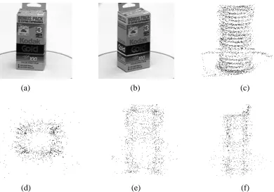
As can be seen, the 3-D points for all these sequences have been recovered reasonably well. The film box was the most difficult sequence, since the surface of the box is highly specular. This resulted in noisier D position estimates (Figure 4). In addition, it can be observed from Figures 3-5 that the point traces are not all correct. Outlier rejection was used in the Levenberg-Marquardt to remove points that may be wrongly tracked.
5.3
Complete rotation vs. incomplete rotation
12 6 DISCUSSION
(a) (b) (c)
[image:18.612.108.508.94.380.2](d) (e)
Figure 3: Rotating film box (complete rotation, 31 frames): (a) 1st frame, (b) 5th frame, (c) point tracks, (d)-(e) top, and side views of recovered 3-D points (1414 points).
(Figure 6) do not result in the same “pinched” appearance.
Another example is shown in Figure 8. Figure 8(a) shows the top view of the reconstructed 3-D points for the case when complete rotation is assumed, while Figure 8(b) shows the same points for the case when complete rotation is not assumed. In this case, each track that spans across the first and last frames is first broken up into two shorter tracks. The longer of the two fragmented tracks is used while the other is discarded. Not surprisingly, the reconstructed 3-D points for the complete rotation case is better. There are 416 points on the cube, and the camera tilt is 45
for both cases. The tracks were synthetically generated with no noise, and there were 45 frames with equiangularly spaced object rotation. Initialization for both cases is exactly the same.
6
Discussion
13
(a) (b) (c)
[image:19.612.112.502.105.378.2](d) (e) (f)
Figure 4: Rotating film box (complete rotation, 31 frames): (a) 1st frame, (b) 5th frame, (c) point tracks, (d)-(f) top, front, and side views of recovered 3-D points (1414 points).
practice, the camera intrinsic parameters of principal point
(
u0v0
)
, image skew , and aspect ratior
do not usually deviate significantly from normally assumed values of (0, 0), 0, and 1 respec-tively. We operate based on our preference of maximizing knowledge of the camera to directly reconstructing 3-D shape, rather than converting to intermediate projective or affine representa-tions.Results of experiments with simulated tracks having varying degrees of image feature location noise and actual camera tilt (relative to the vertical axis) were generally expected, with some surprises. While errors in estimated reconstructed shape, camera tilt, and focal length increased with actual camera tilt, the rate of increase in these errors is unexpected. The rate of increase in error is generally gradual up until angles close to 90
14 6 DISCUSSION
(a) (b) (c)
(d) (e) (f)
[image:20.612.93.521.155.571.2](g) (h) (i)
15
[image:21.612.87.529.140.271.2](a) (b) (c)
Figure 6: Rotating cube (complete rotation, 48 frames): (a) first frame, (b) top view of recovered 3-D points (2500 points), (c) side view of 3-D points.
(a) (b)
[image:21.612.87.505.315.601.2]16 7 SUMMARY
[image:22.612.131.481.89.274.2](a) (b)
Figure 8: Rotating synthetic cube: (a) Reconstruction from complete rotation, (b) Reconstruction from incomplete rotation.
Finally, not surprisingly, results for experiments with the assumption that the object rotation (or equivalently, camera orbital motion) spans a full 360
are better than those with no such assump-tion. The better results are due to the addition constraints available in connection with the point tracks that bridges the first and last frames of the (circular) image sequence. One can anticipate that in the general case, structure and motion recovery from arbitrary but “closed loop” motion of the camera would be more accurate than if there is no assumption of direct connectedness between the first and last frames of the image sequence.
7
Summary
We have described a completely automatic method of recovering quasi-Euclidean structure from unknown by complete object rotation (or equivalently, camera orbital motion). This method starts with two-stage bidirectional tracking, followed by the application of iterative Levenberg-Marquardt minimization of feature point error to recover structure and rotational motion simulta-neously. Apart from the knowledge that the object was rotated completely about a unique axis, no other camera parameters are assumed known.
REFERENCES 17
the recovered tracks.
Simulations have indicated the surprising result that the recovered errors in shape, tilt, and focal length exhibit a very sharp reciprocal relationship with respect to the actual camera tilt. The sharpness is attenuated by 2-D feature location (gaussian) noise. Another interesting result of the same simulations is the relative indifference of errors in recovered local rotation angles to both actual camera tilt and noise. Applying the technique on image sequences of real rotated objects has yielded very reasonable-looking results of recovered 3-D object feature distribution.
References
[1] K.S. Arun, T.S. Huang, and S.D. Blostein. Least-squares fitting of two 3-D point sets. IEEE
Transactions on Pattern Analysis and Machine Intelligence, 9(5):698–700, September 1987.
[2] L. Dron. Dynamic camera self-calibration from controlled motion sequences. In IEEE
Com-puter Society Conference on ComCom-puter Vision and Pattern Recognition (CVPR’93), pages
501–506, New York, NY, June 1993. IEEE Computer Society Press.
[3] F. Du and M. Brady. Self-calibration of the intrinsic parameters of cameras for active vision systems. In IEEE Computer Society Conference on Computer Vision and Pattern Recognition
(CVPR’93), pages 477–482, New York, NY, June 1993. IEEE Computer Society Press.
[4] O. D. Faugeras. What can be seen in three dimensions with an uncalibrated stereo rig? In
Sec-ond European Conference on Computer Vision (ECCV’92), pages 563–578, Santa Margherita
Liguere, Italy, May 1992. Springer-Verlag.
[5] R. I. Hartley. An algorithm for self calibration from several views. In IEEE Computer Society
Conference on Computer Vision and Pattern Recognition (CVPR’94), pages 908–912, Seattle,
Washington, June 1994. IEEE Computer Society.
[6] R. I. Hartley. Projective reconstruction and invariants from multiple images. IEEE
Transac-tions on Pattern Analysis and Machine Intelligence, 16(10):1036–1041, October 1994.
[7] R. I. Hartley. Self-calibration from multiple views with a rotating camera. In Third European
Conference on Computer Vision (ECCV’94), volume 1, pages 471–478, Stockholm, Sweden,
18 REFERENCES
[8] A. Heyden. Reconstruction from image sequences by means of relative depths. In Fifth
In-ternational Conference on Computer Vision (ICCV’95), pages 1058–1063, Cambridge,
Mas-sachusetts, June 1995. IEEE Computer Society Press.
[9] A. Heyden and K. Astrom. Euclidean reconstruction from constant intrinsic parameters. In
Proc.s 13th International Conference on Pattern Recognition, pages 339–343, 1996.
[10] A. Heyden and K. Astrom. Euclidean reconstruction from image sequences with varying and unknown focal length and principal point. In Proc.s IEEE Computer Society Conference on
Computer Vision and Pattern Recognition, pages 438–443, June 1997.
[11] B. K. P. Horn. Closed-form solution of absolute orientation using unit quaternions. Journal
of the Optical Society of America A, 4(4):629–642, 1987.
[12] C. E. Kolb. Rayshade User’s Guide and Reference Manual, August 1994.
[13] E. Kruppa. Objektes aus zwei perspektiven mit innerer orientierung. Sitz.-Ber. Akad. Wiss.,
Math. Naturw. Kl., Abt. Ila., 122:1939–1948, 1913.
[14] Y. Matsumoto, H. Terasaki, K. Sugimoto, and T. Arakawa. A portable three-dimensional dig-itizer. In International Conference on Recent Advances in 3-D Digital Imaging and Modeling, pages 197–204, Ottawa, Canada, May 1997.
[15] S. Maybank. Theory of Reconstruction from Image Motion. Springer-Verlag, Berlin, 1993.
[16] W. Niem and J. Wingberm¨uhle. Automatic reconstuction of 3D objects using a mobile mono-scopic camera. In International Conference on Recent Advances in 3-D Digital Imaging and
Modeling, pages 173–180, Ottawa, Canada, May 1997.
[17] M. Pollefeys, L. Van Gool, and A. Oosterlinck. Euclidean reconstruction from image se-quences with variable focal length. In Fourth European Conference on Computer Vision
(ECCV’96), volume 1, pages 31–44, Cambridge, England, April 1996. Springer-Verlag.
[18] M. Pollefeys, L. Van Gool, and A. Oosterlinck. The modulus constraint: A new constraint for self-calibration. In Proc.s 13th International Conference on Pattern Recognition, volume 1, pages 349–353, 1996.
[19] W. H. Press, B. P. Flannery, S. A. Teukolsky, and W. T. Vetterling. Numerical Recipes in C:
The Art of Scientific Computing. Cambridge University Press, Cambridge, England, second
REFERENCES 19
[20] A. Shashua. Projective structure from uncalibrated images: Structure from motion and recog-nition. IEEE Transactions on Pattern Analysis and Machine Intelligence, 16(8):778–790, August 1994.
[21] J. Shi and C. Tomasi. Good features to track. In IEEE Computer Society Conference on
Computer Vision and Pattern Recognition (CVPR’94), pages 593–600, Seattle, Washington,
June 1994. IEEE Computer Society.
[22] P. Sturm. Critical motion sequences for monocular self-calibration and uncalibrated Eu-clidean reconstruction. In IEEE Computer Society Conference on Computer Vision and
Pat-tern Recognition (CVPR’97), pages 1100–1105, Puerto Rico, June 1997. IEEE Computer
Society.
[23] R. Szeliski. Shape from rotation. In IEEE Computer Society Conference on Computer
Vi-sion and Pattern Recognition (CVPR’91), pages 625–630, Maui, Hawaii, June 1991. IEEE
Computer Society Press.
[24] R. Szeliski and J. Coughlan. Hierarchical spline-based image registration. In IEEE Computer
Society Conference on Computer Vision and Pattern Recognition (CVPR’94), pages 194–201,
Seattle, Washington, June 1994. IEEE Computer Society.
[25] R. Szeliski and S. B. Kang. Recovering 3D shape and motion from image streams using non-linear least squares. Journal of Visual Communication and Image Representation, 5(1):10–28, March 1994.
TM
Quasi-Euc
lidean
Reco
ver
y
fr
o
m
Unkno
wn
b
u
t
Complete
Orbital
Motion
Sing
Bing
Kang
CRL
97/10
October