ISSN: 1992-8645 www.jatit.org E-ISSN: 1817-3195
434
ANALYSIS STUDY OF A CASCADED H-BRIDGE
MULTI-LEVEL INVERTER DEDICATED TO POWER BANK USAGE
1
TAJEDDINE KHALILI, 1ABDELHADI RAIHANI, 1OMAR BOUATTAN, 1HASSAN OUAJJI,
1FOUAD AMRI.
1
SSDIA Lab, ENSET Mohammedia, HASSAN II University of Casablanca, Morocco.
E-mail: [email protected]
ABSTRACT
Multi-level inverters have proved their efficiency for usage in variety of renewable energy applications. Therefore Converting DC voltage in a power bank containing multiple units using directly a multilevel inverter is a very powerful converting method. In this paper we present an analysis study of the cascaded H-bridge inverter in different conditions and different states namely 5, 9, and 17 levels. The architecture used trough the entire study is the same topology, the same command type was applied for all the models (SPWM). The study focuses on the output voltage quality and the efficiency of the power conversion. The study also discusses the influence of the unbalanced units state of charge inside the power bank on quality of the output voltage and present the most efficient level state configuration in both cases balanced and unbalanced.
Keywords: Multilevel Inverter, Cascaded H-bridge, SPWM, Unbalanced DC, THD.
1. INTRODUCTION
Multilevel inverters developed and studied recently, have shown a great reliability and better efficiency compared to classic DC/AC converters [1- 4]. Their development has been marked by the progress of semiconductor material technology and the development of digital signal processing. There are three basic multilevel inverters topologies the flying capacitor multilevel inverter FCMLI, the diode clamped multilevel inverter DCMLI and the cascaded H-bridge multilevel inverter [5- 10]. The CHMLI is the most suitable multilevel inverter for use with power banks containing multiple DC storage units. This multilevel inverter produces the best voltage output quality compared to the other architectures. The CHMLI is easy to command when looking to upgrade the numbers of levels. This study presents a comparative study of this same multilevel inverter in different states, levels and DC sources conditions. Thus we discuss the effect of unbalanced DC storage unit’s state of charge on the output power quality. The study presents an analysis of the cascaded H-bridge multilevel inverter in 5 levels, 9 levels and 17 levels conditions. In both balanced and unbalanced DC sources we used the same command (SPWM) [11-13]. An evaluation of the effect of the multilevel inverter level state in both balanced and unbalanced conditions is also presented.
2. THE BASIC CIRCUIT STUDY
2.1 CHMLI architecture
In order to simulate the effect of the power bank we set up multiple batteries in Matlab simulink. Each multilevel inverter uses sources simulated inside the power bank model depending on the number of levels. Figure 1 presents the model principle for the simulation of 3 levels H-Bridge inverter.
[image:1.612.315.525.498.617.2]The CHMLI uses the batteries inside the power bank as DC sources to synthesize a stair wave voltages staged in several levels, creating the sinusoidal signal. This multilevel inverter is composed of multiple full bridge inverters blocks; each block contains four power switches, and the phase voltage is the sum of the output voltages of each individual full bridge. It is very important to
ISSN: 1992-8645 www.jatit.org E-ISSN: 1817-3195
435 notice that this multilevel inverter avoids the use of interlocking diodes or balancing capacitors, and offers a very easy platform to control the firing angles of different voltage levels [14-16]. In order to relate the level state ( ) to the architecture configuration we can use the following relation:
2 1 : 1
2 1 : 2
2.2 Law command and the power bank model
In order to work with unified conditions, we used trough our study the same law command (SPWM). This widely used command basically compares a reference signal V to a number of saw tooth carriers depending on the level we want to produce. Figure 2 illustrates the reference signal along with the saw tooth carriers.
For three phases the reference signals can be expressed as follows:
!" #$% &. . 3 !) #$% &. . * 2+3 , 4 !. #$% &. . * 4+3 , 5 Where A is the Magnitude, m the modulation index and f is the frequency. In our study we took:
A 10, m 0.6 and f )65 (6) In order to see the mutual influence of the CHMLI different configurations on the power bank and the DC storage units unbalance state of charge on the output voltage quality, we modeled the power bank out of a multitude of lead-acid batteries on Matlab Simulink having the following simulation characteristics:
• Nominal voltage: 12V • Rated capacity: 6.5 Ah
• Initial state of charge: 100% • Maximum capacity: 6.77 Ah • Fully charged voltage: 13.06 V • Nominal discharge current: 1.3 A
• Internal resistance: 0.02 Ω
3. STUDY OF THE CHMLI IN DIFFERENT
CONFGURATONS
3.1 CHMLI in 5 levels mode
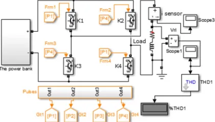
Figure 3 illustrates the architecture of the 5 levels cascaded H-bridge multilevel inverter used in Matlab simulink.
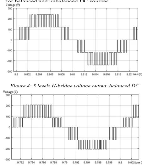
In this configuration we used two full bridge sections. The power bank was divided into two parts in order to simulate the functioning of the CHMLI in both balanced and unbalanced DC sources. Figure4 and 5 illustrates the voltage output for balanced and unbalanced DC sources.
[image:2.612.312.525.185.314.2]As it can be clearly seen in figure 4 and 5, the maximum voltage when the power bank
Figure 2: SPWM used in the simulation.
[image:2.612.88.301.313.424.2]Figure 3: 5 levels H-bridge simulation setup.
Figure 4: 5 levels H-bridge voltage output, balanced DC.
[image:2.612.304.530.410.675.2]ISSN: 1992-8645 www.jatit.org E-ISSN: 1817-3195
436 operates normally is 240V, and when unbalanced is 206V.
In order to assess the voltage output quality of the 5 levels H-bridge a spectral analysis was performed in both cases figure 6 and 7.
Spectral analysis of the 5 levels H-bridge multilevel inverter output voltage registered 35.12% when working with a balanced DC sources, and 43.9% when working in a 30% unbalanced power bank.
3.2 CHMLI in 9 levels mode
Figure 7 illustrates the 9 levels H-bridge topology used in Matlab Simulink. For the sake of uniformity of results we carefully adopted the same SPWM command and the same balancing conditions for all level configurations.
In this configuration we used four full bridge sections. The power bank was divided into four parts in order to simulate the functioning of the CHMLI in both balanced and unbalanced DC sources. Figure 9 illustrates the voltage output for balanced DC units in the power bank.
As it can be seen in the figure 9, the maximum voltage output is the sum of the power bank units DC voltage 240V. In order to assess the impact of unbalanced batteries in the power bank on the 9 levels CHMLI, we caused the same unbalanced effect as before. Figure 10 is the output voltage of the 9 levels cascaded H-bridge multilevel inverter with unbalanced power bank.
Figure 6: 5 levels H-bridge voltage spectrum, balanced DC.
[image:3.612.81.307.164.417.2]Figure 7: 5 levels H-bridge voltage spectrum, unbalanced DC.
[image:3.612.132.531.507.719.2]ISSN: 1992-8645 www.jatit.org E-ISSN: 1817-3195
437 As is it can be seen in figure 10 the output voltage peak when there is the same unbalancing effect as before is 205V.
A spectrum analysis of the output voltage offers a means of evaluating the quality of the power offered by the 9 levels CHMLI. Figure 11 and 12 illustrate the spectrum analysis.
Spectral analysis of the 9 levels H-bridge multilevel inverter output voltage registered 22.75% when working with a balanced DC sources, and 28.6% when working in a 30% unbalanced power bank. We noticed that the DC units unbalancing has almost the same effect over the THD whether we work with a distributed or concentrated unbalancing effect.
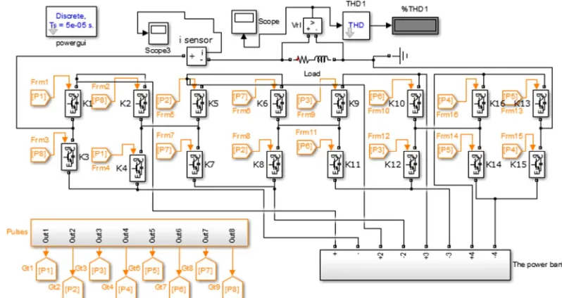
3.3 CHMLI in 17 levels mode
Figure 13 illustrates the 17 levels H-bridge topology used in Matlab Simulink. We carefully adopted the same SPWM command by adding the right number of carriers. The carrier repeats itself in time using the following law:
7
8 9 : 9
; 3 3<, 1 > ?2
3 3<, 2 > >2 1 7
Where: 7 is the carrier N°<, f is the carrier frequency, and ∈ B .
The reference signal can also in this case of 17 level CHMLI be expressed as:
C Dsin 2+H 8 Where: H is the reference signal frequency (50 JK in our this study)
[image:4.612.82.529.73.223.2]Figure 10: 9 levels H-bridge voltage output, unbalanced DC.
Figure 11: 9 levels H-bridge voltage spectrum, balanced DC.
[image:4.612.331.512.314.681.2]Figure 12: 9 levels H-bridge voltage spectrum, unbalanced DC.
[image:4.612.75.307.321.609.2]ISSN: 1992-8645 www.jatit.org E-ISSN: 1817-3195
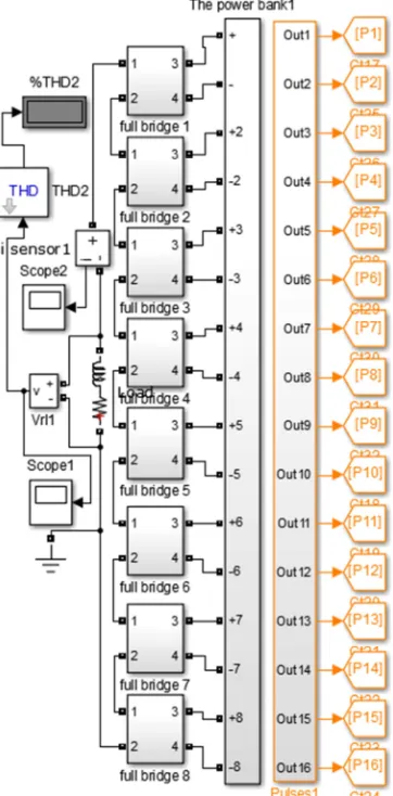
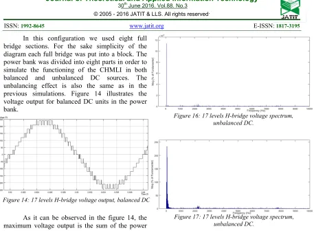
438 In this configuration we used eight full bridge sections. For the sake simplicity of the diagram each full bridge was put into a block. The power bank was divided into eight parts in order to simulate the functioning of the CHMLI in both balanced and unbalanced DC sources. The unbalancing effect is also the same as in the previous simulations. Figure 14 illustrates the voltage output for balanced DC units in the power bank.
As it can be observed in the figure 14, the maximum voltage output is the sum of the power bank units DC voltage 240V. In order to assess the impact of unbalanced batteries in the power bank on the 17 levels CHMLI, we generated the same unbalanced effect as before. Figure 15 represents the output voltage of the 17 levels cascaded H-bridge multilevel inverter with unbalanced storage units.
The Figure 15 shows that the output voltage peak is 205V as observed in previous configurations, which is the sum of the DC voltage values of the power bank storage units. Figure 16 and 17 show the 17 levels H-bridge output voltage spectrum analysis in both cases balanced and unbalanced power bank.
Spectral analysis of the 17 levels H-bridge multilevel inverter output voltage registered 7.85% when working with a balanced DC sources, and 9.2% when working in a 30% unbalanced power bank. We noticed that the DC units unbalancing has almost the same effect over the THD whether we work with a distributed or concentrated unbalancing effect, this is due to the fact that the DC storage unit’s share in the output sinusoidal signal is less and less important as we increase the level of the CHMLI.
4. SIMULATION RESULTS ANALYSIS
The study showed that the H-bridge multilevel inverter produces an output voltage with important THD when working in low levels. The THD however decreases as we increase the CHMLI level state. The DC storage units unbalancing is a major factor in increasing the THD value for a given multilevel inverter. However we can notice that the unbalancing impact is less important inside the power bank as we increase the multilevel inverter level; this is due to the fact that every unit’s contribution in the output signal is less important. The THD results are summarized in table 1 for the different cases studied.
[image:5.612.85.542.44.380.2]Figure 14: 17 levels H-bridge voltage output, balanced DC.
Figure 15: 17 levels H-bridge voltage output, unbalanced DC.
Figure 17: 17 levels H-bridge voltage spectrum, unbalanced DC.
[image:5.612.84.304.458.598.2]ISSN: 1992-8645 www.jatit.org E-ISSN: 1817-3195 439 CHMLI state Power bank sections
Dc voltage contribution per section (V) THD (balanced power bank) THD (unbalanced power bank)
5 2 120 35.12 % 43.9 %
9 4 60 22.75 % 28.6 %
17 8 30 7.85 % 9.2 %
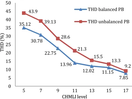
Table 1 confirms that the DC storage units in the power bank reduce their contribution to the output signal as the CHMLI level increases. Figure 18 illustrates how the THD level changes with the H-bridge multilevel inverter state.
In order to plot the chart in figure 18 we had to push our simulation tests to all the levels from 5 to 17. We can see that the same unbalancing effect in the power bank varies with level state increasing. We notice that the unbalancing impact is less important on power quality as the level is higher; the same unbalancing effect in 5 levels mode causes a difference of 8.8% between the two cases while in 17 levels mode it causes only 1.4% difference. Therefore if the level is high enough there is no need for technical measures to prevent unbalancing. This criterion is very needed in photovoltaic panels’ applications where the sun radiance in unpredictable over the day during very short periods of time, on cloudy days when the sun disappears suddenly for example.
5. CONCLUSION
In this article we studied the cascaded H-bridge multilevel inverter in many configurations and simulation conditions. We investigated this multilevel inverter in levels modes ranging from 5
to 17, namely we detailed the simulation of 5, 9 and 17. The study showed that the CHMLI works at its best performance in high levels. In our analysis we can say that the CHMLI compensates the Unbalancing problems caused by non distributed power charge on power bank units. In our study the 17 levels H-bridge inverter has proved to be a very reliable solution against unbalancing states in the power storage units. This study proved that a power conversion system based on a CHMLI is very reliable and cost efficient due to the fact that no special measures are needed to overcome the unbalancing problems. Therefore the CHMLI is capable of preserving the power storage units life time. Further work is planned to establish an efficient power management method in the power bank in order to keep balanced power availability at any time.
REFRENCES:
[1] BABAEI, Ebrahim, LAALI, Sara, et BAYAT, Zahra. A single-phase cascaded multilevel inverter based on a new basic unit with reduced number of power switches. Industrial Electronics, IEEE Transactions on, 2015, vol. 62, no 2, p. 922-929.
[2] MOKHBERDORAN, Ataollah et AJAMI, Alain. Symmetric and asymmetric design and implementation of new cascaded multilevel inverter topology. Power Electronics, IEEE Transactions on, 2014, vol. 29, no 12, p. 6712-6724.
[2] BANAEI, Mohammad Reza, JANNATI
OSKUEE, Mohammad Reza, et
KHOUNJAHAN, Hossein. Reconfiguration of semi-cascaded multilevel inverter to improve systems performance parameters. Power Electronics, IET, 2014, vol. 7, no 5, p. 1106-1112.
[4] XIAO, Bailu, HANG, Lijun, MEI, Jun, et al. Modular cascaded H-bridge multilevel PV inverter with distributed MPPT for grid-connected applications. Industry Applications, IEEE Transactions on, 2015, vol. 51, no 2, p. 1722-1731.
[5] PHARNE, I. D. et BHOSALE, Y. N. A review on multilevel inverter topology. In : Power, Energy and Control (ICPEC), 2013 International Conference on. IEEE, 2013. p. 700-703.
[6] GUPTA, Krishna Kumar, RANJAN, Alekh, BHATNAGAR, Pallavee, et al. Multilevel inverter topologies with reduced device count: a review. Power Electronics, IEEE Transactions on, 2016, vol. 31, no 1, p. 135-151.
Table 1: THD analysis summary
35.12
30.78
22.75 13.96
12.02 11.15 7.85 43.9
39.13
28.6
21.3
15.5 13.3
9.2 0 5 10 15 20 25 30 35 40 45 50
5 7 9 11 13 15 17
TH
D
%
CHMLI level
THD balanced PB
[image:6.612.82.298.293.456.2]THD unbalanced PB
ISSN: 1992-8645 www.jatit.org E-ISSN: 1817-3195
440 [7] BOLLER, Till, HOLTZ, Joachim, et
RATHORE, Akshay Kumar. Neutral-point potential balancing using synchronous optimal pulsewidth modulation of multilevel inverters in medium-voltage high-power AC drives. Industry Applications, IEEE Transactions on, 2014, vol. 50, no 1, p. 549-557.
[8] KIM, Mok, CHOI, Won-Shik, et PARK, Ki-Hyeon. Novel carrier-based hybrid pulse width modulation method for cascaded capacitor-clamp multilevel inverter. Power Electronics, IET, 2014, vol. 7, no 10, p. 2678-2686.
[9] PENG, Fang Z., QIAN, Wei, et CAO, Dong.
Recent advances in multilevel
converter/inverter topologies and applications. In : Power Electronics Conference (IPEC), 2010 International. IEEE, 2010. p. 492-501.
[10] LATRAN, Mohammad Barghi et TEKE, Ahmet. Investigation of multilevel multifunctional grid connected inverter topologies and control strategies used in photovoltaic systems. Renewable and Sustainable Energy Reviews, 2015, vol. 42, p. 361-376.
[11] KHALILI, Tajeddine, RAIHANI, Abdelhadi, OUAJJI, Hassan, et al. Efficient Choice of a Multilevel Inverter for Integration on a Hybrid Wind-Solar Power Station. Journal of Power and Energy Engineering, 2015, vol. 3, no 09, p. 44.
[12] COLAK, Ilhami, KABALCI, Ersan, et BAYINDIR, Ramazan. Review of multilevel voltage source inverter topologies and control schemes. Energy Conversion and Management, 2011, vol. 52, no 2, p. 1114-1128.
[13] DAHIDAH, Mohamed SA,KONSTANTINOU, Georgios, et AGELIDIS, Vassilios G. A review of multilevel selective harmonic elimination PWM: formulations, solving algorithms, implementation and applications. Power Electronics, IEEE Transactions on, 2015, vol. 30, no 8, p. 4091-4106.
[14] HAJIZADEH, Mehdi et FATHI, Seyed Hamid. Selective harmonic elimination strategy for cascaded H-bridge five-level inverter with arbitrary power sharing among the cells. IET Power Electronics, 2015.
[15] SEPAHVAND, Hossein, LIAO, Jingsheng, et FERDOWSI, Mehdi. Investigation on capacitor voltage regulation in cascaded H-bridge multilevel converters with fundamental frequency switching. Industrial Electronics, IEEE Transactions on, 2011, vol. 58, no 11, p. 5102-5111.