mDmDomD
---"
utility
program
DEC-15-YWZB-DN5
PDP - 1 5
PAT C H
UTI LIT Y
PROGRAM
PROGRAMMER'S REFERENCE MANUAL
For additional copies of this manual, order No. DEC-15-YWZB-DN5 from the
Program Library, Digital Equipment Corporation, Maynard, Massachusetts
First Printing, October 1971
Copyright
G)
by Digital Equipment Corporation
The information presented in this manual
is for informational purposes only and
may be changed without notice.
The following are trademarks of Digital Equipment
Corporation:
PDP
DIGITAL
PREFACE
This manual describes the operation and use of the PDP-IS PATCH Utility
Program. The PATCH program may be operated in either the ADVANCED
Software System (ADSSl or the Disk Operating System (DOS) environment.
NOTE
In DOS systems, PATCH may be used only by the System Manager.
It was assumed in the preparation of this manual that the reader was
familiar with the operation of the PDP-IS equipment and the contents
of the software manual describing the features of the particular
monitor system in which he was operating, that is:
a} for ADSS users, PDP-IS/20/30/40 ADVANCED Monitor Software System Manual, DEC-IS-MR2B-D;
bl for DOS user:~, DOS Software System User's Manual, DEC-IS-MRDA-D.
PDP-IS UTILITY PROGRF~S MANUAL, DEC-IS-YWZB-D
The PDP-IS Utility Programs manual is comprised of a set of individual
manuals, each of which describes the~eration and use of a PDP-IS
Utility Program. The manuals which make up the Utility Programs set
are listed in the following Application Guide. In addition, the
Appli-cation Guide also indicates the order number of each manual and the
specific PDP-IS Monitor Software Systems in which the program described
may be used.
The Utility Manuals may be ordered either individually, by using the
title and order number given with each manual or as a set by
referenc-ing "PDP-IS Utility Programs Manual, DEC-IS-YWZB-D".
APPLICATION GUIDE
PDP-iS UTILITY PROGRAM MANUALS
PDP-iS Utility Program Manuals and the Application of Each
Manual Applies to Monitor:
Title Order Number DOS ADV B/P
(DEC-1S-YWZB _)
DDT DNl
I
I
I
Utility Program
CHAIN & EXECUTE DN2
I
I
I
Utility Program
SGEN DN3
I
ADVANCED Monitor
MTDUMP DN4 I
I
I
Utility Program
PATCH DNS
I
I
I
Utility Program
I
I
I
EDIT DN6
I
I
I
Utility Program
UPDATE DN7
I
I
I
Utility Program
LINKING LOADER DN8
I
I
I
PIP DN9 I
I
ADVANCED Monitor
SRCCOM DNll
I
I
I
I Utilitv Pro ram -' g I I
I
I ISGEN DN12
I
DOS Monitor
PIP DN13 I
DOS Monitor
Disk SAVE/RESTORE DN14
I
II
Programs
CONTENTS
PREFACE
SECTION 1 1.1 1.2 1.3 1.4 1.5 INTRODUCTION PATCH PROGRAM
MANUAL ORGANIZATION AND USE SUPPORTING DOCUMENTS
MAJOR PATCH FUNCTIONS PATCH, I/O DATA FLOW PATHS
1-1 1-1
1-2 1-2
1-3
SECTION 2 SELECTION OF ITEM TO BE PATCHED 2.1 SELECT FUNCTION
2.1.1 Program Select Command 2.1.2 Block Select (B)
SECTION 3 LOADING RELOCATABLE PROGRAMS AS SYSTEM PROGRAMS
2-1 2-1 2-3
3.1 PATCH LOAD FUNCTION 3-1
3.2 PATCH READR LOAD COMMAND
3.2.1 Procedures
3.2.2 Input File Requirements
3.3 RELOCATION
3.3.1 PATCH READR File Relocation
3.4 BANK BIT INITIALIZATION (BBI) ROUTINE
3-1 3-2 3-2 3-3 3-3 3-4 3.5 READR ESTABLISHED SYSTEM COMMUNICATIONS AREA 3-5 3.6 LOADING PATCH-RELOCATED CORE IMAGE SYSTEM 3-6
PROGRAMS
SECTION 4 LOADING ABSOLUTE PROGRAMS AND DATA
4.1 READ AND PATCH FILE FUNCTIONS 4-1
4.2 READ LOAD FUNCTION 4-1
4.3 READ COMMAND 4-1
4.3.1 READ Load Operation 4-2
4.4 WRITING PATCH PROGRAMS 4-3
4.4.1 Partial Overlay Patch Programs 4-4 4.4.2 Replacing Complete Programs or Data Blocks 4-4 4.5 PRECAUTIONS TO BE OBSERVED FOR PATCH READ
OPERATIONS 4-4
SECTION 5 LISTING AND MODIFYING PROGRAM AND DATA BLOCK REGISTERS
5.1 REGISTER MODIFICATION FUNCTIONS 5-1
5.2 PATCH LIST FUNCTION
5.2.1 List Operation
5.2.2 Expressions
5.2.3 List Operation, Line Terminator
5.3 L LIST COMMAND
5.3.1 Example: Select, List and Modification Procedures
5.4 LR LIST COMMAND
5.4.1 LR, Register Modification Procedure
5.4.2 Relocation and LR List Operation Examples
5.5 SYSTEM PROGR&~ SYSBLK PARAMETER COMMANDS
5-1 5-2 5-2 5-4 5-4 5-5 5-6
5-7
5-8 5-10SECTION 6 SUMMARY, OPERATING PROCEDURES AND ERROR MESSAGES
6.1 CONTENTS
6.2 PRE-LOAD OPERATIONS
6.2.1 .DAT Slot Assignments
6.2.2 I/O Device Preparation
6.3 CALLING PATCH
6.4 PATCH OPERATIONS
6.4.1 Examination and Modification of Registers in Absolute Programs and Data Blocks
6.4.2 Examination and Modification of Registers in
6-1 6-1 6-1 6-1 6-2 6-2 6-2
PATCH-READR-insta11ed System Programs 6-2
6.4.3 Replacing Absolute Programs from External
PATCH Files 6-2
6.4.4 Installation of Re1ocatab1e Programs as
Absolute SYS Files 6-3
6.5 ERROR DETECTION 6-3
6.6 ERROR MESSAGES 6-3
APPENDIX A SYSTEM BLOCK (SYSBLK) DESCRIPTION A-1
APPENDIX B SYSTEM PROGRAMS, GENERAL DESCRIPTION B-1
INDEX X-1
TABLES
1-1
1-2
2-1
3 .... 1
5-1
5-2
6-3
6-4
FIGURES
1-1
A-I
A-2
B-1
Supporting Documentation
PATCH Operations, Information Flow Diagram
PATCH Accessible System Programs
Memory Map, Loading a READR-Installed SYS File on the ADSS Monitor
Operators Recognized by PATCH
List Operations, Command String Terminators
Required .DAT Slot Assigr~ents
Procedure for Modifying Registers in Absolute System Programs
Procedure for Modifying Registers in PATCH-Installed System Programs
Error Messages
PATCH Operations, Information Flow Diagram
System Block, Overall Configuration
System Program EDIT SYSBLK Parameter Group
Memory Map, Loading System Programs
vii
1-2
1-4
2-2
3-7
5-3
5-4
6-1
6-4
6-5
6-6
1-4
A-I
A-2
SECTION 1
INTRODUCTION
1.1 PATCH PROGRAM
The PATCH Utility program enables the PDP-IS user to view and modify
System Programs and data on specific device data blocks. The commands
provided by PATCH may be entered via the console keyboard or, in the
monitor Batch mode, via either paper tape or card reader units. This
manual is concerned only with user=controlled PATCH operations. The
operation of PATCH under monitor Batch control is described in the
applicable monitor (ADSS or DOS) reference manual (see Table l-l).
1.2 MANUAL ORGANIZATION AND USE
This manual is intended for users who are familiar with:
a) the general operating procedures (i.e., use of equip-ment and startup procedures) ,
b} the elements, structures and use of the particular monitor software system in which PATCH is to be used.
Introductory information and detailed descriptions of each PATCH
function and their awlications are given in Sections 2 through 5.
Section 6 summarizes the PATCH startup and operating procedures.
New users of PATCH should familiarize themselves with the contents
of Sections 1 through 5; thereafter, they need only refer to Section
6 for concise information.
Two Appendices are included which contain supplementary System Block
(SYSBLK) and System Program descriptions.
SYSBLK is described in Appendix A, System Programs are discussed in
Appendix B.
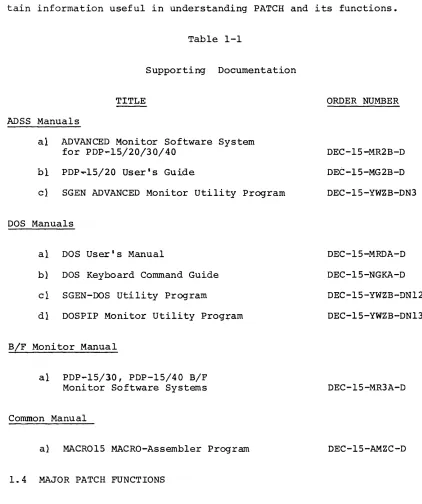
1.3 SUPPORTING DOCUMENTS
Table 1-1 lists PDP-1S documents which either support directly or
con-tain information useful in understanding PATCH and its functions.
Table 1-1
Supporting Documentation
TITLE ORDER NUMBER
ADSS Manuals
al ADVANCED Monitor Software System for PDP-lS/20/30/40
bi
PDP~lS/20 User1s Guidecl SGEN ADVANCED Monitor Utility Program
DOS Manuals
al DOS User1s Manual
b} DOS Keyboard Command Guide
cl SGEN-DOS utility Program
dl DOSPIP Monitor Utility Prog+am
B/F Monitor Manual
al PDP-1S/30, PDP-1S/40 B/F Monitor Software Systems
Common Manual
a} MACR01S MACRO-Assembler Program
1.4 MAJOR PATCH FUNCTIONS
DEC-1S-MR2B-D
DEC-1S-MG2B-D
DEC-1S-YWZB-DN3
DEC-1S-MRDA-D
DEC-1S-NGKA-D
DEC-1S-YWZB-DN12
DEC-1S-YWZB-DN13
DEC-1S-MR3A-D
DEC-1S-AMZC-D
The items on which PATCH functions may be performed together with a
description of the commands and procedures needed for their selection
are given in Section 2.
[image:11.612.76.498.109.613.2]The major functions for which PATCH may be used are:
a) the loading of relocatable programs into a system as a System Program (described in Section 3);
b} the loading of absolute programs and data onto a System Program area (described in Section 4);
c) the modification of registers located in
11 System Programs,
21 Data blocks,
31 System SYSBLK (system block).
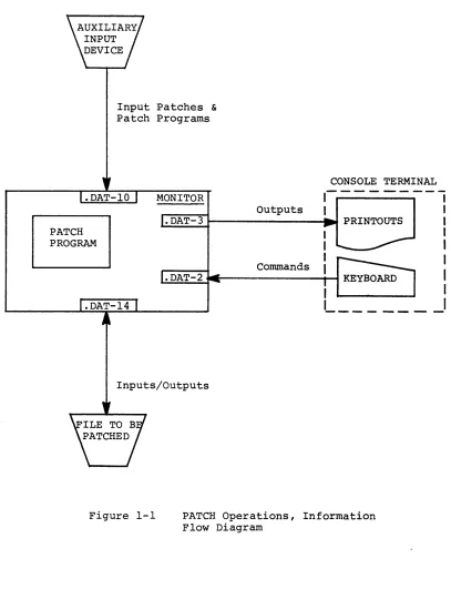
1.5 PATCH, I/O DATA FLOW PATHS
Figure 1-1 illustrates the primary data flow paths employed during
PATCH operations.
User command/response operations are carried out via a console/printer
unit, Peripheral deviceS/UFO's containing the files to be patched
must be assigned to .DAT-14, those devices containing auxiliary input
files must be assigned to .DAT-ID.
PATCH PROGRAM
Input Patches &
Patch Programs
MONITOR
Outputs
CONSOLE TERMINAL
,---"1
I
I~.~D~A~T~-~3~---~ PRINTOUTS I
I
Commands
Inputs/Outputs
1
I
1
I
1
1 _ _ _ - _ _ _ _
I
Figure 1-1 PATCH Operations, Information Flow Diagram
[image:13.612.87.494.86.626.2]SECTION 2
SELECTION OF ITEM TO BE PATCHED
2.1 SELECT FUNCTION
The first step required in any PATCH procedure is the selection of the i.te..TTI. (=DAT -14) to be patchel.. Two basic commands IlProgram Select" I
and "Block Selectll are provjded for this purpose.
2.1.1 Program Select COmITLand
The Syste..TTI. Programs located on the device assigned to .DAT -14 are selected for PATCH operations by the entry of a unique name which is stored in a monitor table; these unique names enable the monitor to identify the requested program.
The format for a Program Select command is:
>name)
For example, to select the Editor~ogram the entry
>EDIT)
is entered.
The entry of a System Program name merely identifies the item to be operated upon; no further action is taken until a PATCH function is initiated by another command.
NOTE
The Program Select command may be used only if the device assigned to .DAT -14 contains a Sys-tem Block (SYSBLK).
In addition to System Programs, system Device System Block (SYSBLK)
and CTRL Q (tQAREA) areas may also be selected for PATCH operations. Table 2-1 lists the unique names of the programs normally supplied as System Programs with ADSS and DOS software systems.
TABLE 2-1
PATCH Accessible System Programs
PROGRAM NAME
11 Resident Monitor RESMON
21 System Loader .SYSLD
31 Control Q Area tQAREA
41 Standard Editor Program EDIT
51 Text Editor for VT15 Graphics Display EDITVT
61
Text Editor for VP15 Storage TubeDisplay Unit EDITVP
71 Peripheral Interchange Program PIP 8) Macro-Imbedded Assembler for 8K
Systems Only MACRO I
9} MACR015, Macro-Assembler Program 10} Cross Reference Program
I I I CHAIN and EXECUTE Program
121 System Generator
131 System Generator, Section 2 14} System Generator, Section 3 IS} FORTRAN IV (16K)
MACRO CREF CHAIN SGEN .SGEN2 .SGEN3 F4 16} 171 18}
FORTRAN IV Imbedded (8K'Systems Only) F4I Core Dump Utility Program QFILE Dump Core Program
19} DECtape Copy Program 20} PATCH Program
211 UPDATE Program
221 Source Compare Program
23} Task Builder Program (RSX Only) 24} DOS Monitor
25} Keyboard Monitor, KM-15
26) 9-15 Keyboard Monitor, KM9-15
2-2 DUMP DTCOPY PATCH UPDATE SRCCOM TKB DOS15 Kr..f15 KM9-lS MONITOR DOS ADSS
2.1.2 Block Select (B)
A single 400
a
-word datatlock located on the device assigned to .DAT -14is selected for PATCH operations, using a IIBII Block Select command.
FORMATS:
where:
a) >B'-In)
or
bl >B+ '-In) (DECtape only)
or
cl >B-... n) (DECtape only)
11
B identifies the Block Select command21
+ indicates the selected block should be read in the forward direction.31
-
indicates that the selected block should be read in the reverse direction41
n represents an octal number which identifiesa logical block on the PATCH I/O device (.DAT -14). The value of n must be greater than or equal to
fJ.
DESCRIPTION:
The entry of a liB" select command relocates the identified word block
into a PATCH Block Buffer in core. In relocating the block, the load
address is set to ~, the size is set to 400
a,
and the block number isas specified. If the block number (n) in any of the select commands
is followed by a space, any data on the remainder of the input line is
treated as a comment and is ignored. For example:
>B
...
1;0~...
COMMENT)is permitted.
SECTION 3
LOADING RELOCATABLE PROGRAMS AS SYSTEM PROGRA~S
3.1 PATCH LOAD FUNCTION
A PATCH load function enables the user to convert a relocatable file
into an absolute SYS file format and load the converted file onto a
system device as a System Program. The PATCH command used, the
proce-dure required, the relocatable file requirements, and the operations
performed by PATCH are described in detail in this Section.
The PATCH load function can only be used when the system on .DAT
-14
has been prepared by SGEN to receive the converted file. During SGEN
procedures (refer to appropriate SGEN manual) the user must enter the
name of each program to be installed, specify .DAT slot usage, and
indicate the order in which the System Programs are to appear in the
newly generated system. The program name, size, and .DAT slot usage
information entered during SGEN is stored in the system device SYSBLK.
3 . 2 PATCH READ R LOAD COMHAND
The command "READRIJ initiates the PATCH relocatable-to-SYS file
pro-gram load function. The general format of this command is as follows:
>READR [nnnnnJ [filenameJ IextJ IcornmentsJ }
where:
nnnnn the highest l3-bit core address to be occupied by the relocated file when i t is loaded into core as a SYS file. If an address is not specified, the first free register below the bootstrap is assumed by PATCH. If specified, the value of nnnnn must
be ~176368; a larger value will cause an error.
filename the name of the relocatable file.1
ext filename extension; if not given, BIN is assumed.
comments if desired, a comment may be added to the command string, but only if the extension is given explicitly.
l NOTE : FILE na~e may be omitted for non-file oriented auxiliary
devices (.DAT -l~).
3.2.1 Procedures
Tne READR command must be preceded by a program select command which
identifies the system device area (named in SGEN) into which the
modi-fied file is to be written. For example, the sequence:
>STRN)
>READR STRAN)
must be entered to install the file STRAN onto a prepared system
de-vice at .DAT-14, given the name STRN.
On the execution of a READR command, PATCH obtains the named file from
.DAT-l~ and checks i t for required size and program characteristics
~ee paragraph 3.2.2}. If the file is not acceptable, the load
opera-tion is halted and an appropriate error message is output to the user.
If the file is acceptable, PATCH relocates addresses within the input
file, builds a table of the transfer vectors contained by the file,
and appends the table and a Bank Bit Initialization routine to the
file. The modified file and its appended routine and vector table are
then loaded as a unit, in core image form, onto the system device at
.DAT-14.
PATCH automatically changes the patch parameters in SYSBLK. Relocation
and the Bank Bit Initialization routines are described in paragraphs
3.3 and 3.4, respectively.
3.2.2 Input File Requirements
In order to be installed onto a system as a SYS file, a relocatable
file at .DAT-l~ must:
I} not contain more than 256 transfer vectors;
2} not contain external .GLOBL references;
31 not use indexed instructions
4) not have a core image size greater than the number of system blocks allocated multipliedwby 4~~8.
5) not cause the total program size to exceed SK.
6) not contain COMMON references
NOTE
The total installed size of a program may be computed by adding l} the size of the binary program, 2} the number of transfer vectors, and 3} 328 word locations which are occupied by the Bank Bit Inltialization routine.
3.3 RELOCATION
MACRO-1S outputs relocatable programs addressed as if they were
as-sembled starting in location ~ of core. Relocatable programs are
normally loaded into core for execution by the Linking Loader System
Program which, at load time, computes the difference between the
MACRO-assigned addresses and the addresses of the actual core area
into which the program is to be loaded for execution. This computed
difference, called the relocation factor, is then added to each
loca-tion address contained by the program qS i t is loaded into memory.
The relocation factor properly orients the relocatable program within
memory.
3.3.1 PATCH READR File Relocation
During the execution of a READR command, PATCH calculates the required
l3-bit relocation factor by subtracting the program size from the
final (highest) address the program is to occupy. The final address
is either specified in the READR command by the user or, by default,
17636
8 is assumed.
The relocation factor, recognized by PATCH as the symbol #, is then
incremented by 1 for each word location and the resulting value
as-signed as the address of the location. For example, the relocation
factor (#) for a relocatable program 4~~8 words in size with no address
specified in the READR command would be calculated:
#
=
176368 - 4~~8+
1=
172378In order to relocate the program addresses (~ through 377) for
con-version to the absolute values required for SYS files, PATCH then
increments the relocation factor by 1 for each position and assigns
each value obtained as an address to the corresponding program word
location; i.e.,
#
+ ~=
address of first word location (17237a)#
+
377 = address of last program word location (17636a)PATCH also relocates the addresses contained by the memory reference
instructions and transfer vectors found in the input program.
3.4 BANK BIT INITIALIZATION (BBI) ROUTINE
Transfer vectors contain l5-bit addresses which include bank identity
bits in addition to the l3-bit, aK word location addresses. The format
of a Transfer Vector data word and the interpretation of its address
portion is:
o
1 2 3I ; BANK
I
BANK BITS 1;
I
o
~1
0I
1 ~I 0
2~ll
3 ~ ,1
4
I
5 6I I
113-bit BANK WORD LOCATION ADDRESSES
1
I 1
o
I ... OOOOOa to 17777 a 1 1--" 20000a to 37777ao .-"
40000a to 57777 a 1 , .... 60000a to 77777 a
17
During READR relocation operations the relocation factor is added to
the least significant 13 word bits of the Transfer Vector to relocate
the bank word address which i t contains. The bank bits of a Transfer
Vector cannot be relocated at the time the file is installed as a System
Program since the number of the highest bank of a system varies
ac-cording to the overall size of the system.
To ensure that transfer vector bank bits are relocated prior to run
time, PATCH, during READR operations, develops a table of transfer
vector locations, adds the table to a Bank Bit Initialization routine,
and appends the routine to the input program. The BBI routine is
installed onto the system device medium as part of the new System
Program.
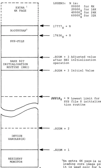
When a READR-installed program is loaded into core, its associated
BBI is also loaded immediately belowfue program (see Figure 3-1).
The loader, .SYSLD, on completion of its functions, turns control
over to the BBI routine. The BBI routine determines what bank the
System Program has been loaded into and updates the bank bits of all
Transfer Vectors contained by the program. The routine identifies
the vector words from the Transfer Vector table developed during
PATCH READR operations.
On completion of its initialization function, this routine sets the
contents of the .SCOM+3 pointer to fue address of the last word
loca-tion occupied by the routine and turns control over to the System
Program.
The modification of .SCOM+3 at the end of BBI functions frees the
core occupied by this routine for use by the System Program.
The basic portion of the BBI routine requires 328 word locations.
The routine Transfer Vector table requires an additional location for
each Vector in the program. A maximum of 4008 vectors is permitted.
The PATCH appended BBI routine relives the user of the responsibility
of including a routine to perform this function.
3.5 READR ESTABLISHED SYSTEM CO~~UNICATIONS AREA
The ability to specify in the READR command the highest load address
for the program being loaded permits a buffer area to be set up
between the last program address and the first address of the
boot-strap. Such a buffer would provide READR-Ioaded programs with a
common core-resident buffer for mtra-program communications and/or
common data storage.
BOOTSTRAP
BUFFER AREA
SYSTEM PROGRAM
BBI
~177778
~176368
~Specified Address
3.6 LOADING PATCH-RELOCATED CORE IMAGE SYSTEM PROGRA~S
READR-installed Systems Programs and their associated Device Handlers
are loaded into core from the system device by the System Loader
(.SYSLD) program.
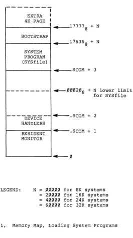
The placement of READR-installed System Programs and their device
handlers in core is illustrated in Figure 3-1.
r---~----,
I
I
I I
I
EXTRA 1
4K PAGE
BOOTSTRAP I
SYS-FILE
BANK BIT INITIALIZATION
ROUTINE (BBI)
~
C
-c
~
- - - -
I"~----DEVICE HANDLER(S)
RESIDENT MONITOR
LEGEND: N is:
00000 for 8K 20000
8 for 16K 40000
8 for 24K 60000
8 for 32K
177778 + N
17636
8 + N
. SCOM + 3 Adjusted value after BBI initialization operation
.SCOM + 3 Initial Value
~~~2~8
+
N Lowest Limit forSYS file $ initializa-tion routine
.SCOM + 2
.SCOM + 1
IAn extra 4K page is not used for loading core image programs, i t is used only for handlers.
Figure 3=1, Memory Map, Loading a P~ADR-Installed SYS-file on the ADSS Monitor
[image:24.617.178.521.81.653.2]SECTION 4
LOADING ABSOLUTE PROGRA~S &~D DATA
4.1 READ AND PATCH FILE FUNCTIONS
This section contains detailed descriptions of the READ load function,
the function user commands, and the load operation. Patch files, the
tnput sources to PATCH during READ load function, are also described
in detail.
4.2 READ LOAD FUNCTION
The IIREAD" load function enables the user to transfer absolute "Patch
filesll from the auxiliary input device (.DAT-lO) into a user-selected
program or data block located on the device at .DAT -14.
A Patch file is an absolute program written by the user to operate with
the PATCH READ load function; its purpose is to direct the PATCH program
in loading information contained by the file into a specific register
or series of registers located within a program or data block of the
device on .DAT-14. Entire programs or data blocks, as well as selected
items, may be loaded from Patch files onto the device at .DAT-14, using
the PATCH READ load function.
Patch files are used as a means of making changes (i.e. patches) to
SYS files or a device data block or of installing a new version of a
System Program onto a system device. They are particularly useful when
the same patches are to be made to a SYS file contained by more than
one system device.
NOTE
When patching or replacing a System Program, care must be taken to ensure either that the existing SYSBLK parameters are not affected or that they are changed to comply with the characteristics of the replacement version of the program (see
paragraph 4.5).
4. 3 READ COMMAND
The command READ initiates the performance of the absolute load
function. This command may have any of the following formats:
a) >READ) (for non-directoried devices only
b) >READ~[filenameJ)
c >READ~[filenameJ~[extJ)
where: I} filename is the name of the Patch file to be input from .DAT-IO. The use of a filename extension (format c) is optional. If not given, the extension is assumed to be ABS.
2) comments may be added to command strings having the format shown in item c.
3) Patch files on paper tapes do not require a filename (see item ~) .
NOTE
The READ command must be preceded by either a Program Select or Block Select command. The patch file read must be a .ABS macro program.
4.3.1 READ Load Operation
During READ command load operations, PATCH loads into core one 400 S -word block at a time from both the Patch File and the selected program
or data block. Once both blocks are loaded, PATCH processes in
sequence each word of the Patch File block. Using reference data
supplied in the Patch File, PATCH determines the address within the
user selected program or data block which corresponds to that
addressed by the Patch File word being processed. If the addressed
register is within the selected program or data block currently in
core, the contents of the Patch File word are loaded into that
register by PATCH.
If the addressed register is not in the block currently in core, the
block in core is written back into the device at .DAT-14 and the block
containing the addressed register is loaded. After the new block is
loaded, PATCH locates the addressed register and writes the contents
of the Patch File word into it.
A user-selected data block is handled, during READ operations, as if
i t were an absolute program having addresses ranging from ~~~~~
through ~~377S' If more than one data block is to be patched, a
separate Patch File is required for each block and individual Select
Block and READ commands must be issued for each.
If a Patch File word addresses a location not within the limits of
the selected program or block, PATCH outputs an ADDRESS OUT OF
RANGE error to the user console teleprinter (refer to Section 6
for description of error messages) .
4.4 WRITING PATCH PROGRAMS
The following is an example of the proper format for a PATCH assembly
source program to be assembled and output by MACRO-15:
PATCH FILE
. TITLE
.~S
. LOC 734777
6~~26l
.LOC -3
.LOC
~4~674
. END
anything NLD 234
35~
371
MEANING AND OPERATION PERFORMED
No Loader.
Set location counter to address 234 . Set contents of 234 to 734777, and go to next locat1on.
Set contents of 235 to 6~~261.
Advance counter to location 35~.
Set contents of 35~ to -3. Advance location counter to address 371.
Write ~4~674 into LOC 371
End program .
As illustrated in the above example, .LOC statements in the patch
program are recognized by PATCH as pointers. These pointers direct
PATCH to start a replacement operation at a specified address in the
program or data block being patched. In the replacement (overwrite)
operation, the contents of the Patch File location immediately
follow-ing the .LOC statement is written, by PATCH, into the selected program
or data block location pointed to by the .LOC address. PATCH then
writes, in sequence, the contents of the following Patch File locations
into the registers of the file being patched immediately following the
one pointed to by the patch file .LOC statement. All patches are
written as l i the program is to be loaded into the first bank (13
bit addresses). All transfer vectors in a .ABS program must be
The current replacement operation continues until another .LOC
state-ment is reached in the input Patch File. The new .LOC statement ends
the current replacement operation and directs PATCH to go to a new
start location and to start another replacement operation.
The Patch File operations are terminated when PATCH reaches the PATCH
File .END statement.
4.4.1 Partial Overlay Patch Programs
A Patch Program written to change the contents of specific locations
or groups of contiguous locations throughout a selected program or
data block acts as a partial patch to the file being modified; only
those items specified in the Patch Program are affected. The Patch
Program in example in paragraph 4.4 represents a partial patch.
Patch programs may only be used to change the contents of registers
already existing within a selected program or data block; they cannot
be used to insert information between existing program lines.
4.4.2 Replacing Complete Programs or Data Blocks
Patch Programs may be~itten to replace an entire absolute System
Program or 400
B-word data block. To accomplish this, the user sets
the first Patch File .LOC statement to point to the first location
of the program ordata block to be replaced and follows i t with the
replacement program or data block. For example:
.TITLE .ABS .LOC
t
Replacement Program or Block
I ~
.END
(Patch Program name) NLD
(First Location of selected program or data block)
4.5 PRECAUTIONS TO BE OBSERVED FOR PATCH READ OPERATIONS
The PATCH READ load operation does not modify (i.e., update) SYSBLK on
completion of the function. If any changes are made to a System Program
which affect the parameters stored for i t in SYSBLK, the user must
change these parameters using the PATCH List function (described in
Section 5). Indexed instructions are not permitted.
When overlaying a complete program with a new version, the user must
ensure that the new version will fit into the area allotted to that
program during SGEN. All .ABS program transfer vectors must be
bank-bit initialized by the program itself before i t uses them if the core
image is baded above 8K.
SECTION 5
LISTING AND MODIFYING PROGRAM AND DATA BLOCK REGISTERS
5.1 REGISTER MODIFICATION FUNCTIONS
This section describes the functions, commands and procedures which
eD_Mhle the user to select and modify individual registers within:
al
SYS files initially written as absolute programs,b1 READR-installed SYS files,
cl a system device SYSBLK Program Parameter Table, and
d1 a systa~ save, tQAREA, area.
5.2 PATCH LIST FUNCTION
PATCH register modification is carried out as a list operation in
which the address and contents of each register selected by the user
are listed (printed} on the user's console teleprinter. On completion
of the print operation, the user may enter, if desired, an expression
to replace the contents of the currently listed register. When the
user is through with the currently selected register, he terminates
that operation and either terminates. the function or directs PATCH
to list the contents and address of another register. The program
or data block containing the register(s} to be modified must be
identified by the entry of a Select command (see Section 2); the
specific register to be viewed and modified (if desired) is selected
by the user with a "List" command. Three types of List commands are
provided by PATCH:
al L command, used to select and initiate the list operation for registers within any selected SYS-file, data block, SYSBLK or QAREA contained by the device on .DAT -14.
b) LR command, used only for the selection and list-ing of registers within READR-installed SYSfiles.
cl SYSBLK Program Parameter Commands, five separate commands, each of which initiates the list opera-tion for a specific SYSBLK parameter for the cur-rently selected SYSfile. Used only with SYS files.
The format and use offue above List commands are described in
para-graphs 5-3, 5-4, and 5-5, respectively.
5.2.1 List Operation
The PATCH operations performed during a List operation are:
al On the entry of a list command, PATCH loads the 4008 word data block or selected Program block containing the user identified register into core. The selected register is opened by PATCH and its address and con-tents are printed on the console teleprinter unit.
bl PATCH waits for the entry of a modifier and/or a terminator.
cl PATCH writes the input modifier (if made) into the opened register and examines the line terminator to determine the next operation to be performed. De-pending on the terminator entered (see 5.2.3) PATCH
terminates the List function or opens another register.
5.2.2 Expressions
Expressions, as defined for MACRO-IS (see DEC-15-AMZA-D), are strings
of symbols and numbers separated by arithmetic or Boolean operators.
Octal numbers of from one to six digits (g to 777777
8) or alphanumeric symbols of from one to three characters may be used as expressions or
as components of an expression.
rn PATCH List operations, expressions are entered as replacements for
the contents of a program or data block register. Expressions entered
to change or modify a data word consist of up to six octal digits,
originally preceded by a minus sign; those entered for an instruction
word consist of an instruction operation code and an operand. PATCH
contains symbol tables for all of the PDP-IS basic instructions
op-codes and the operate group instructions with the octal values of
each. The user can, therefore, patch registers using symbolic rather
than octal representations of MACRO instructions (e.g., an expression
may
be entered as LAC 17536 instead of its octal form, 217536).The operators recognized by PATCH are listed in Table 5-1.
TABLE 5-1
Operators Recognized by PATCH
OPERATOR FUNCTION
+
-I
*I
(tabj
Two's complement subtraction
Inclusive OR
Two's complement addition
The asterisk (*
1
in addition to its use as an operator, also sets the expression by causing 2~~~~8 to be XORed into thevalue of the expression. The XOR operation occurs each time that the
symbol (*) is encountered; two sequential asterisks negate the setting
of the indirect bit. indirect bit of the
**
The value of a PATCH expression is null (no modification is made to
the opened register) unless the expression contains a number, symbol
or an asterisk.
Expressions are evaluated from left to right assuming an initial value
of zero followed by a + operator (i.e., 0 + User's expression).
Lead-ing and trailLead-ing operators are legal in an expression but the latter
are ignored. Whenever a string of consecutive operators is used, only
the last one in the string is used by PATCH in evaluating the expression.
NOTE
The LAW symbol is a special case in PATCH; i t should be used only in the following ways:
a) LAW
~ n which is equivalent to 76~~~~+n
bl LAW~-n which is equivalent to -no
The use of LAW in any manner other than that described below will result in an error.
[image:34.613.131.410.75.257.2]5.2.3 List Operation, Line Terminator
When all list operations for an opened register are completed, one of four possible Line Terminators is entered to close the register and indicate the next list operation. The line terminators are described in Table 5-2.
Table 5-2 List Operations, Command String Terminators
ENTRY DESCRIPTION OPERATION
)
Carriage Return Open and list the next sequential registert ) Up Arrow and Carriage Return
Open and List the register which precedes the current register. Treat any entries after t as a comment.
@
Back Arrow and Car-riage Return
ALT MODE
Open and list the contents of the register pointed to by the address portion of the word contained in the currently opened register. Treat any entries after + as a comment. Terminate current list operation; write PATCH buffer block onto
.DAT -14 and wait for next entry.
5.3 L List Command
The L List command has the following format:
where
L ...
n)
al L initiates the list operation, and
bi n represents the octal form of the l3-bit address of the location to be opened. When the L command is used to open registers of READR-installed SYS files the address n must be the relocated (i.e., address after relocation) value.
The response to an L command is a printout having the following format:
>address of opened location) / (contents of opened location)>
>L 132
>,0,0132/777435>
EXA."'1PLE
(location 132
8; contents 7774358)
After outputting the address and contents of the accessed location,
PATCH prints its go-ahead symbol (» and waits for:
1) the entry of an expression to replace the current con-tents, to modify the opened location.
For example:
> (address}/(current contents»(expression-new contents)
21 the entry of selected string terminator to indicate the next sequential list operation.
5.3.1 Example: Select, List and Modification Procedures
The following illustrates the use of PATCH select and list commands in
the modification of a hypothetical system program named JOVE.
PROCEDURE
>JOVE
>L 1,0,0 )
u0~1,0~/777435>
)~0,01~1/6,0,02,0,0>213775
)w,0,01,02/111215>,0,03,0~+-)
w0,0277/7,03112>it
>
DESCRIPTION
Select System Program JOVE.
Initiate List operation starting at loca-tion 1,0,0
PATCH prints address and contents of opened location; user enters ) to go to and open next sequential location.
Address and contents of location l~l are printed, user changes contents from
6,0~2,0,0 to 213775 and opens the next
sequen-tial location.
User modifies contents of location 1,02 and commands PATCH to go to and open the loca-tion addressed by the contents of localoca-tion 1~2 (i.e., location 3,0,0).
User enters
t )
to open and examine con-tents of preceding location (i.e., 277).User terminates current list operation by entering ALT MODE (symbol @).
PATCH prints a go-ahead symbol to indicate that i t is ready for the next operation.
5.4 LR LIST COMMAND
The LR List command has the following format:
where LR initiates the listing operation for a previously selected
READR-installed Systems Program, and!!. represents the 13 bit
"unrelo-cated" address (in octal) of "the program location to be opened.
NOTE
PATCH automatically calculates and adds the needed relocation factor to the user's entry (i.e., n). This enables the user to work directly from origi-nal unrelocated listings.
The major difference between the "L" and "LR" list operations is that
in L operations only absolute address information is output in responses
and is required in modification procedures. In LR operations, however,
the user must deal with both relocated and unrelocated addresses in
list printouts and in register modification procedures.
When the LR command is used to open word locations containing either
data or non-memory reference instructions, the responses output are
similar to those described for the L command. The only difference is
that in the LR responses the address of the accessed location is given
in relocated form relative to the original MACRO-assigned address.
NOTE
In the following paragraphs the symbol # is used to denote the relocation factor used by PATCH in the conversion of an unrelocated program into a system program.
To illustrate, assure~ that 6 is the unrelocated address of a
user-selected location containing a non-memory reference instruction or data
and that the relocation factor (#) is 17344. The response to the
command:
is printed in the following form:
>17344 + 6
/
nnnnnn >Relocated Address
Contents of location (6 digits) Op-Code and Operand or Data
For example:
>17352/017206>
To illustrate, assume that a relocation factor of 17642 is current and
that the selected program location l~l contains a JMP .+1 instruction.
The response to the command:
is printed in the following form:
Relocated Location Address (177642+101)
17743/617744<~~1~2>
Contents, Op-Code + # + Operand
(6~~~~~ + 17642 + 1~2
JMP=6fO~~~~
.+1 = l~l+l = 1~2
Unrelocated Operand, Referenced Address
(i.e., ~~1~2)
Printing an address operand in its unrelocated form enables the user to
easily recognize the instruction containing i t , and the referenced
lo-cation without calculating and subtracting the PATCH relolo-cation factor
( #) •
The unrelocated referenced address within a memory-reference type
instruc-tion is not printed by PATCH if i t is less than the first address of the
program; the address printed in angle brackets is always positive, though
i t may be zero.
5.4.1 LR, Register Modification Procedure
The contents of registers opened during LR operation are changed, as
for L list operations, by the entry of an expression which is to
re-place the contents of the current location.. New contents are entered
immediately after the listed response and replace the current contents
on termination of the response/user-input line.
Input expressions are formed using:
a. Octal numbers up to six digits in length; PATCH always assume a six-digit input and right-justifies all numeric inputs (e9g.,
an entry of 300S is recognized as 000300S). b. Operators (symbols) as listed in Table 5-1.
c. Symbolic representation of all PDP-IS basic instruction op-codes and operate group in-structions.
d. The symbol # to represent the relocation factor of the currently selected, READR-installed System Program.
Command string terminators indicate the next sequential operation to be carried out (refer to Table 5-2).
5.4.2 Relocation and LR List Operation Examples
The following examples use a single memory reference instruction to illustrate the relocation operations performed by READR in the instal-lation of a SYS file and the manner in which the instruction may sub-sequently be examined using the LR command.
EXAMPLE:
a. Assume the instruction LAC~300 located in MACRO as-signed location 200 of an unrelocated 400
S
-word pro-gram.b. The program is selected by the user and is ~ tched onto a prepared system device medium as a SYS file using the READR function/command.
Program Name
>Filename (name given at SGEN time)
>READR Filename (current name of program)
c. During READR operations, a relocation _-actor is cal-culated and added to all location addresses contained by the program. For a 400
S-word prograJl. #
=
l7237S•Therefore, the relocatable input memory reference instruction
LAC 300
is relocated as
(#+200 ) (LAC #+300)
which equals
174378 LAC 175378
or, in full octal form:
17437 217537
The relocated instruction is then output to the system device.
d. To examine the instruction given in step c. in a READR-installed SYS file, the user calls PATCH, selects the program, and uses the LR command
$PATCH >Filename >LRL-I200)
The responses output at the I/O console will be:
>17437/217537<~~3~~>
e. To change the contents of the location, the user enters the desired expression and terminates the command string. If the contents contain an address, the relocation factor must be added to fue new entry.
EXAMPLE:
For example, to change the address references in the con-tents of the location openedm step ~ from the 3008 to 3?5
8 (unrelocated values) ,the user must enter the
expres-s~on:
217544 8
if he knows the value of the relocation factor # (i.e.,
1 7 23 7 + 305).
or
LAC #+305 8
>17436/217537< ~~3~~> LACi+3,0'5 ~
changes the location to
17436/217544
/
and the terminator ) causes the next sequential loca-tion to be opened and a response output.
5.5 SYSTEM PROGRAM SYSBLK PARAMETER COMMANDS
PATCH provides, as a convenient for the user, five separate commands which obtain and modify, if desired, SYSBLK parameters for the user selected program currently in core. By entering the appropriate com-mand from the following list and using suitable terminators as listed
in Table 5-2, the user may start the listing at any specific point and proceed subsequently through the desired parameters.
The commands, the parameters opened, and the word positions are as follows:
Command SYSBLK Parameter Opened Word position
a} FB) Number of first block used 3
b) NB.J Number of blocks allotted to 4
program
c) FA,) First core address occupied 5
when the SYSfile is loaded into core (13-bits)
d) PS) Program Size 6
e) SA) Starting Address (13-bits) 7
When examining the parameter group of a READR-installed System Pro-gram, the user must remember that:
FA
PS
SA
will give the address of the first (lowest) core locations occupied by the System Pro-gram/BBI combination when i t is loaded.
will give the TOTAL size of the System Program/BBI combination.
will give the starting address of the BBI routine (first address above Transfer Vec-tor address table).
NOTE
The program system parameter commands may not be used:
a. when a program has not been selected or the command CTRL P (+F) has been entered;
b. when SYSBLK has been selected;
c. when the commands B, B+, or B- are in ef-fect.
The five SYSBLK Parameter commands operate in a manner similar to the
List (L) command. When entered, the corresponding parameter location
address and contents are printed out followed by a go-ahead symbol (»
as for the L command. As in other list operations, the user may,
ac-cording to the manner in which terminators are used: 1) modify the
opened register, 2) view the next sequential register, 3) view the
preceding register, 4) jump to and view the location addressed by the
contents of the last opened register, or 5) terminate the operation.
The operations initiated by a Parameter command are carried out on the
SYSBLK information contained by the PATCH command table. This SYSBLK
data is obtained by PATCH when i t is first loaded into core and prior
to the start of user PATCH operations . . On completion of each SYSBLK
Parameter command operation (ALT MODE terminator used), the modified
(or unchanged) command table SYSBLK is copied onto the system at .DAT-14.
Five separate commands are provided by PATCH as a convenience for the
user; they permit the user to obtain a specific parameter or to start
listing operations at a specific point with a simple straightforward
command. The complete series of five program parameters may be
ob-tained simply by starting with the FB command and advancing the
list-ing op~ration through the next four sequential word locations. This
method is the only way to modify .SYSBLK parameters without reloading
PATCH since i t also modifies the PATCH command table.
EXAMPLE:
The following example illustrates the use of a PATCH SYSBLK parameter
command to obtain and modify the first address occupied, program size
and starting address parameters for the system program currently in
core.
> FA.)
>
00066/013670> 13 660.J
00067/003747>3757 )
00070/01367l>1366l(ALT MODE)
5-11
parameter command
first address opened and modi-fied
SECTION 6
SUMMARY, OPERATING PROCEDURES AND ERROR MESSAGES
6.1 CONTENTS
Brief procedural descriptions of the operations needed before loading
the PATCH program and for the performance of each PATCH function are
given in this Section. Error detection and error messages are also
described.
6.2 PRE-LOAD OPERATIONS
6.2.1 .DAT Slot Assignments
The user must make the .DAT slot assignments given in Table 6-1
immediately prior to loading the PATCH program.
Table 6-1
.DAT Slot
-14
-10
Permanently { - 3 Assigned -2
Required .DAT Slot Assignments
Used to
Input from and output to the device on which patches are to be made.
The device handler is required only to perform .TRAN.
Input from the auxiliary device. The device handler must handle Dump Mode input and, if i t is for a non-file oriented device, must handle image alpha mode.
Output to the teleprinter.
Input from the console keyboard or batch processing device .
. DAT slot -10 can be assigned no device handler (NONE) if auxiliary
input is not required. .DAT slots -3 and -2 cannot be changed.
6.2.2 I/O Device Preparation
The user must ensure that the I/O device assigned to .DAT-14
(material to be patched) is WRITE ENABLED before starting PATCH
operations.
If the device is a
1.
2.
DECtape unit - set the unit's WRITE ENABLED/WRITE LOCK switch to the WRITE ENABLED position.
DECdisk - set the assigned logical disk unit's WRITE
LOCKOUT switches to their ENABLED positions. (RF Disk units only)
6.3 CALLING PATCH
PATCH is called by issuing the command PATCH from the system I/O
console. When PATCH is loaded and running, i t outputs its name
and version number. For example:
KM15 V5A $PATCH) PATCH Vnn
>
6.4 PATCH OPERATIONS
The operations which may be performed using PATCH fall into four (4)
functional groups. Procedures, in table form, are given for the List
ilL" and "LR" functions.
6.4.1 Examination and Modification of Registers in Absolute Programs and Data Blocks
See Table 6-2.
6.4.2 Examination and Modification of Registers in PATCH-READR-installed System Programs
See Table 6-3.
6.4.3 Replacing Absolute Programs from External PATCH Files
The required procedure is to:
a. Select Program or data block to be patched (e.g. >EDIT)).
b. Specify READ operation and input file with the command string
>READ~[filenameJ) (e.g., > READL...JEDPCH))
6.4.4 Installation of Relocatable as Absolute SYS
The required procedure is:
a. Select the system device area prepared (by SGEN) to receive the new SYS file (e. g. , >NUFIL) ) •
b. Enter the PATCH READR command using the following format:
> READRl.-Il1nnnn
J.£
i lenameJ)
(e.g., >READR~76~~~NUFIL)NOTE
nnnnn represents the highest register the new SYS file will occupy when loaded into core. In the example, this is specified as l76~~8 which would leave a 36
8-word buffer between the top of the SYS file and the first Bootstrap location.
6.5 ERROR DETECTION
PATCH, on the detection of an error, causes the following:
1) the current function is terminated;
2) the data block (program or selected block) current in the PATCH Block Buffer is output to the device at
.DAT-14 if modifications had been made to the block; 3) an appropriate error message is output at the user's
I/O terminal.
In the event of an .IOPS error, control is not automatically returned to the monitor. PATCH can be restarted by the entry of a CTRL P (iP)
command. CTRL P is also useful in terminating a read operation in the event of an equipment malfunction (e.g., paper tape reader jams).
In the event of an 111/0 device not readyll error (IOPS4), CTRL R may be used to continue the current operation after the device involved has
been made ready. CTRL C may also be used to return control to the monitor; however, care must be taken not to use this command when a register is open since any modification made to the current block in
core will be lost.
6.6 ERROR MESSAGES
The error messages output by PATCH are listed and described in
Table 6-4.
I
I
I
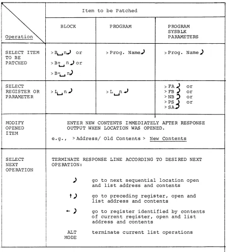
Item to be Patched
BLOCK PROGRAM PROGRAM
SYSBLK
Operation PARAMETERS
SELECT ITEM >I\...rV or > Prog. Name.) > Prog. Name) TO BE
PATCHED >B+n.)or
L..,I
> B-L..,I
n)
SELECT > FA) or
REGISTER OR >L~n) >L
n.J
> FB) orPARAMETER ~ >NB' or
>ps
3
or > SAMODIFY ENTER NEW CONTENTS IMMEDIATELY AFTER RESPONSE OPENED OUTPUT WHEN LOCATION WAS OPENED.
ITEM
SELECT NEXT OPERATION
e. g., > Address/ Old Con tents> New Contents
TERMINATE RESPONSE LINE ACCORDING TO DESIRED NEXT OPERATION:
)
t )
+- )
ALT
MODE
go to next sequential location open and list address and contents
go to preceding register, open and list address and contents
go to regist~r 'identified by contents of current register, open and list address and contents
terminate current list operations
Table 6-2, Procedure for Modifyinq Reqisters in Absolute System Proqrams
-
I
[image:47.612.81.527.66.561.2]SELECT ITEM
SELECT REGISTER
PARAMETER
MODIFY OPENED ITEM
SELECT NEXT OPERATION
OR
Item To Be Patched
PROGRAM
>
Prog. Name)>LR n )
'-'
PROGRAM SYSBLK PARAMETERS
>Prog. Name~
>PA) or >FB) or >NB"'.J or >PS) or >SA.J
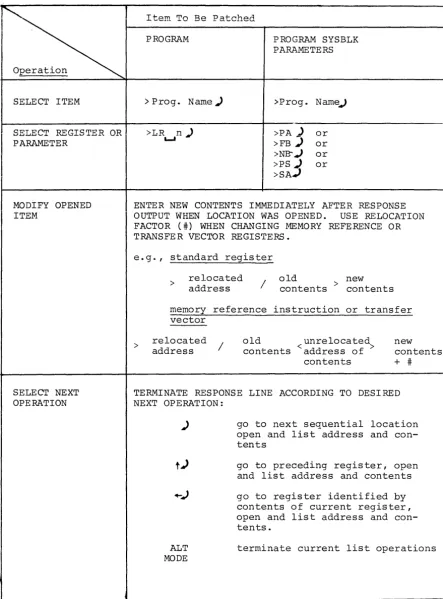
ENTER NEW CONTENTS IMMEDIATELY AFTER RESPONSE OUTPUT WHEN LOCATION WAS OPENED. USE RELOCATION FACTOR (#) WHEN CHANGING MEMORY REFERENCE OR TRANSFE R VECTOR REGISTERS.
e.g., standard register
>
> relocated
address
/
old > new contents contents
memory reference instruction or transfer vector
relocated address
/
old <unrelocated> contents address of
contents
new contents + #
TERMINATE RESPONSE LINE ACCORDING TO DESIRED NEXT OPERATION:
)
ALT
MODE
go to next sequential location open and list address and con-tents
go to preceding register, open and list address and contents
go to register identified by contents of current register, open and list address and con-tents.
terminate current list operations
Table 6-3. Procedure for Modifying Registers in PATCH-Installed System Programs
[image:48.618.94.538.76.676.2]Printout
ILLEGAL COMMAND
NOT OCTAL DIGIT
TOO MANY DIGITS
ADDRESS OUT OF RANGE
CHECKSUM ERROR
FILE NOT FOUND
ILLEGAL BLOCK #
ILLEGAL SIZE
MORE THAN 256 TRANSFER VECTORS
NOT RELOCATABLE BINARY
.GLOBL NOT ALLOWED
LAST ADDRESS GREATER THAN 17636
Table 6-4
ERROR MESSAGES
Meaning
a. An attempt was made to issue a command before a file or block was selected. b. Command unrecognizable.
A character other than an octal digit was encountered where an octal digit was expected.
The command string contains an octal number with more than 6 digits.
a. The address requested is not within the legal range of the currently selected program or block.
b. Address or size argument of a SYSBLK command is greater than 17645
8 or is negative.
Bad data read in from auxiliary input device (checksum, parity, or validity bits) - try again.
The file named in a READ or READR command does not exist on the auxiliary device.
The block number specified in a Block Selection command was less than ~.
a. The program size (PS command) exceeds the number of blocks allotted for the current program.
b. The size of the program (including the bank bit initialization routine supplied by PATCH) input by a READR command exceeds the number of blocks allotted (during system generation) for the SYS file or is greater than nnnnn-2~8.
The program being input by a READR command contains more than 256 transfer vectors.
The program being input by a READR command is not a relocatable binary file.
The program being input by a READR command contains an external .GLOBL (internal .GLOBL ignored) .
The last address of the program input by a READR command is greater than 17636
8.
APPENDIX A
SYSTEM BLOCK (SYSBLK) DESCRIPTION
A.l SYSTEM BLOCK (SYSBLK)
In each of the primary PDP-IS monitor systems (ADSS, DOS) the monitor
contains a System Block table (abbreviated as SYSBLK) which contains
the name, physical parameters and
VO
information for each system pro-gram in the software system.The information contained by SYSBLK in the initial operating system is
determined during System Generation procedures (refer to the
appropri-ate SGEN manual - Table 1-1). SYSBLK is used by the system loader
programs in locating and loading selected (called) System Programs into
core.
PATCH, when first loaded into core, checks for a SYSBLK at .DAT -14 and,
if one is present, i t loads the SYSBLK Parameter Table into core as a
PATCH Command Table. This command table is used unchanged during all
subsequent PATCH System Program operations, including SYSBLK
modifica-tion operamodifica-tions.
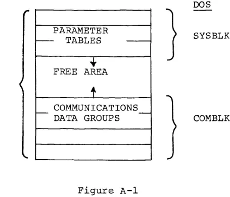
SYSBLK, itself, is divided into two distinct areas (see Figure 2-1), a
Parameter Table, and a Communications Table (named COMBLK in DOS systems).
PATCH operations normally concern only the SYSBLK Parameter Table.
ADSS DOS
PARAMETER
r--- TABLES
---•
}
SYSBLK
SYSBLK F~E AREA
t
COMMUNICATIONS
r - DATA GROUPS
---
COMBLKFigure A-I
System Block, Overall Configuration
[image:50.613.203.431.511.707.2]