CBASIC
Compiler™
Language
CBASIC® Compiler
Language
Graphics Guide
Copyr ight
©
1983Digital Research P.O. Box 579 801 Lighthouse Avenue Pacific Grove, CA 93950
TWX 910 360 5001
COPYRIGHT
Copyright ~ 1983 by Digital Research. All rights
reserved. No part of this publication may be
reproduced, transmitted, transcribed, stored in a retrieval system, or translated into any language or computer language, in any form or by any means, electronic, mechanical, magnetic, optical, chemical, manual or otherwise, without the prior written permission of Digital Research, Post Office Box 579, Pacific Grove, California, 93950.
DISCLAIMER
Dig i tal Research makes no represen ta tions or warranties with respect to the contents hereof and specifically disclaims any implied warranties of merchantabil i ty or fitness for any particular purpose. Further, Dig i tal Research reserves the right to revise this publication and to make changes from time to time in the content hereof without obligation of Digital Research to notify any person of such revision or changes.
TRADEMARKS
CP/M and CBASIC are registered trademarks of Digital Research. CBASIC Compiler, CB80, GSX, GSX-86, and LK80 are trademarks of Digital Research.
The CBASIC Compiler Language Graphics Guide was prepared using the Digital Research TEX Text Formatter and pr inted in the United States of America.
*********************************
*
First Edition: May 1983*
Foreword
CBASIC® Compiler is' Digital Research's powerful compiler
version of CBASIC, the commercial BASIC dialect recognized as the
industry standard.
With CBASIC Compiler's comprehensive, graphics
extensions, you can now write versatile graphics programs for a
multitude of applications.
Both the 8-bit and l6-bit versions of CBASIC Compiler support
graphics extensions.
To write graphics programs, you need CBASIC
Compiler and the GSX™ Graphics System Extension that fits your
CP/M® operating system and hardware.
CBASIC Compiler's graphics extensions are device-independent;
you can direct output to any graphics per ipheral wi thout recompiling
your programs. Your GSX software issues all the necessary commands
to control the peripherals you select.
For example, if you do not have a plotter, you needn't worry
about converting your programs for a plotter when one becomes
available.
You simply change the GSX ASSIGN.SYS file so that it
assigns your output to the plotter instead of to the screen. Your
GSX Graphics Extensions Programmer's Guide shows you how to modify
ASSIGN.SYS.
The GSX software contains routines that control the peripheral
devices. These routines, known as device drivers, provide physical
control of the devices. Your GSX guide includes specifications for
all the device drivers you can use with your software.
Get familiar with your software and hardware before you attempt
extensive application programming.
You can determine most of your
system's features by watching DEMOGRAF, the CBASIC Compiler graphics
tutorial.
This CBASIC Compiler Language Graphics Guide describes CBASIC
Compiler's graphics statements and functions with the assumption
that you are acquainted with CBASIC Compiler and GSX graphics.
• Section 1 defines the concepts underlying CBASIC Compiler
graphics.
• Section 2 explains how to compile and link CBASIC graphics
programs and discusses DEMOGRAF, a demonstration of CBASIC
Compiler's graphics statements and functions.
DEMOGRAF is
included on your demonstration disk.
Table of Contents
1 Introduction to CBASIC Compiler Graphics
1.1 Graphics Statements
1.2 Definitions
1. 2.1
1. 2.2
1. 2. 3
1. 2.4
1. 2.5
1. 2.6
1. 2. 7 1.2.8
Coordinates Bounds Viewport
Window • • • • Cursor
Beam Marker Clipping
2 Compiling and Linking
2.1 Compilation
2.2 Linking
2.3 GENGRAF
2.4 Run-time •
2 • 5 DEMOG RAF
3 Graphics Statements and Functions
BEAM Statement
BOUNDS Statement
CHARACTER HEIGHT Statement
CLEAR Statement •
CLIP Statement
COLOR Statement •
COLOR COUNT Statement .
DEVICE Statement
1-1 1-2 1-2 1-3 1-4 1-5 1-7 1-7 1-7 1-7 2-1 2-1 2-1 2-2 2-2 3-2 3-4 3-7
• • • 3-10
• • 3-11
• • 3-13
.0 . .
3-14. Table of Contents
( continued)
GRAPHIC OPEN Statement
GRAPHIC PRINT Statement •
JUSTIFY Statement • •
LINE STYLE Statement
MARKER HEIGHT Statement •
MARKER TYPE Statement • •
MAT FILL Statement
MAT MARKER Statement
MAT PLOT Statement
PLOT Statement
POSITION Statement
STYLE COUNT Statement • •
TEXT ANGLE Statement
VIEWPORT Statement
WINDOW Statement
4 Sample Functions and Programs
4.1 CIRCOM.BAS •
4.2 TSTCIR.BAS.
4.3 GRAPHR.BAS • •
Appendixes
A
DEMOGRAF Program Listing• 3-19
• • 3-20
• • • • 3-22
• • 3-25
• • 3-27
• • 3-30
• • • • 3-32
• • • 3-34
• • 3-36
• • 3-38
• • 3-40
• • 3-42
• • • 3-44
• 3-47
• • • 3-50
4-1
4-3
4-4
Tables, Figures, and Listings
Tables
1-1. Graphic Extensions by Functional Group
3-1. 3-2 3-3. Figures I-I. 1-2. 1-3. 3-1. 3-2. 3-3. 3-4. 3-5. 3-6. 3-7. 3-8. 3-9. 3-10. 3-11. 3-12. 3-13. 3-14. 3-15. 3-16. 3-17. 3-18. 3-19. 3-20. Listings 4-1. 4-2. 4-3. A-I.
Syntax Definitions • • • • • Marker Types • • • • • Degrees-to-Radians Conversion Chart
Device Coordinates Viewport • • • • • Window • • • • • •
The BEAM Statement • • •
The BOUNDS Statement--Rectangle The BOUNDS Statement--Square
The CHARACTER HEIGHT Statement • • • • Unclipped Image • • • • • • •
Clipped Image • • • • • • • • The GRAPHIC INPUT Statement • The JUSTIFY Statement • • • • The LINE STYLE Statement • • • • • The MARKER HEIGHT Statement • The MARKER TYPE Statement •
The MAT FILL Statement • • • • • • The MAT MARKER Statement
The MAT PLOT Statement • • • • • The PLOT Statement • • • • • • • • The POSITION Statement • • • • • The STYLE COUNT Statement
The TEXT ANGLE Statement • • • • • The VIEWPORT Statement • • • • • • The WINDOW Statement
CIRCOM.BAS Program TSTCIR.BAS Program GRAPHR.BAS Program
DEMOGRAF Program •
1-1
3-1 • 3-30 • • • 3-44
1-3 1-4 1-6 3-3 3-6 3-6 3-9 3-12 • • • 3-12 3-18 • 3-24 • • 3-26 3-29 3-31 • • 3-33 • • 3-35 • 3-37 • 3-39 • 3-41 • 3-43 • • 3-46 • 3-49 • • • 3-51
4-1 4-3 4-4
Section 1
Introduction to CBASIC Compiler Graphics
This section introduces the CBASIC Compiler graphics statements and functions and defines some elementary graphics concepts.
1.1 Graphics Statements
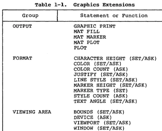
The graphics statements and functions fall into five groups, according to function. Each statement or function is described individually in Section 3. The names of CBASIC Compiler graphics statements and functions are reserved words.
Table 1-1. Graphics Extensions
Group
OUTPUT
FORMAT
VIEWING AREA
Statement or Function
GRAPHIC PRINT MAT FILL MAT MARKER MAT PLOT PLOT
CHARACTER HEIGHT (SET/ASK) COLOR (SET/ASI<)
COLOR COUNT (ASK) JUSTIFY (SET/ASK) LINE STYLE (SET/ASK) MARKER HEIGHT (SET/ASK) MARKER TYPE (SET) STYLE COUNT (ASK) TEXT ANGLE (SET/ASK)
[image:10.475.108.380.208.427.2]CBASIC Compiler Graphics Guide
1.1 Graphics Statements
Table 1-1.
(continued)
Group
INPUT
CONTROL
1.2 Definitions
I
Statement or Function
GRAPHIC INPUT
BEAM (SET/ASK)
CLEAR
CLIP (SET/ASK)
GRAPHIC CLOSE
GRAPHIC OPEN
POSITION (SET/ASK)
You should understand the following concepts before you turn
to the statement and function definitions.
1.2.1 Coordinates
Positions within the display area of the graphics device are
defined by X and Y coordinates. The X axis is the horizontal axis.
The Y axis is the vertical axis. Both coordinate axes begin at the
lower left corner of the device.
When you initialize the graphics system with the GRAPHIC OPEN
statement, the coordinates initially range from 0.0 to 1.0 for both
axes, regardless of the physical dimensions of the device.
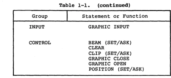
After you initialize a device with the GRAPHIC OPEN
statement, your program can address the lower left corner of the
display device with X and Y coordinates 0,0. The upper right corner
of the device is address 1,1. You define a box around the border of
your graphics output device by connecting the coordinate pairs
[image:11.476.73.368.58.192.2]CBASIC Compiler Graphics Guide 1.2 Definitions
0,1 1,1
y
0,0
x
1,0Figure 1-1. Device Coordinates
1.2.2 Bounds
The bounds of a device are its physical dimensions in pixels, inches, or whatever measure a particular device uses. Frequently, these dimensions are not the same for the X and Y axes. The height of the drawing area might not be equal to the width. with the BOUNDS statement, you can control the the length of the axes, thus keeping your images proportioned, regardless of the device you are using.
After a GRAPHIC OPEN statement, the bounds of the device are set to 100% of the physical extent of the X and Y axes. If there is a difference in the extents of the two axes, a line along the X axis is not the same length as a line along the Y axis. For example, the Y axis might be shorter relative to the X axis. The ratio of the Y axis to the X axis is called the aspect ratio.
You can use the DEVICE statement to determine the aspect ratio of a device. For example, if the Y axis is 80% as long as the X axis, the ASK DEVICE statement returns 1.0 and .8 as the relative values of the X and Y axes.
[image:12.474.109.370.60.247.2]CBASIC Compiler Graphics Guide 1.2 Definitions
1.2.3 Viewport
within the bounds of a device, the area in which graphics data prints is called the viewport. You define the viewport by X and Y coordinates ranging from 0.0 to 1.0.
Use the VIEWPORT statement to define the literal viewing area within the physical bounds of the device. VIEWPORT lets you specify beginning and end points for the X and Y axes within the device's current bounds. Subsequent graphics statements operate inside the area you specify in the VIEWPORT statement.
Figure 1-2 illustrates a viewport. You establish this viewport with the following statement:
SET VIEWPORT .2,.5,.2,.6
0,1 1,1
.2,.6 .5,.6
y
I
VIEWPORT
I
.2,.2 .5,.2
0,0
x
0,1Figure 1-2. Viewport
All graphics statements after the VIEWPORT statement refer to the area within this viewport.
In this case the bounds of the device are 100% of the available capacity. If you use a SET BOUNDS statement to alter the extents of thedev ice, the viewport automatically adjusts within the new
[image:13.473.85.379.163.400.2]CBASIC Compiler Graphics Guide 1. 2 Definitions
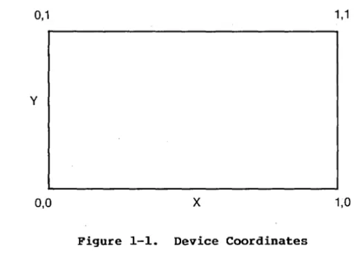
1.2.4 Window
You can think of a window as a frame with tick marks around the vi ewpor t • The window de fines the scale of the X and Y coordinates of a viewport. With the WINDOW statement, you can restate the scale of the viewport coordinate system to whatever values your application requires.
The WINDOW statement lets you automatically map real-world values onto the coordinate system of your device. The X and Y coordinates of a viewport initially range from 0.0 to 1.0. You can change the initial viewport ranges with the WINDOW statement. WINDOW can adjust these ranges to the scale required by your application. For example,
SET WINDOW 0,100,0,100
scales all coordinate references in subsequent CBASIC graphics statements to a range of 0 to 100 for both axes.
In summary, the window scales the viewport; the viewport resides within the bounds; the bounds reside within the physical
extents of the device. For further information, see the
CBASIC Compiler Graphics Guide 1.2 Definitions
y
o
\ \
\
DEVICE
\ \
\ \
\
THE BOUNDS ARE MAPPED WITHIN THE DEVICE
"
"
THE VIEWPORT IS MAPPED WITHIN THE BOUNDS
"
"
"
"
"
"
" 'VIEWPORT"
o x "
1 " , THE VIEWPORT" "
[ii]
'"
THE WINDOW SCALES"
"
" "
"
"
,
"
'smINDDW 0,100,0 .too '
,,<:°1
'D'1
PLOT (45,0) '(55,0) '(55,80) '(80,80) " PLOT (50,70) '(40,80) 1145,80) 1145,0) 0
o X 100
[image:15.475.49.405.62.496.2]CBASIC Compiler Graphics Guide
1.2 Definitions
1.2.5
Graphics Cursor
The cursor indicates the current location of the drawing
device. The GRAPHIC INPUT statement has a special graphics cursor
tha t you can maneuver around the screen.
How you control the
movement of the graphics cursor (arrow keys, control keys, or a
mouse), depends on your hardware. See your GSX Graphics Extension
Programmer's Guide.
1.2.6
Beam
The beam is the drawing device within a particular output
device. For a plotter, the beam is a pen. For a CRT, the beam is a
stream of electrons.
You turn the beam on or off with the BEAM
statement.
1.2.7
Marker
Markers are predefined symbols you use to identify points or
intersections on a graph or drawing.
You can use the MAT MARKER
statement to plot a scatter graph of points with markers.
The
available markers are descr ibed in the documentation for your device
driver.
See the MARKER TYPE statement in Section 3.
1.2.8
Clipping
Sometimes the coordinate references you give are
out-of-bounds, extending beyond the bit-map memory area that some devices
use to generate displays. Clipping refers to the chopping off of
parts of drawings that would otherwise trespass beyond this area.
Without clipping, memory outside the bit-map area might be altered.
Use the CLIP statement to turn clipping on or off. Clipping
is on by default at the beginning of a program.
Turning clipping
off increases operating speed slightly, but is risky. Turn clipping
off only if you are sure that your application program will not try
to reference coordinates outside the current window.
See the CLIP
statement in Section 3.
Section 2
Compiling and Linking
To create object programs from CBASIC Compiler graphics programs, you need special files and procedures. This section explains these requirements and tells you how to compile, link, and run DEMOGRAF, the graphics demonstration program.
2.1 Compilation
Your source program must include the following statement:
%INCLUDE GRAPHCOM.BAS
The statement above assumes the file GRAPHCOM.BAS is on the same disk drive as the source program. If i t is on a different drive, precede the filename in the %INCLUDE statement with a drive specification. For example,
%INCLUDE B:GRAPHCOM.BAS
The GRAPHCOM.BAS file contains var iable names to include in the common program area. The variable names in this file are reserved words in CBASIC Compiler programs that use graphics statements.
2.2 Linking
You need no special procedures to link CBASIC Compiler graphics programs. Follow the instructions in your CBASIC Compiler documentation.
2.3 GENGRAF
Use the GENGRAF program to incorporate run-time loaders into programs generated by the 8-bit CBASIC Compiler, CB80™. If you are a l6-bi t CBASIC Compiler (CB86 TM) user, you do not need GENGRAF, nor do you need to follow this procedure. The form of the GENGRAF command is
GENGRAF <filespec>
CBASIC Compiler Graphics Guide
2.4 Run-time
2.4 Run-time
At run-time, the following files must be on the current default
drive:
CBASIC Compiler (CB80) Users
• GSX.SYS
• ASSIGN.SYS
• Device drivers as required by ASSIGN.SYS
CBASIC Compiler (CB86) Users
• GRAPHICS.CMD
• ASSIGN.SYS
• Device drivers as required by ASSIGN.SYS
See your GSX Graphics Extension Programmer's Guide for details
regarding these files.
2.5
DEMOGRAF
A graphics tutorial, DEMOGRAF.BAS, is included on your CBASIC
software disk. It contains examples of all the graphics statements.
The examples are the same as those shown in the definitions of the
graphics statements and functions in Section 3. The tutorial is in
al phabe tical order like Sect ion 3.
A program list ing of
DEMOGRAF.BAS is included in Appendix A.
To use the demonstration program, you must first compile and
link the source program DEMOGRAF.BAS, using one of the following
procedures:
o CBASIC Compiler (CB80) Users
A>CB80 DEMOGRAF
A>LK80 DEMOGRAF
CBASIC Compiler Graphics Guide 2.5 DEMOGRAF
o CBASIC Compiler (CB86) Users
A>CB86 DEMOGRAF
A>LINK86 DEMOGRAF
A> GRAPHICS (load GSX-86™ )
To run the DEMOGRAF program, enter the following command:
A>DEMOGRAF
DEMOGRAF contains statement demonstrations that display the name of the statement and show how i t works. Read the explanations of the graphics statements in Section 3 as you watch DEMOGRAF.
DEMOGRAF pauses at the end of each example. Press any key to continue. Enter CTRL-C to interrupt and return to the operating system.
Section 3
Graphics Statements and Functions
This section presents the CBASIC Compiler graphics statements and functions in alphabetical order. Statement keywords preceded by SET and ASK are alphabetized by the keyword. For example, the SET WINDOW statement is found under WINDOW.
The syntax notation in this guide employs the following conventions.
• Upper-case letters designate CBASIC Compiler keywords.
• Lower-case letters indicate variables.
• Angle brackets < > enclose syntactic items.
• Square brackets [ ] enclose optional items.
• Braces { } enclose optional items that can be repeated.
• The OR bar,
I,
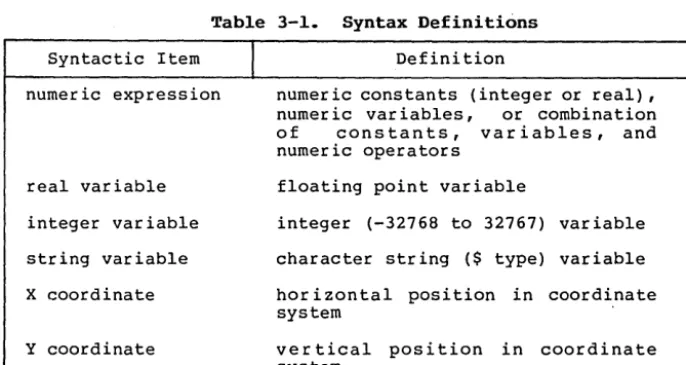
indicates a choice between two or more syntactic items.You must include all other punctuation in the syntax line, such as delimi ters and parentheses. Table 3-1 defines some syntactic items:
Table 3-1. Syntax Definitions
Syntactic Item
numeric expression
real variable
integer variable
string variable
X coordinate
Y coordinate
I
Definitionnumeric constants (integer or real), numer ic var iables, or combination of constants, variables, and numeric operators
floating point variable
integer (-32768 to 32767) variable
character string ($ type) variable
hor i zon tal position in coordinate system
[image:22.480.72.415.347.529.2]CBASIC Compiler Graphics Guide
BEAM Statement
BEAM Statement
The BEAM statement turns the pen or drawing beam on or off.
Syntax:
SET BEAM "ON"
I
"OFF"
ASK BEAM <string variable>
Explanation:
Switch the beam on or off by writing a SET BEAM statement with
"ON" or "OFF", upper-case and in quotation marks, as the argument.
This statement is like a PEN UP/PEN DOWN statement for a plotter.
The ASK BEAM statement tells you whether the beam is currently
on or off, returning the value of the beam state in <string
variable>.
Example:
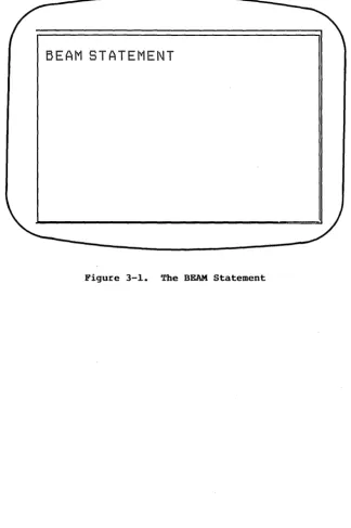
GRAPHIC PRINT AT (0,.9): "BEAM STATEMENT"
SET BEAM "OFF"
PLOT
(0, 1) , (1, 1) , (1, 0) , (0 , 0 )KEY%=PAUSE
REM
PAUSE IS A LOCALLY DEFINED FUNCTION
REM
THAT WAITS FOR CONSOLE INPUT.
CLEAR
SET BEAM "ON"
PLOT
(0,1), (1,1) , (1,0) , (0,0)KEY%=PAUSE
In this example, the SET BEAM "OFF" statement turns off the
beam before the PLOT statement runs. Only three sides of a screen
border are drawn, because the beam is OFF before the first pair of
coordinates is plotted (see Figure 3-1).
PAUSE is locally defined at the beginning of DEMOGRAF.
The
pause halts the program so you can see the display.
Press any key
to continue.
To interrupt the program, enter CTRL-C.
The CLEAR statement turns the beam off and leaves it at
0,0.CBASIC Compiler Graphics Guide
BEAM Statement
BEAM STATEMENT
[image:24.476.79.404.75.563.2]CBASIC Compiler Graphics Guide
BOUNDS Statement
BOUNDS Statement
The BOUNDS statement sets the aspect ratio of the X and Y axes
of the output device.
Syntax:
SET BOUNDS <height>,<width>
ASK BOUNDS <height>,<width>
Explanation:
Graphics devices often have different horizontal and vertical
dimensions.
The ratio of the length of the axes is called the
aspect ratio.
The BOUNDS statement changes the aspect ratio.
(To find the
aspect ratio of the device, use the ASK DEVICE statement.) The
values you give for the new height and width of the device must be
greater than 0.0 and less than or equal to.l.O. At least one of the
values must be equal to 1.0.
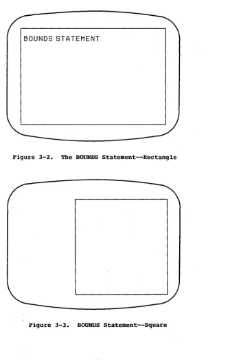
The new boundar ies of the device are always anchored at
coordinates 0,0, as shown in Figures 3-2 and 3-3.
All subsequent
graphics operations are bounded by the new height and width of the
SET BOUNDS statement.
ASK BOUNDS ass igns the cur rent ver tical and hor izontal
dimensions of the screen to the real variables <height> and <width>.
CBASIC Compiler Graphics Guide BOUNDS Statement
Example:
You can use the BOUNDS statement with the ASK DEVICE statement to alter the aspect ratio of a device.
CLEAR
GRAPHIC PRINT AT (O,.9): "BOUNDS STATEMENT" ASK DEVICE X.AXIS,Y.AXIS
PRINT "THE ASPECT RATIO IS= "; Y.AXIS; "/"; X.AXIS KEY% = PAUSE
REM PAUSE IS A LOCALLY DEFINED FUNCTION PLOT (O, 0) , (O ,1) , (I, 1) , (I, 0) , (O, 0) KEY% = PAUSE
CLEAR
SET BOUNDS Y.AXIS,X.AXIS
PLOT (O, 0) , (O , 1) , (I, 1) , (I, 0) , (O , 0 ) SET BOUNDS 1,1
The second PLOT statement draws a perfect square because reversing the physical dimensions in the SET BOUNDS statement squares the aspect ratio of the screen.
CBASIC Compiler Graphics Guide BOUNDS Statement
BOUNDS STATEMENT
Figure 3-2. The BOUNDS Statement--Rectangle
[image:27.478.90.425.51.574.2]CBASIC Compiler Graphics Guide
CHARACTER HEIGHT Statement
CHARACTER HEIGHT Statement
The CHARACTER HEIGHT statement defines the height of characters
or assigns the height to a variable.
Syntax:
SET CHARACTER HEIGHT <numeric expression>
ASK CHARACTER HEIGHT <real variable>
Explanation:
SET CHARACTER HEIGHT defines the height of characters relative
to the length of the Y coordinate. Initially, Y extends from 0.0 to
1.0. A character height of .2 results in characters that are 20% of
the length of the Y coordinate.
The argument you give for <numeric expression> is the desired
height of the character.
The resulting character height is the
largest hardware character size that does not exceed the size you
requested.
Every output device has a number of character sizes.
You can find the character sets of the output devices available to
your system in your GSX reference manual.
SET CHARACTER HEIGHT 0 sets the character height to the minimum
size possible within the current window.
ASK CHARACTER HEIGHT assigns the current character height value
to the <real variable>.
You can use ASK CHARACTER HEIGHT to find
the height assigned by a previous SET CHARACTER HEIGHT statement.
The actual value of a character height can differ from what you
specify in a SET CHARACTER HEIGHT statement, because the choice of
character heights is determined by the available character set.
You can change the extent of the X and. Y coordinates with the
WINDOW statement.
After such a change, any CHARACTER HEIGHT
statements use the new X and Y coordinate extents as a base. If you
use WINDOW to change the Y coordinate to 0.0 to 100.0, the correct
value for a 20% character height is 20.0.
CBASIC Compiler Graphics Guide CHARACTER HEIGHT Statement
For example, the minimum character height in a large window is greater than the minimum character height in a small window. If you start with a large window and shrink the window without changing the size of the characters, the characters might not fit in a smaller window. If not, they do not print.
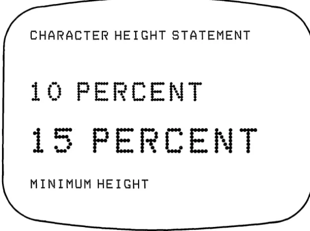
~xamples:
The following statement sets the character height to 10% of the screen if the extent of the Y coordinate is 0.0 to 1.0.
SET CHARACTER HEIGHT .1
The following statement sets the character height to 15% (15/100) of the screen. The window statement has set the Y axis to a value ranging from
°
to 100.SET WINDOW 0,100,0,100 SET CHARACTER HEIGHT 15
The next routine returns the minimum character height in the numeric variable CH:
SET CHARACTER HEIGHT
°
ASK CHARACTER HEIGHT CHPRINT "MINIMUM DEVICE CHARACTER HEIGHT IS = ": CH
The CHARACTER HEIGHT demonstration in the DEMOGRAF program is performed by the following commands:
CLEAR
SET CHARACTER HEIGHT
°
GRAPHIC PRINT AT (0,.9): "CHARACTER HEIGHT STATEMENT" SET CHARACTER HEIGHT .1
GRAPHIC PRINT AT (0,.7): "10 PERCENT" KEY%
=
PAUSEREM PAUSE IS A LOCALLY DEFINED FUNCTION SET WINDOW 0,100,0,100
SET CHARACTER HEIGHT 15
GRAPHIC PRINT AT (0,40): "15 PERCENT" KEY% = PAUSE
SET CHARACTER HEIGHT
°
ASK CHARACTER HEIGHT CHCBASIC Compiler Graphics Guide CHARACTER HEIGHT Statement
CHARACTER HE I GHT STATEMENT
1 (:)
PEJ;'CEt\JT
15
PERCEt~T
MINIMUM HEIGHT
[image:30.475.82.394.72.304.2]CBASIC Compiler Graphics Guide CLEAR Statement
CLEAR Statement
Syntax:
CLEAR
Explanation:
The CLEAR statement clears the screen, returns the cursor to (0,0), and turns the beam off.
Example:
INPUT un: LINE SEED$ RANDOMIZE
CLEAR
GRAPHIC PRINT AT (0,90): "CLEAR STATEMENT" SET WINDOW 0,1,0,1
FOR I.INT% = 1 TO 10
PLOT (RND,RND), (RND,RND) NEXT I.INT%
KEY%
=
PAUSEREM PAUSE IS A LOCALLY DEFINED FUNCTION CLEAR
CBASIC Compiler Graphics Guide
CLIP Statement
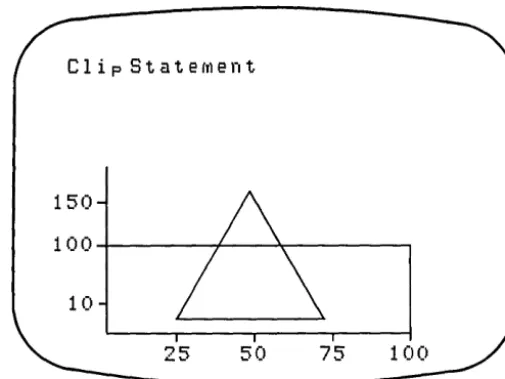
'CLIP Statement
The CLIP statement turns clipping on or off.
Syntax:
SET CLIP "ON"
I
"OFF"
ASK CLIP <string variable>
Explanation:
SET CLIP requires a str ing expression "ON" or "OFF", upper-case
and in quotation marks, as the argument.
ASK CLIP returns the
current value of the clip state in <string variable>.
Clipping edits portions of line segments or figures that extend
outside the limits of the current window. With clipping on, memory
areas in a bit-mapped display device are protected from possible
overlay by out-of-range coordinate references.
It is advisable to keep clipping on.
Otherwise, you might
overlay data that the software or hardware needs to operate.
Example:
This program illustrates the effect of automatic clipping when
a figure exceeds allowable boundar ies.
Figure 3-5 shows the
unclipped image. With clipping OFF, the computer attempts to draw
the area outside the window.
Note that this can be undesirable.
Figure
3-6shows the same figure, clipped.
SET WINDOW 0,100,0,100
CBASIC Compiler Graphics Guide
CLIP Statement
Clip Statefrlent
150
1 00
. . . . f - - - / - - - . ; I o - - - .10
50
75
Figure 3-5. Unclipped Image
[image:33.479.96.355.64.504.2] [image:33.479.98.351.67.256.2]CBASIC Compiler Graphics Guide COLOR Statement
COLOR Statement
The COLOR statement establishes the foreground color or assigns the value of the foreground color to a variable.
Syntax:
SET COLOR <color number> ASK COLOR <integer variable>
Explanation:
The SET COLOR statement establishes the color of subsequent lines and filled polygons as one of n colors available on your dev ice. The var iable <color number> is an integer expression representing the desired color number.
You can find the number of colors available on your device with an ASK COLOR COUNT statement. The number and meaning of color numbers varies according to your implementation.
The ASK COLOR statement assigns the value of the current foreground color to <integer variable>.
Example:
CLEAR
GRAPHIC PRINT AT (0,90): \
"COLOR AND COLOR COUNT STATEMENTS" SET WINDOW 0,1,0,1
ASK COLOR COUNT CT% FOR I.INT%
=
1 TO CT%SET COLOR I.INT%
PLOT (0, 0) , (0 ,1) , (1,1) , (1, 0) , (0, 0) KEY%
=
PAUSEREM PAUSE IS A LOCALLY DEFINED FUNCTION NEXT I.INT%
END
CBASIC Compiler Graphics Guide COLOR COUNT Statement
COLOR COUNT Statement
The COLOR COUNT statement assigns the number of available colors to a variable.
Syntax:
ASK COLOR COUNT <integer variable>
Explanation:
ASK COLOR COUNT assigns the number of available colors in <integer variable>.
Example:
CBASIC Compiler Graphics Guide DEVICE Statement
DEVICE Statement
The DEVICE stat~ment assigns the physical limits of a device to variables.
Syntax:
ASK DEVICE <height variable>,<width variable>
Explanation:
The ASK DEVICE statement assigns the physical limits of the currently open graphics device to the real variables for height and width.
The physical limits of a graphics device are often not the same for the X and Y axes. A screen might have 60% as much viewing space vertically as horizontally. The ASK DEVICE statement returns the dimensions of the physical device.
Example:
CLEAR
SET CHARACTER HEIGHT
a
SET COLOR 1
GRAPHIC PRINT AT (0,.8): "DEVICE STATEMENT II ASK DEVICE X.AXIS,Y.AXIS
PRINT "THE VERTICAL AXIS IS
"i\
Y.AXIS*lOO/X.AXISi"PERCENT OF THEII\ PRINT " HORIZONTAL AXIS"
PRINT "X= "iX.AXIS," Y= "iY.AXIS END
CBASIC Compiler Graphics Guide GRAPHIC CLOSE Statement
GRAPHIC CLOSE Statement
The GRAPHIC CLOSE statement closes the current graphics display device.
Syntax:
GRAPHIC CLOSE
Explanation:
The GRAPHIC CLOSE statement closes the graphics output device that you opened with a GRAPHIC OPEN statement.
CBASIC Compiler Graphics Guide GRAPHIC INPUT Statement
GRAPHIC INPUT Statement
The GRAPHIC INPUT statement accepts X and Y coordinates from the cursor position.
Syntax:
GRAPHIC INPUT <X coordinate>, <Y coordinate>, <string variable>
Explanation:
AGRAPHIC INPUT statement lets you position the cursor on your terminal using cursor control keys. When you press any key other than a cursor control key, the statement stores the X and Y coordinates of the cursor in <X coordinate> and <Y coordinate>. The character code for the key you press to complete the command is stored in the third operand, <string variable.>
The GRAPHIC INPUT statement lets you communicate with the program by indicating areas on the screen. Moving the cursor to an option on a menu is one use of this command. GRAPHIC INPUT also can store the coordinates of figures that you enter. Use the MAT PLOT and MAT FILL statements to manipulate these figures.
For information on how your device treats the graphics cursor, see your GSX Graphics Extensions manual.
Example:
SET WINDOW 0,100,0,100 SET CHARACTER HEIGHT
°
GRAPHIC PRINT AT (0,80): "GRAPHIC INPUT STATEMENT II
GRAPHIC PRINT AT (0,25): "OPTION 1 II
SET COLOR 2
GRAPHIC PRINT AT (0,50): "OPTION 2 SET COLOR 3
GRAPHIC PRINT AT (0,75): "OPTION 3 GRAPHIC INPUT X.AXIS,Y.AXIS,A$ N = INT((Y.AXIS+5)/25)
II
IF N
=
°
THEN N=
1 REM NO OPTION ZERO IF N > 3 THEN N = 3 REM ONLY THREE OPTIONS PRINT liTHE CURSOR WAS POSITIONED AT: II X.AXIS,Y.AXISPRINT "YOU SELECTED OPTION: II N
CBASIC Compiler Graphics Guide
GRAPHIC INPUT Statement
GRAPHIC INPUT STATEMENT
OPTION 3.
+
OPTION 2.
OPTION 1.
[image:39.478.57.398.60.557.2]CBASIC Compiler Graphics Guide GRAPHIC .OPEN Statement
GRAPHIC OPEN Statement
The GRAPHIC OPEN statement initializes the graphics system and selects the output device.
Syntax:
GRAPHIC OPEN <integer expression>
Explanation:
The GRAPHIC OPEN statement initializes the graphics system and selects an output device such as a graphics terminal, plotter, or
pr inter. The dev ices available to you depend upon your
implementation.
The integer expression corresponds to an output device driver 1 isted in the ASSIGN. SYS file by that number. Usually, device number 1 is the graphics terminal.
Example:
GRAPHIC OPEH 1
CBASIC Compiler Graphics Guide GRAPHIC PRINT Statement
GRAPHIC PRINT Statement
The GRAPHIC PRINT statement prints an alphanumeric string at a given point.
Syntax:
GRAPHIC PRINT AT (X,Y): <string constant or variable>
Explanation:
The GRAPHIC PRINT statement displays an alphanumeric string at (X,Y), the coordinates where printing is to begin. The (X,Y) variables are numeric expressions, scaled by the current window ranges. The string constant or variable contains the items to print.
You can use alphanumeric strings to label parts of a drawing. When you label, you frequently need to center your text. The GRAPHIC PRINT statement works with the JUSTIFY statement to center and justify alphanumeric output horizontally and vertically.
The output string from the GRAPHICS PRINT statement is considered a block of occupied screen area. The JUSTIFY statement sets justification parameters for the X and Y axis of subsequent GRAPHIC PRINT statements. The block of screen area is realigned before display according to the current justification values.
Examples:
The following fragments are annotated extracts from DEMOGRAF's GRAPHIC PRINT Statement section. The first example prints with the lower left corner of the B of "BEGINS" at coordinates .5,.5, the exact center of the screen.
SET JUSTIFY 0,0
GRAPHIC PRINT AT (.5,.5): "BEGINS AT CENTER"
The next example prints horizontally centered text at coordinates .5,.3. The C of the word CENTERED is at .5,.3.
SET JUSTIFY .5,0
CBASIC Compiler Graphics Guide GRAPHIC PRINT Statement
The following example is vertically and horizontally centered. Notice that the lettering is shifted half a character down the Y axis.
SET JUSTIFY .5,.5
GRAPHIC PRINT AT (.5,.3): "THIS IS CENTERED"
In the following example, with X set to 1.0 by the JUSTIFY statement, the right side of the text is placed on the given coordinates, in this case at the center of the screen. This ar r angement is useful for drawing graphs. You do not need to calculate string size to determine the beginning point of a label. For an example of graph-coordinate labels, see the JUSTIFY statement.
SET JUSTIFY 1.0,1.0
GRAPHIC PRINT AT (.5,.5): "ENDS AT CENTER"
The example for the GRAPHIC PRINT statement in DEMOGRAF reads as follows:
CLEAR
SET WINDOW 0,1,0,1 SET CHARACTER HEIGHT
°
GRAPHIC PRINT AT (0,9): "GRAPHIC PRINT STATEMENT" SET JUSTIFY 0,0
GRAPHIC PRINT AT (.5,.5): IIBEGINS AT CENTER" KEY%
=
PAUSEREM PAUSE IS A LOCALLY DEFINED FUNCTION SET JUSTIFY .5,0
GRAPHIC PRINT AT (.5,.3): "THIS IS CENTERED" KEY%
=
PAUSESET JUSTIFY .5,.5
GRAPHIC PRINT AT (.5,.3): "THIS IS CENTERED SET JUSTIFY 1.0, 1.0
CHASIC Compiler Graphics Guide
JUSTIFY Statement
JUSTIFY Statement
The JUSTIFY statement positions alphanumeric strings for the
GRAPHIC PRINT statement or returns the current justification
settings.
Syntax:
SET JUSTIFY <horizontal numeric expression>,
<vertical numeric expression>
ASK JUSTIFY <horizontal real variable>, <vertical real variable>
Explanation:
The SET JUSTIFY statement defines the justified position of
alphanumeric strings relative to their stated X, Y locations. The
default justification of a string is (0,0), which puts the first
character's lower left corner at the X, Y values of the GRAPHIC
PRINT statement.
The <horizontal numeric expression> is a numeric expression
representing the horizontal justification. The <vertical numeric
express ion> is a numer ic expression representing the vertical
justification.
The graphics system treats an alphanumeric string as if it
occupies the smallest rectangle that can contain it. It gives this
rectangle a coordinate system with (0,0) in the lower left corner
and (1,1) in the top right corner. The graphics system displays the
rectangle relative to the
x,
Y values of the GRAPHIC PRINT statement
and the horizontal and vertical variables of the JUSTIFY statement.
The horizontal
and vertical
expressions give the relative
horizontal and vertical justification values for the rectangle of
text.
CBASIC Compiler Graphics Guide
Example:
CLEAR
SET JUSTIFY (O,O) SET WINDOW 0,100,0,100 SET CHARACTER HEIGHT 0
JUSTIFY Statement
GRAPHIC PRINT AT (0,90): "JUSTIFY STATEMENT" PLOT (20, SO) , (20, 20) , (SO, 20)
PLOT (l5,40), (20,40) PLOT (IS, 60) , (20 ,60) PLOT (l5,SO), (20,SO) PLOT (40,15), (40,20) PLOT ( 60 , 15) , (6 0 , 20 ) PLOT (SO,15), (SO,20) SET JUSTIFY 1,.5
GRAPHIC PRINT AT (14,20): "20" GRAPHIC PRINT AT (l4,40): "40" GRAPHIC PRINT AT (l4,60): "60" GRAPHIC PRINT AT (14,SO): "SO" SET JUSTIFY .5,1
GRAPHIC PRINT AT (20,14): "20" GRAPHIC PRINT AT (40,14): "40" GRAPHIC PRINT AT (60,14): "60" GRAPHIC PRINT AT (SO,14): "SO"
CBASIC Compiler Graphics Guide JUSTIFY Statement
JUSTIFY STATEMENT
80
GO
40
20
20
40
GO
80
[image:45.474.63.381.73.361.2]CBASIC Compiler Graphics Guide LINE STYLE Statement
LINE STYLE Statement
The LINE STYLE statement specifies a line style for drawing or assigns the current line style value to a variable.
Syntax:
SET LINE STYLE <line style number> ASK LINE STYLE <line style variable>
Explanation:
The SET LINE STYLE statement establishes the line style for subsequent PLOT or MAT PLOT statements as one of the n styles available on your device. The <line style number> is a numeric expression. You can find the the line styles available on your device with an ASK STYLE COUNT statement.
The following line styles are standard:
o 1 solid • 2 dashed o 3 dotted
o 4 dashed-dotted
The ASK LINE STYLE assigns the number of the current line style to the integer variable <line style variable>.
Example:
CLEAR
SET JUSTIFY 0,0 SET WINDOW 0,1,0,1
GRAPHIC PRINT AT (0,.9): "LINE STYLE STATEMENT" SET LINE STYLE 3
SET JUSTIFY 1,0
GRAPHIC PRINT AT (0.5,0.5) "Sign here" PLOT (
a .
5 ,a •
5) , (0. 8 ,a .
5 )CBASIC Compiler Graphics Guide
LINE STYLE Statement
LINE STYLE STATEMENT
S
i
sn
her e
+ [image:47.471.65.398.55.546.2]CBASIC Compiler Graphics Guide MARKER HEIGHT Statement
MARKER HEIGHT Statement
The MARKER HEIGHT statement sets the marker height or assigns the current value of the marker height to a variable.
Syntax:
SET MARKER HEIGHT <marker height> ASK MARKER HEIGHT <marker variable>
Explanation:
Mar kers are special symbols you can use to highlight the demarkation points of lines and graphs. Markers are defined in the MARKER TYPE explanation, which describes the types of markers. The SET MARKER HEIGHT statement defines the height of markers relative to the present extent of the Y coordinate. The <marker height> is the height of the marker relative to the present extent of the Y coordinate. The initial extent of the Y coordinate is 0.0 to 1.0. A marker height of .1 results in markers that are 10% of the height of the display device.
You can change the range of the Y coordinate with the WINDOW statement. If you do change it, you might need to enter a new SET MARKER HEIGHT statement to remap the marker height to the new Y coordinate range.
To set the minimum possible marker height value wi thin the window, use the statement,
SET MARKER HEIGHT 0
ASK MARKER HEIGHT assigns the current marker height value to the real variable <marker variable>. You can use the ASK MARKER HEIGHT statement after a SET MARKER HEIGHT to find the marker height assigned for the current character set.
Examples:
The following statement sets the marker height to 10% of the screen when the extent of the Y coordinate is 0 to 1.
CBASIC Compiler Graphics Guide MARKER HEIGHT Statement
The following statements set the marker height to 15% (15/100) of the screen. The window statement sets the extent of Y axis to 0 to 100.
SET WINDOW 0,100,0,100 SET MARKER HEIGHT 15
The next statements return the minimum marker height in the variable MK.
SET MARKER HEIGHT 0 ASK MARKER HEIGHT MK
PRINT "MINIMUM MARKER HEIGHT IS
= ";
MKThe MARKER HEIGHT demonstration in DEMOGRAF is programmed as follows:
CLEAR
SET WINDOW 0,1,0,1 SET CHARACTER HEIGHT 0 SET LINE STYLE 1 SET JUSTIFY 0,0
GRAPHIC PRINT AT (0,.9): "MARKER HEIGHT STATEMENT" DIM MX(5)
DIM MY(5)
MX (0 )
= •
3 : MY (0 )= •
7 MX(l)=
.7 : MY(l)=
.7 SET MARKER HEIGHT .1 MAT MARKER 1: MX,MY SET WINDOW 0,100,0,100 MX(O) = 30 : MY(O) = 50 MX(l)=
70 : MY(l)=
50 SET MARKER HEIGHT 15 MAT MARKER 1: MX,MY SET MARKER HEIGHT 0 ASK MARKER HEIGHT MKCBASIC Compiler Graphics Guide MARKER HEIGHT Statement
MARKER HEIGHT STATEMENT
+
+
+
[image:50.473.84.395.71.306.2]CBASIC Compiler Graphics Guide MARKER TYPE Statement
MARKER TYPE Statement
The MARKER TYPE statement sets the marker type.
Syntax:
SET MARKER TYPE <integer expression>
Explanation:
The SET MARKER TYPE statement sets the marker type for subsequent MAT MARKER statements. There are at least five types of markers. The number of markers available to you depends on your
implementation.
Table 3-2.
Example:
CLEAR
SET WINDOW 0,1,0,1 SET MARKER HEIGHT 0
TYPE
1 2
3
4
5
Marker Types
I
MARKER+
*
0
X
GRAPHIC PRINT AT (0,.9): "MARKER TYPE STATEMENT" MX(O)
=
.5 : MY(O)=
.7FOR I.INT% = 1 TO 5
SET MARKER TYPE I.INT% MAT MARKER 0: MX,MY MY(O) = MY(O) - .1 NEXT I.INT%
[image:51.474.51.406.233.505.2]CBASIC Compiler Graphics Guide
MARKER TYPE STATEMENT
a
+
*
a
\11\
MARKER TYPE Statement
[image:52.474.61.397.76.553.2]CBASIC Compiler Graphics Guide MAT FILL Statement
MAT FILL Statement
The MAT FILL statement draws a filled polygon from arrays of X and Y coordinates.
Syntax:
MAT FILL <maximum array subscript>: <X array,Y array>
Explanation:
A MAT FILL statement draws a filled polygon that you define by the coordinate pairs in <X array, Y array>. The edges of the polygon are the line segments defined by the sequential points in <X array,Y array>. A closing line segment is assumed from the last point to the first. If the graphics device supports fill, the interior and edges are filled with the current color or pattern.
The <maximum array subscript> is a numeric expression defining the maximum array subscript. The MAT FILL statement begins taking coordinate pairs from element zero (0) of the X and Y arrays. The statement terminates after the coordinate pairs at <maximum array subscript>.
Note that the maximum array size is 72 elements. The maximum value for <maximum array subscript> is 71. You can draw figures requiring more points by using additional arrays.
Example:
CLEAR
SET LINE STYLE 1 SET JUSTIFY 0,0
GRAPHIC PRINT AT (0,90): "MAT FILL STATEMENT" SET WINDOW 0,100,0,100
SET CHARACTER HEIGHT
°
SET COLOR 1DIM X.ARRAY(lO) DIM Y.ARRAY(lO)
CBASIC Compiler Graphics Guide MAT FILL Statement
This routine draws a pentagon filled with color 1. Note that the MAT FILL statement automatically fills the line segment from 60,10 to 40,10.
MAT FILL STATEMENT
CBASIC Compiler Graphics Guide
MAT MARKER Statement
MAT MARKER Statement
The MAT MARKER statement plots markers at an array of X and Y
coordinates.
Syntax:
MAT MARKER <maximum array subscript>:<X array,y array>
Explanation:
The MAT MARKER statement places markers at successive
coordinate pairs as defined in <X array,y array>.
Use the MARKER
HEIGHT and MARKER TYPE statements to define the size and type of the
markers.
The <maximum array subscript> is a numeric expression defining
the maximum array subscript. The MAT MARKER statement begins taking
coordinate pairs from element zero (0) of the X and Y arrays. The
statement ends after displaying a marker at the <maximum array
subscript> element of the X and Y arrays.
The maximum array size is 72 elements. The maximum value for
<maximum array subscript> is 71.
You can draw figures requiring
more points by using additional arrays.
Example:
CLEAR
SET WINDOW 0,100,0,100
GRAPHIC PRINT AT (0,90):
"MAT MARKER STATEMENT"
SET MARKER TYPE 1
SET MARKER HEIGHT 0
SET COLOR 1
'MAT MARKER 4:
X.ARRAY, Y • ARRAY
X.ARRAY and Y.ARRAY are defined in the MAT FILL statement.
This routine places mar kers at coordinates (40,10), (35,25),
CBASIC Compiler Graphics Guide
MAT MARKER Statement
MAT MARKER STATEMENT
+
+
[image:56.475.79.406.64.489.2]CBASIC Compiler Graphics Guide MAT PLOT Statement
MAT PLOT Statement
The MAT PLOT statement connects points defined by arrays of X and Y coordinate pairs with lines.
Syntax:
MAT PLOT <maximum array subscript>: <X array,Y array>
Explanation:
The MAT PLOT statement plots a series of line segments from the <X array,y array> list of coordinates. This statement is like the MAT FILL statement except the figure is not filled with color and the end ing coordinates are not automatically connected to the beginning coordinates. The last element plotted is array«maximum array subscript».
Note that the maximum array size is 72 elements. The maximum value for <maximum -array subscript> is 71. You can draw figures requiring more points by using additional arrays.
Example:
CLEAR
GRAPHIC PRINT AT (0,90): "MAT PLOT STATEMENT" SET COLOR 1
SET WINDOW 0,1,0,1 SET CHARACTER HEIGHT 0 FOR I.INT% = 0 TO 4
X.ARRAY(I.INT%) = .01
*
X.ARRAY(I.INT%) Y.ARRAY(I.INT%) = .01*
Y.ARRAY(I.INT%) NEXT I.INT%X.ARRAY(S) = .40 : Y.ARRAY(R)
=
.10 SET BEAM "OFF"MAT PLOT 4: X.ARRAY, Y.ARRAY KEY%
=
PAUSEREM PAUSE IS A LOCALLY DEFINED FUNCTION CLEAR
MAT PLOT 5: X.ARRAY,Y.ARRAY
CBASIC Compiler Graphics Guide MAT PLOT Statement
MAT PLOT STATEMENT
[image:58.471.85.398.74.394.2]CBASIC Compiler Graphics Guide
PLOT. Statement
PLOT Statement
The PLOT statement connects a series of coordinate pairs with
lines.
Syntax:
PLOT (xl,yl), (x2,y2), (x3,y3) ••• [:]
Explanation:
The PLOT statement plots a series of line segments from the
first coordinate pair through succeeding pairs.
If the list ends
with a semicolon, the beam stays on after the last point. without
the semicolon, the beam turns off.
If the beam is on before execution, the graphics system draws a
line to the first point. If the beam is off when execution begins,
drawing begins at the first point.
xl represents an
xcoordinate as a numeric expression.
yl
represents a y coordinate as a numeric expression.
You can use the PLOT statement to draw lines and figures when
you want greater control of the drawing than MAT PLOT provides, or
if using arrays for coordinate points is inconvenient.
Example:
CLEAR
SET WINDOW 0,100,0,100
SET CHARACTER HEIGHT 0
SET COLOR 1
GRAPHIC PRINT AT (0,90):
"PLOT STATEMENT"
PLOT
(40,10),(35,25)~SET COLOR 2
PLOT (35,25), (50,40)
~SET LINE STYLE 2
PLOT
(50,40),(65,25)~SET LINE STYLE 1
SET COLOR 3
PLOT (65,25),(60,10),(40,10)
CBASIC Compiler Graphics Guide
PLOT Statement
PLOT STATEMENT
[image:60.473.82.394.64.361.2]CBASIC Compiler Graphics Guide POSITION Statement
POSITION Statement
The POSITION statement sets the beam position or assigns the value of the beam position to a variable.
Syntax:
SET POSITION <X coordinate>, <Y coordinate>
ASK POSITION <X coordinate variable>, <Y coordinate variable>
Explanation:
The SET POSITION statement posi tions the beam at the hor izontal and vertical coordinates specified by <X coordinate> and <Y coordinate>.
The ASK POSITION statement assigns the current coordinates of the beam position to the <X coordinate variable> and <Y coordinate variable>.
If the beam is on when a SET POSITION statement executes, a line segment is drawn from the current position of the beam to the new beam location.
Example:
CLEAR
SET WINDOW 0,100,0,100
GRAPHIC PRINT AT (0,90): "POSITION STATEMENT" SET BEAM "OFF"
SET POSITION 50,50 SET POSITION 50,100 SET BEAM "ON" SET POSITION 0,0 SET POSITION 50,50
CBASIC Compiler Graphics Guide POSITION Statement
[image:62.471.86.395.74.295.2]CBASIC Compiler Graphics Guide STYLE COUNT Statement
STYLE COUNT Statement
The STYLE COUNT statement assigns the number of available line styles to a variable.
Syntax:
ASK STYLE COUNT <integer variable>
Explanation:
ASK STYLE COUNT assigns the number of line styles available on your device to an integer variable.
Example:
CLEAR
GRAPHIC PRINT AT (0,90): "STYLE COUNT STATEMENT" SET WINDOW 0,100,0,100
SET CHARACTER HEIGHT
°
ASK STYLE COUNT ST%PRINT "THE NUMBER OF LINE STYLES IS: ",ST% FOR I.INT% = 1 TO ST%
SET LINE STYLE I.INT% SET BEAM "OFF"
PLOT (lO*I.INT%,lO) , (10*I.INT%,90) NEXT I.INT%
KEY% = PAUSE
REM PAUSE IS A LOCALLY DEFINED FUNCTION SET LINE STYLE 1
CBASIC Compiler Graphics Guide STYLE COUNT Statement
STYLE COUNT STATEMENT
[image:64.468.67.398.75.344.2]CBASIC Compiler Graphics Guide TEXT ANGLE Statement
TEXT ANGLE Statement
The TEXT ANGLE statement sets the number of degrees off horizontal at which text prints.
Syntax:
SET TEXT ANGLE <angle in radians> ASK TEXT ANGLE <angle variable>
Explanation:
The SET TEXT ANGLE statement defines the approximate angle at which character strings print in GRAPHIC PRINT statements. The numeric expression <angle in radians> gives the angle in radians. The radians are measured counterclockwise, starting at a horizontal line across the screen and a vertical line through the center of the string. The intersection of these lines is the hub from which the text angle radiates.
The ASK TEXT ANGLE statement assigns the current text angle to the real variable <angle variable>.
To convert degrees to radians, you can use one of the following formulas:
• degrees
*
2pi/360 radians• degrees / (360/2pi) = radians
The approximate value of pi is 3.1415926.
The approximate values in radians for some often-needed angles are shown in Table 3-3:
Table 3-3. Degrees-to-Radians Conversion Chart
Degrees
30 45 60 90 135 180
I
Approximate Radians .52 [image:65.470.85.357.423.515.2]CBASIC Compiler Graphics Guide TEXT ANGLE Statement
Example:
CLEAR
GRAPHIC PRINT AT (0,90): "TEXT ANGLE STATEMENT" SET WINDOW 0,1,0,1
SET CHARACTER HEIGHT 0 PI
=
3.1415926RAD PI*2 DEG = RAD/360
FOR I.INT% = 90 TO 360 STEP 90 SET TEXT ANGLE I.INT%*DEG
GRAPHIC PRINT AT (.5,.5): "ROTATE ME" NEXT 1. INT%
KEY%
=
PAUSEREM PAUSE IS A LOCALLY DEFINED FUNCTION SEE TEXT ANGLE 0
CBASIC Compiler Graphics Guide
TE}'{T ANGLE STATEMENT
lLJ E
TEXT ANGLE Statement
lLJ
I-<C
I-o
a::ROTATE ME
3W 31tJIOtl:::o
o
-I D -I IT!
3:
IT!
[image:67.470.62.396.73.513.2]CBASIC Compiler Graphics Guide
VIEWPORT Statement
VIEWPORT Statement
The VIEWPORT statement establishes viewport boundar ies or
assigns the values of the current boundaries to variables.
Syntax:
SET VIEWPORT <X left bounds>,<X right bounds>,
<Y lower bounds>,<Y upper bounds>
ASK VIEWPORT <X left bounds variable>,
<X right bounds variable>,
<Y lower bounds variable>,
<Y upper bounds variable>
Explanation:
The SET VIEWPORT statement sets the boundar ies of the viewport.
Specify the boundaries as coordinates from 0.0 to 1.0, giving the
right, left, upper, and lower boundaries as shown in the syntax.
The SET VIEWPORT statement establishes the area of the display
device that can be used within the device boundaries set by the SET
BOUNDS statement.
There is a hierarchy for the display area.
First, the SET
BOUNDS statement defines the available physical area of the display
device. Second, the SET VIEWPORT statement defines the area that is
used within those bounds. Third, the SET WINDOW statement defines
the scale of the X and Y axes of the viewport.
The SET VIEWPORT and SET BOUNDS statements always use
coordinate values from 0.0 to 1.0. The SET WINDOW statement defines
the scale for subsequent statements that use X and Y coordinate
values to define position or size. PLOT, MAT PLOT, GRAPHIC PRINT,
POSITION, CHARACTER HEIGHT, and other input/output statements use
the window's scale to translate the X and Y coordinate values into
the viewport coordinate system.
CBASIC Compiler Graphics Guide VIEWPORT Statement
The ASK VIEWPORT statement assigns the current viewport boundaries, specified in coordinates ranging from 0.0 to 1.0 to real variables representing the left, right, lower, and upper bounds of the viewport.
Example:
CLEAR
GRAPHIC PRINT AT (0,.9): "VIEWPORT STATEMENT"
X.ARRAY(O) 0 Y.ARRAY(O) 0
X.ARRAY(l) 0 Y.ARRAY(1) 100
X.ARRAY(2) 100 Y.ARRAY(2) 100
X.ARRAY(3) 100 Y.ARRAY(3) 0
X.ARRAY(4) 0 Y.ARRAY(4) 0
SET VIEWPORT 0,1,0,1 SET WINDOW 0,100,0,100 MAT PLOT 4: X.ARRAY,Y.ARRAY SET VIEWPORT .1,.9,.1,.9 MAT PLOT 4: X.ARRAY,Y.ARRAY SET VIEWPORT .2,.8,.2,.8 MAT PLOT 4: X.ARRAY,Y.ARRAY SET VIEWPORT .3,.5,.3,.5 MAT PLOT 4: X.ARRAY,Y.ARRAY SET VIEWPORT .5,.7,.5,.7 MAT PLOT 4: X.ARRAY,Y.ARRAY
This routine draws five different boxes from the same
coordinate arrays. The SET VIEWPORT statements change the
CBASIC Compiler Graphics Guide VIEWPORT Statement
t.)
I EWPORT STATEMENT
[image:70.475.45.382.37.366.2]CBASIC Compiler Graphics Guide WINDOW Statement
WINDOW Statement
The WINDOW statement establishes the scale of the X and Y axes within the viewport and bounds.
Syntax:
SET WINDOW <X left bounds>,<X right bounds>., <Y lower bounds>,<Y upper bounds>
ASK WINDOW <X left bounds variable>,<X right bounds variable>, <Y lower bounds variable>,<Y upper bounds variable>
Explanation:
A SET WINDOW statement establishes the range of the coordinate system. The statements PLOT, MAT PLOT, MAT FILL, GRAPHIC PRINT, CHARACTER HEIGHT, GRAPHIC INPUT, and POSITION operate within the X and Y coordinates established by SET WINDOW. Clipping also uses the scale set by the SET WINDOW statement to determine the usable area of the output device.
The window is set to 0,1,0,1 at initial program load. An ASK WINDOW statement assigns the current window extents to the real variables for the left, right, lower, and upper dimensions.
You can use the WINDOW statement to change the aspect ratio of a device. For example,
ASK DEVICE Y,X SET WINDOW O,Y,O,X
is one way to square a device.
Example:
CLEAR
SET VIEWPORT 0,1,0,1 SET WINDOW 0,100,0,100 SET CHARACTER HEIGHT 0
GRAPHIC PRINT AT (0,90): "WINDOW STATEMENT" PLOT (0,0), (60,60) , (60,0) , (0,0)
SET WINDOW 0,200,0,200 SET CHARACTER HEIGHT 0