SENSORLESS CONTROL OF SWITCHED RELUCTANCE
MOTOR WITH FUZZY-PI CONTROLLER
1
KHALID GRARI, 2JAMAL BOUCHNAIF, 3MOHMMED AZIZI, 4HICHAM FADIL, 5ANAS BENSLIMANE
1,2,3,4,5
Laboratory of Electrical engineering and maintenance Higher School of Technology
E-mail: [email protected], [email protected], [email protected], 4
[email protected], [email protected]
ABSTRACT
Currently, the switched reluctance motor is recognized as a performing engine, due to its high reliability, robustness and low cost
In this paper, a PI controller applied for SRM speed control is improved using a Fuzzy logic algorithm, which made the PI controller gains self-adapting. Simulation with MATLAB/SIMULINK software are carried out to show the improvement performance under many constraints.
Difficulties encountered to impose a standard mechanical sensor to the SRM and the disadvantages of this sensor in terms of cost and reliability have motivated us to use current gradient slope method to estimate the SRM position, this method uses the current profile.
Keywords: Switched Reluctance Motor, Sensorless, PI Controller, Fuzzy-PI controller, speed control
1. INTRODUCTION
Compared with AC and DC machines, the Switched Reluctance Machine is very reliable, easy to manufacture and low cost. Since each phase is largely independent: physically, electrically and magnetically from the other phases [1].
In recent decades, electronic power components have known a great evolution, which led to a remarkable development of SRM drive and a larger industrial demand. The speed control is essential in industrial, domestic and vehicle applications etc [2]. Furthermore, the development of calculators allowed the implementation of nonlinear methods to improve the performance of commands, using genetic algorithm, neural network and sliding mode [3].
The control of the SRM is done by switching the phase currents, which are synchronized with the rotor position. This synchronization is achieved thanks to the information returned by the position sensor. The estimated position from the current profile; allows us to abandon the use of the position sensor, thereby improving the reliability and reducing the cost and size [4, 5].
In practice, the majority of SRM are controlled with traditional PI speed controller. The perturbations of the loads and the variations of parameters of SRM make this controller less efficient, hence the necessity of innovative non-linear algorithm [6, 7]. The fuzzy logic control technique (FLC: fuzzy logic control) has been used for over twenty years with large successful applications [8, 9]. It is an ideal technique for complex systems that are difficult to model, as the SRM and for the systems, which represents significant variation in parameters such as the mechanical load that will be used in this work [10].
This paper presents a sensorless control of the switched reluctance motor with a Fuzzy PI controller to control speed. First, we will present the switched reluctance motor and her non-linear model. Afterwards, the technique used to estimate the position and the Fuzzy PI controller. At the end, the performances and improvements of this command on MATLAB / Simulink.
2. STRUCTURE AND MODEL OF SRM 2.1 Structure of the SRM
constituted by a single metal mass of soft machined iron, or stacked sheets to form teeth, as shown in Figure 1.
Figure 1: Structure of SRM 8/6
The operating principle of an SRM is that of an electromagnet [2]. When a phase is energized, the rotor turns to get into the position where the flux created by the stator is maximum. This position is called aligned position. The opposite position where the flux is minimum is called the unaligned position.
2.2 Model of the SRM
Notations
Vk: The voltage at the phase terminal Ik: The current flowing through the phase R: Resistance of the phase
Te: Electromagnetic torque Φk: The flux in the stator pole ωr: Rotational speed
θ: Angular position of the rotor relative to the stator
Lk: Inductance of the phase TL: Load torque
J: The inertia
B: Coefficient of friction
The voltages at the windings terminals can be calculated by:
dt d RI V K K K Φ +
= k=1, 2, 3,4 (1)
The flux in the stator pole is defined as the product of the inductance of the phase and the current flowing there through.
) ( ) , ( )
(θ K θ K θ
K =L I I
Φ k=1, 2, 3,4 (2)
The rotational speed of the SRM is given by:
dt d
r
θ
ω = (3)
By replacing the flux, and the speed with the expressions (2) and (3), the equation (1) will be described by the following formula:
dt dI t L dt t dL t I RI V K K K K t K
K ()
) ( ) ( ) ( + +
= (4)
The mechanical equation of the SRM is:
ω ω B T T dt d
j = e− L− (5)
When the magnetic circuit is not saturated, the electromagnetic torque is given by:
2 2 1 K K eK I d dL T θ
= k=1, 2, 3,4 (6)
Note that the sign of the torque does not depend on the current direction. For a motor torque, the phase must be supplied when the inductance is increasing; and for a braking torque, the phase must be supplied when the inductance decreases [11].
The average torque can be written as the superposition of torques of each motor phase:
∑
= = 4 1 phase phase e TT (7)
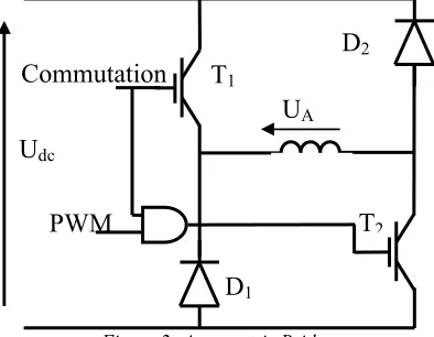
3. CONVERTER TOPOLOGY
The control of the SRM is performed by switching the supplied voltage between the three values Udc, -Udc and 0, from the continuous source. This source can be battery or generally an AC power supply with a rectifier and filter.
Figure 2: Asymmetric Bridge
[image:2.612.324.521.448.601.2]the soft switching strategy [12]. As the studied machine has four phase (MRV 8/6), the inverter will contain four asymmetric bridges, one for each phase. IGBT will be used for the switches T1 and T2.
4. POSITION ESTIMATION METHOD
[image:3.612.326.522.303.559.2]In SRM a sensor is attached on the rotor to provide the rotor position, however its use will reduce the reliability of the system and will increase the cost and size. Why it is important to use a method of estimating position. Compared with other methods of position estimation, the Current Sensor Gradient Method (CGSM) does not require knowledge of the magnetic characteristics. It uses the change of the current slope, in the position of the beginning of overlap between the rotor pole and stator pole, to estimate this position θe Figure 3.
Figure 3: Current waveform and its relationship to rotor position
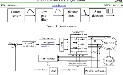
The operating principle of the CGSM is that the current slope becomes zero in the position θe where the inductance starts to increase. The position detection system shown in Figure 13 contains for each phase a current sensor, two low-pass filters of 2nd order to eliminate the switching frequencies and noise, a differentiator to get the slope of the current di/dt and finally a zero detector for detecting the annulment of the slope, that is the position to estimate. The current of the line Ibus contains all information of the four phase currents. Thanks to its use, the components in the detection system will be reduced.
The CGSM can estimate one position per stroke. The stroke in degree is given by:
r
N m× =
∆θ 360 (8)
Where Nr and m are the number of rotor poles and number of phases, respectively. For SRM 8/6 the stroke in degree is 15°.
5. THE FUZZY-PI CONTROLLER
5.1 System Identification and PI controller
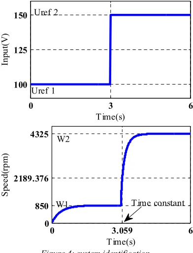
There are various methods to get the transfer function of SRM, in order to have optimum modeling. In this paper, we use the system identification method to find the transfer function of the SRM. This is the most practical method, and as the CGSM, used in this article to estimate the position, does not require knowledge of the SRM parameters, it consists of supplying the SRM with Uref step set-point. And from the response we identify the transfer function parameters of the system.
0 3 6
100 125 150
T ime(s)
In
p
u
t(
V
)
Uref 1 Uref 2
3.059
0 6
0 4325
2189.376
850
T ime(s)
S
p
e
e
d
(r
p
m
)
W2
W1 T ime constant
Figure 4: system identification
From the response shown in Figure 4, the SRM transfer function approximated by the identification method is first order and is written:
s K s V
s s H
. 1 ) (
) ( ) (
τ ω
+ =
= (9)
With τ, the instant that the response is equal to 63% of the final value and equal to 59ms. K is the ratio between the final value of the response and the amplitude of the input echelon of the identification method and equal to 18.66.
The error between the estimated speed and the reference speed is corrected with a PI controller. It is chosen to reduce the static error
L
aL
uCurrent
θ
eDetection signal of
the position
[image:3.612.92.283.330.488.2]and to improve the speed and reduce the overshoot. Its function is as follows:
s K K s
G i
P+ =
)
( (10)
With Kp=01072 and Ki=1.1866.
However, the standard PI controller has major disadvantages under load variation and mechanical motor parameters uncertainty, hence the need for an adapted PI controller, which will size with fuzzy logic method.
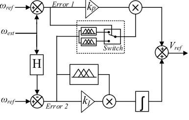
5.2 FUZZY-PI controller
A fuzzy logic algorithm is associated with a standard PI controller to achieve a FUZZY-PI corrector, it ‘is a non-linear controller with adjustable gains and designated for 25% of the rated load.
k
pʃ
H
ωref
ωref
ωest
Vref
+ +
-+ +
k
I Error 1Error 2
[image:4.612.288.505.75.320.2]Switch
Figure 5: Fuzzy-PI controller structure
The role of FUZZY-PI controller is to compensate the error between the reference speed and the measured speed (estimated) “error 1” and compensate the error between the reference speed and the desired speed profile “error 2”. These two errors are simulated respectively as the entry of the proportional gain and integral gain, these gains each have an output calculated with a special process.
Zone 1
Reference-speed
Time Speed
Zone 2
State 1
Zone1: ∆W>0, Ki
↗
and Kp↘
Zone2: ∆W>0, Ki
↗
and Kp↗
Reference-speed
Time Speed
Zone 1
Zone 2
[image:4.612.97.290.299.422.2]State 2
Figure 6: the proposed Fuzzy-PI controller
input
Output_Kp1
--
-
0
+
++
d--
d- d0
d+ d++
principle
Output_Kp1
X
0,5 0,75 1
d--
d- d0
d+ d++
1,25 1,5
Yi
Under
speed_ref
Output_Kp2
X
0,5 0,75 1
-
d-d0
d+
d++
1,25 1,5
Yi
input
Output_Kp2
--
-
0
+
++
-
d-d0
d+
d++
principle
Over
Speed_ferinput
Output_Ki
--
-
0
+
++
D’0 D’+ D’++
D’+
D’++
principle
X
0 1
Output_Ki
D’0
D’+ D’++
2,5 4
[image:5.612.89.531.68.581.2]Yi
Figure 7: Fuzzy Logic algorithm components: fuzzy sets for the outputs, the resulting control surface and
principle
6. SIMULATION AND RESULTS
The proposed algorithm was validated by simulation using Matlab/Simulink®, the simulation schema is shown in Figure 14. It contains a SRM 8/6. Its parameters and other configuration requirements are presented in Table I, it is controlled in a closed-loop speed, the speed is estimated with the current gradient slope method by estimating the position. The error between the reference speed and the
estimated speed is corrected with the FUZZY-PI controller. Its output signal is compared with a PWM signal in order to control asymmetric bridge converter to supply the four SRM phases.
Table 1: SIMULATION PARAMETERS
Components Name Values
R Stator resistance 0.05 Ω J Inertia 0.002 Kg.m² B Friction 0.005 N.m.s
Ls
Unaligned
inductance 0.67 mH
Tem
Aligned
inductance 23.6 mH
VDC DC-voltage 240 V
Ns
Number of stator
Poles 8
Nr
Number of rotor
Poles 6
ω Rated speed 3000 rpm
T Rated torque 5.2 N.m
FPWM PWM frequency 10kHz
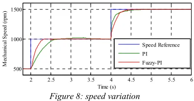
The proposed Fuzzy-PI controller was compared to the PI controller by simulation in different test. In the first test, we vary the reference speed; the results are shown in Figure 8.
2 2.5 3 3.5 4 4.5 5 5.5 6
1500
500 1000
Time (s)
M
ec
h
a
n
ic
a
l
S
p
e
ed
(
rp
m
)
Speed Reference PI
[image:5.612.326.524.408.511.2]Fuzzy-PI
Figure 8: speed variation
From figure 8, we note that when the PI controller is used the speed presents overshot caused by the over sizing. On the other hand, when the Fuzzy-PI controller is used the overshot disappeared.
[image:5.612.97.291.417.553.2]2 2.5 3 3.5 4 4.5 5 800 900 1000 1100 1200
Time (s) (a)
S p e e d ( rp m ) Spedd reference PI FUZZY-PI
2 2.5 3 3.5 4 4.5 5
800 900 1000 1100 1200
Time (s) (b)
[image:6.612.80.532.41.727.2]S p e e d ( rp m ) Speed reference PI FUZZY-PI
[image:6.612.319.522.77.373.2]Figure 9: Disturbances rejection response (a) 50% rated torque added, (b) 80% rated torque added
Table 2: Contrroler Performances Under Load Disturbances
Load 50% rated torque added
80% rated torque added
99% (s) Overs-
hot %
99% (s)
Overs-hot %
PI 0.443 6.5 0.65 18
Fuzzy-PI
0.05 4.3 0.05 9.7
it’s remarked that the response of the Fuzzy-PI controller was fast as much as the deference between reference and estimated speeds, Consequently, the load disturbance rejection has been done rapidly to preserve dynamic performances with the proposed controller unlike classic control with PI controller. Speed quantitative performances for this test are summarized in Table.2.
In this test, we will compare our algorithm with and without saturation block to show its importance in protecting the machine. We vary the reference speed from 200 to 1000 rpm with a load torque 4N.m; we observe speed, and the sum of the four currents in the machine.
From Figure 10, it is observed that adding the saturation block makes the speed response slower. However, the current of the machine does not exceed the set protection.
1.6 2 2.4 2.8 3.2 3.6
200 500 1000 Time (s) S p e d d ( rp m ) Speed ref
Speed without saturation bloc
Speed with saturation bloc
1.6
1.6 2 2.4 2.8 3.2 3.6
0 15 5 25 35 Time (s) C u rr e n t (A )
Current sum without saturation
1.6 2 2.4 2.8 3.2 3.6
0 8 15 25 35 Time (s) C u rr e n t (A )
Current sum with saturation
Figure 10: Comparison with and without saturation block with variable speed
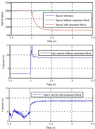
In the fourth test, the reference speed is fixed at 2000rpm, the load torque is 80% of the nominal value and it will be raised by the same value.
1.5 2 2.5 3 3.5
500 1000 1500 2000 2500 Time (s) S p e e d ( rp m ) Speed reference
Speed without saturation block
Speed with saturation block
1.5 2 2.5 3 3.5
3 6 10 13 Time (s) C u rr e n t (A
) Sum current without saturation block
1.5 2 2.5 3 3.5
3 6 10 13 Time (s) C u rr e n t (A )
Sum Current with saturation block
[image:6.612.325.525.424.695.2]From Figure 11, the algorithm without saturation block keeps the machine speed constant, but with a very large current. In practice, this current can destroy the SRM windings. However, the algorithm with the saturation block protects the machine by limiting the current to the maximum supported value.
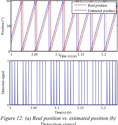
The last test is performed with and without a position sensor to validate the performance of the current gradient slope method. The reference speed and the load torque are fixed respectively to 2000rpm and 2N.m.
3 3.05 3.1 3.15 3.2
0 30 60
Time (s) (a)
P
o
si
ti
o
n
(
°)
Real position Estimated position
3 3.05 3.1 3.15 3.2
0 1
Time(s) (b)
D
et
e
c
ti
o
n
s
ig
n
a
l
Figure 12: (a) Real position vs. estimated position (b) Detection signal
From Figure 12 we see that the error is small between the real position and the estimated position. It is about 4°. At a stroke, we have four detection pulsations, one for each current of the four SRM windings. The major disadvantage of the CGSM is the need for a startup system.
7. CONCLUSION
In this paper, the proposed Fuzzy-PI controller has been studied and compared to classic PI controller by simulation, in which they were applied to sensorless control of switched reluctance motor. The position estimation is achieved through the current gradient slope method, this method allowed us to estimate the position and speed without the knowledge of the magnetic characteristic of the motor, only with the current profile. Its major disadvantage is the need for a startup system. Numerous tests are simulated, such as speed tracking, disturbance rejection capabilities and adaptive control of the controller. It was proved through simulation that the proposed algorithm was reliable under
various load torque profiles, such as torque variation and linear torque. In addition, it presents a high load disturbance rejection. As the algorithm does not contain a current loop, we realized a saturation block to protect the motor at high currents and destructive loads.
REFRENCES:
[1] R. Krishnan Switched Reluctance Motor Drives, CRC Press, 2001.
[2] T.J.E. Miller Switched Reluctance Motors and Their Control, Clarendon Press, Oxford, 1993.
[3] Boldea, "Control issues in adjustable speed drives", IEEE Industrial Electronics Magazinr. VoI.2, issue.3, sep 2008.
[4] G. G. Lopez , P. C. Kzaer and T. J. E. Miller "A New Sensorless Method for Switched Reluctance Motor Drives", IEEE Transaction on Industry Applications, vol. 34, no. 4, 1998, pp.832 -840.
[5] Won-Sik Baik; Min-Huei Kim; Nam-Hun Kim; Dong-Hee Kim; Kyeong-Ho Choi; Don-Ha Hwang; Jung-Soo Jang "Improved rotor position estimation for the sensorless control system of SRM", Industrial Electronics, 2005. ISIE 2005. Proceedings of the IEEE International Symposium on, vol. 3, 20-23 June 2005, On page(s): 877 – 880. [6] T. S. Radwan, NI. Nasir Uddin, and M. A.
Rahman, A New and Simple Structure of Fuzzy Logic Based Indirect Field Oriented Control of Induction Motor Drives, 2004 351h Annul IEEE Power Electronics Specialis1.r Conference Aachen, Germany. 2W4.
[7] Shady M. Gadoue, D. Giaouris, and J.W. Finch, “Genetic Algorithm Optimized PI and Fuzzy Sliding Mode Speed Control for DTC Drives”, Proceedings of the World Congress on Engineering 2007 Vol. 1 WCE 2007, July 2-4, 2007, London, U.K.
[8] L. Mokrani, R. Abdessemed, “A Fuzzy Self-Tuning PI Controller for Speed Control of Induction Motor Drive”, Proceedings of 2003 IEEE Conference on Control Applications, vol. 2, 2003, on page 785-790.
[image:7.612.91.290.234.445.2]Technology Vol. 4, No. 4, 2009, pp. 499-509.
[10] P. Lopez, A. S. Nouri, “Théorie élémentaire et pratique de la commande par les régimes glissants” mathématiques & applications 55, [11] S. Sadeghi, J. Milimonfared, M. Mirsalim,
M. Jalalifar: Dynamic Modeling and Simulation of a Switched Reluctance Motor in Electric Vehicle, Proc ICIEA Conf, 2006. [12] Do-Hyun Jang; "The converter topology
Figure 13: Detection system
Fuzzy-PI controller
Position Estimator SRM 8/6
d/dt
Phase selector Anti-windup
ISat
VM ax
Vmi n PW
M
Load
ωref
ωest
Estimated speed Estimated postition
Ia IbIcId
-+
Converter
Saturation
Figure 14: Overall block diagram of the proposed control system