MONITORS
Programmer's Reference Manual
System
ADVANCED Software
Order No. DEC-9A-MABO-D from Program Library, Maynard, Mass. Price $2.00
()riginal Printing March 1967 Rev ised February 1968
Chapter
1.1
1.2
1.3
1. 3. 1
1 .3.2
1
.3.3
1.4
1 .4. 1
1
.4.2
1
.4.3
1.4.4
1 .4.5
1 .4.6
1.4.7
1
.4.8
1
.4.9
1.4.10
2.
2. 12.1.1
2.1.2
2.1 .3
2.2
2.2.1
2.2.2
2.3
2.4·
2.4.1
2.4.2
2.4.3
CONTENTSPDP-9 ADVANCED SOFTWARE SYSTEM •••••••••••••••.••••••••••••••••
Introduction .•..•...••...•.••....•...•...•.
Hardware Requirements •••••••••••••••••••••••••••.•••••••••••••••
Monitor Systems . . . .
Input/Output Monitor . . . .
Keyboard Mon i tor .••••••••••••... ~ ••••••••••.••••.•••••••••.
Input/Output Programming System (lOPS) •••••••••••••••••••••••
System Programs .••.•.•.•.•.•.•••.•.••..••••••.•.••.••••••..•...•
FORTRAN IV ••••••••••••••.••••••••••••••••••••••••..•.••••
Macro Assembler (MACRO-9) .••••••••••••••••••••••••••••••••
Debugging System (DDT -9) ••.••••••••••••••••••••••••••••••••
Text Editor (EDIT-9) .•.••••••••••••••••••••••••••••••••••
Peripheral Interchange Program (PIP-9) ••••••••••••••••••.••••••
Linking Loader (LINK-9) •••••••••••••••••••••••••••••••••••••
PDP-7 Assembly Language to MACRO-9 Assembly
Language Converter (CONV -9) ••••••••••••••••••••••••.••••••
System Generator (S GE N-9) .•••••••••••••••.••••••••••••••••••
DUMP (DUMP-9) ...••...
Library Update (UPDATE-9) .•••.•.••••••••••••••••••••••••••••
INPUT/OUTPUT MONITOR SYSTEM •••••••••••••••••••••••••••••••••••
Input/Output Monitor Functions •••••••••••••••••••••••••••••••••••
Data Transmission Paths ••••••••••••••••••••••••••••••••••••••
Dcta Modes . . . • . . . • • . . . • . . . . • . . . • . . . •
Device Assignment Tables ••••••••••••••••••••••••••••••••••••
User Program Commands .•••••••••••••••••••••••••••••••••••••••••
General Commands ••••••••••••••••••••••••••••••••••••••••••
Mass Storage Device Commands .••••••••.•••••••••••••••••••••
Device Assignments . . . • . . . • . . .
Programm i ng wi th User Program Commands .••.••••••••••••••••••••••
Defining Line Buffers ...•...•...•...•....•.•.
Specifying Devices Used to the Linking Loader .••.••••••.•.•••.•
Using Program Commands with MACRO-9 .••••••••••••••••••••••
Chapter 2.5 2.5.1 2.5.2 2.5.3 2.5.4 2.5.5 2.5.6 2.5.7 2.6
3
3. 1
3.1.1 3.1 .2 3.2 3.2.1 3.2.2 3.2.33.3
3.4 3.4.1 3.4.2 3.4.3 3.4.4 3.4.54
4. 1
4.2 4.34.4
4.5 4.6 4.6.1 4.6.2CON TEN T S (continued)
Loading Programs with the I/O Monitor .••...••••..•••.•••••..••.••.
FORTRAN IV Compi ler .•.•.•.•••••••.••••••••.••••••••••••••.
Macro Assembler (MACRO-9) .••••••••••••••••••••••••••••••••
PIP-9 (Peripheral Interchange Program) .••••••.•••.•••••.•••••••
Text Editor (EDIT-9) .•••..•••.•.•••••••••••••••••••••••••••
Linking Loader (LINK-9) .••.•.•••••••••••••••.••••••••••••••.
DDT -9 ...•...
7 -to-9 Converter ••....•.•.••.•••.•••••.•...•.•.••...•..•....
Error Detection arid Handling .•••.••••••••••••••••••••.•••••.•••••
KEYBOARD MONITOR SYSTEM .••.•.••••••••••••••••.••••••••••••••••
Keyboard Monitor Func ti ons ....•••••••.•••••••••••.••••••••••••••
System Device and Bootstrap •••.••••••••••••••••••••••••••••••
Keyboard Monitor Structure .••.•••.•••••••••••.•••••••••••••••
Keyboard Commands .•••••.••••••..•.•••••••••••.••••..••.•••••••
Device Examination, Assignment, and Information Commands •..••.
Loading System Programs .••.•.•••••••••••••••••••••••••••••••
Other Keyboard Commands .••••••••••••••••••••••••••••••••••
Programm i ng for Device Independence .••••.••••••••••••••••••••••••
Operating the Keyboard Monitor System .•••••••••••••••••••••••••••
Loading the Monitor . . . • . . System Generation . . . .
Assign ing Devices . . . • . . .
Loading Via Console Commands .••••.•.•••.••••••••••••••..•••
Error Detection and Handling ••••••••.••••••••.•••••••••••••••
SUMMARY OF COMMANDS ••.••••••••••.•••••••••••••••••••••••••••
Summary of User Program Commands .•••••••••••••••••••••••••••••••
System Communication Table (.SCOM) ••.••••••••••••••••••••••••••
Maximum Line Buffer Sizes (Including 2-Word Header) ••.••.•••••.••••
Summary of Keyboard Commands ...••.•••••••••••.•••••••••••••••••
Monitor/lOPS Command Table .••••••••••••••••.••••••••••.••.••••
Summary of Standard I/O Handler Features ••.••••••••••••••.•.•.•.••
LPA (647 Line Printer) •••••••••••••••••••••••••••••••••••••••
TTA (TELETYPE) •••••••.••••••••••••••••••••••••••••••••••••.
Chapter 4.6.3 4.6.4 4.6.5 4.6.6 4.6.7 4.6.8 4.6.9 4.6.10 4.7 4.7. 1
[image:6.612.94.570.75.644.2]4.7.2
4.7.3 A-1 A-2 Figure 2-1 2-2 2-32-4
2-5 3-1 3-2 3-3 3-4 4-1 4-2CON TEN T S (continued)
PP (PAPER TAPE PUNCH) .• 0 • • • 0 • • • • • • • • • • • • • • • 0 • • 0 • • • • • • • • • • •
PR (P APER TAPE READER) •••..••••• 0 • • • • • • • • • • • • • • • • • • • • • • • 0 • •
DT (DECT APE) • 0 • • • • • • • • 0 o • • • • • • • • • • 0 • • • • • • • • • 0 ' • • • • • • • • • • • •
CD (Card Readers) .•••• o • • • • 0 ' • 0 • • • • • • 0 • • • 0 ' • • • 0 0 • • • • • • • • • • • •
MT (Magnetic Tape) .•.••••••• 0 • • • • • • • • • • • • • • o • • 0 0 • • 0 • • • • • 0 ' •
DK (Disk) ...•...•...
DR {Drum} ...•....•.•....•...•.•...•...•.
I/O Handlers Acceptable to System Programs •••••••••• 0 • • • • • • • 0 •
Description of I/O Hardware and API Software Level Handlers •••••••••
110 Dev i ce Hand lers .•..•.•..•••••••••••••••••••..•.•.••••••
API Software Leve I Handlers ••.••.•• 0 • • • • • • • • • • • 0 • • • • • • • • • 0 • • •
Standard API Channel/Priority Assignments .••••••••••••••• 0 • • • • •
PDP-9 ASCII/HOLLERITH CORRESPONDENCE .•••••••••• 0 0 • • 0 • • • • 0 • 0 . 0 .
PDP-9 ASCII CHARACTER SET .••.•••••••••••••••••••••••••••••••••••••
ILLUSTRATIONS
Line Buffer Structure •••••••••.••.••••.•••••••••••••••.•••.•.••••••••• Format of Header Word Pair.o 0 • • • • • • • • • • • • • 0 • • • • 0 • • • • • • • • • • • • • • • • • • • • •
5/7 ASCII Packing Scheme •••.•....•...•.•.•..••.•••.•.•.••....••.• 0
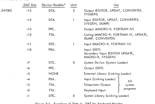
Device Assignment Table for I/O Monitor •••••••••••••••.••.•••.•.••••• Library File Structure •..•.•••••••.••••.•••••••••••.••....••••••••.••• Function of Slots in • OAT for Keyboard Mon itor ••••...••..•.•••••.••.•• 0
Library File Structure •..•.••.•.•..••••.••.••••..•..•••.•..•.•.•••• ~ •• Memory Maps: Bu Ik Storage Systems •.•••.••••••.•••.••••••.•••••....••• Paper Tape System (I/O Mon itor) •...••••••••..••••.•.•...•.•.••.••• lOPS Binary Inpyt Card Format •••.•..••..•.••.••.•••.••..•.••.•.•..••• Structure of API Software Level Handler ••••••••••.••••...•.•.•.•
PREFACE
This Monitor programmer's reference manual contains information needed to prepare programs
for operation in the PDP-9 ADVANCED Software System. Both the I/O Monitor (paper tape systems)
and the Keyboard Monitor (bulk storage systems) are described.
Chapter 2 contains information essential to programming both Monitors. The following topics
should be studied carefully by all PDP-9 programmers:
a. Data flow in and out of the user's program, inc luding avai lable data modes (ASCII,
binary, etc.) and device assignment tables, which provide the linkage between the user
program and the supplied device handlers.
b. System I/O macros to perform all I/O functions. Format and use of each instruction
is explained.
c. Line buffers, through which all data passes between the user's program and the
various I/O devices. Buffer headers and standard sizes are discussed.
d. Examples of buffers and some typical input/output operations using system macros.
For the convenience of PDP-9 ADVANCED Software System programmers, a new operating
guide for users of paper tape systems, prepared especially for use at the computer console, is now
available. This manual is called "1/0 Monitor Guide" (Paper Tape Systems) Order Number
DEC-9T-NGAA-D. The I/O Monitor Guide contains all of the essential information needed to operate the
CHAPTER 1
PDP-9 ADVANCED SOFTWARE SYSTEM
1 . 1 INTRODUCTION
PDP-9 ADVANCED software provides a complete system for program preparation, compilation,
assembly, debugging, and operation. It features total relocatabi
I
ity and can expand to take fullad-vantage of any hardware configuration. Powerful system programs include FORTRAN IV, a sophisticated
macro assembler, an on-line debugging system, an on-line editor, and a peripheral interchange
pro-gram. A versatile and flexible input/output programming system frees the user from the need to create
device-handl ing subroutines and the concerns of device timing.
Two monitor systems are avai lable with PDP-9 ADVANCED software. The Input/Output
Monitor operates on a basic PDP-9 with 8, 192 (or more) words of memory, high-speed paper tape reader
and punch, and a console teleprinter. The I/O Monitor operates in a paper tape (or card) environment
and provides for the calling and handling of all input and output functions.
A more sophisticated Keyboard Monitor is available for systems with bulk auxiliary-storage
units. It allows for device-independent programming and automatic creation, calling, and loading of
programs. Since the Input/Output Monitor is a subset of the Keyboard Monitor, all programs prepared
for use with it can be run on the more sophisticated system.
1.2 HARDWARE REQUIREMENTS
To operate the PDP-9 ADVANCED software system under control of the Input/Output Monitor,
a basic PDP-9 is required with:
a .
8,
192 words of core memoryb. 300 c haracter-per-second paper tape reader
c. 50 character-per-second paper tape punch
d. Console teleprinter (Teletype Model KSR 33 or KSR 35)
Extra memory, the Type KE09A Extended Arithmetic Element and the Type KF09A Automatic
Priority Interrupt, if present, can also be utilized by this system. A card reader, Type CR02B, can be
used for input in addition to the paper tape reader, and a Type 647 Line Printer can be used for listings.
To utilize the Keyboard Monitor, some form of bulk storage must be added to the basic PDP-9:
a. Type TC02 DECtape Control and two Type TU55 DECtape Transports.
b. Type TC59 Magnetic Tape Control and two 7-channel or 9-channel Magnetic Tape
Transports (Type TU20, Type TU20A, or equivalent).
c. Type RM09 Block Transfer Drum System
d. Type RC09 Fixed-Head Disk System
This system, too, can take full advantage of extra memory, central processor options, and
additiona
I
i nput/ output options.1 .3 MONITOR SYSTEMS
PDP-9 ADVANCED software monitor systems exist to simplify the handling of input/output
functions and to facilitate the creation, debugging, and use of PDP-9 programs. They allow overlapped
input/output and computation, simultaneous operation of a number of asynchron()us peripheral devices,
and (in the case of the Keyboard Monitor) device-independent programming -- (JII while freeing the
user from the need to create device handl ing subroutines. The Monitors, operating in con junction with
the Input/Output Programming System (lOPS), provide a complete interface between the user's programs
and the peripheral hardware.
1 .3. 1 Input/Output Monitor
The Input/Output Monitor accepts I/O commands from the system or IJser programs and
super-vises their execution. By call ing upon the device manipulation routines of lOPS, it can allow simultaneous
I/O and computation.
1.3.2
The I/O Monitor contains:
a. Routines for its own initialization and control.
b. Tables to allow communication between the Monitor, system programs, user
pro-grams, and the Input/Output Programming System.
c. The CAL Handler, which is used to dispatch to the approprklte Monitor subroutines.
d. Device handlers for the Teletype and clock.
The I/O Monitor resides in lower core and occupies about 775
10 loccltions.
Keyboard Mon itor
The Keyboard Monitor is designed to operate on a PDP-9 system with some form of auxil iary
bulk storage (see Hardware Requirements, Section 1.2). It includes all of the fOlcilities of the I/O
Monitor plus routines to accept and act upon keyboard commands, the ability to dynamically modify
I/O device assignments for a program, and the facilities for automatically storing, calling, loading,
and executing system and user programs.
With the ability to alter I/O assignments, the Keyboard Monitor brings to the user true device
independence. Programs may be swiftly and simply modified to operate on any configuration, and
ad-ditions to (or deletions from) an existing system need not result in program reassembly or recompilation.
The Keyboard Monitor also frees the user from the problems of tape or card handling. At the
keyboard console, programs can be created, stored, retrieved, loaded, debugged, and operated. Both
1 .3.3 Input/Output Programming System (lOPS)
The Input/Output Programming System (lOPS) consists of an I/O control routine (basically a
CAL handler) and individual hardware device handling subroutines which process fi Ie and data level commands to the devices. These handlers exist for all standard PDP-9 peripherals (see Section 4.6).
The I/O control routine accepts user program commands and transfers control torhe
appropri-ate device handlers. These device handlers are responsible for transferring data between the program
and I/O devices, for initiating the reading or writing of files, for the opening and closing of files, and
for the performance of all other functions pecu liar to a given hardware device. They are also
respons-ible for ignoring functions of which they are incapable (e.g., trying to rewind a card reader or skipping
files on a non-file-oriented device). All device handlers will operate with or without the automatic
priority interrupt (API) option.
1
.4
SYSTEM PROGRAMSPDP-9 ADVANCED software systems include either the Input/Output Monitor (basic systems)
or the Keyboard Monitor (bulk storage systems), the Input/Output Programming System, and the
follow-i ng system programs:
a. FORTRAN IV Compiler, Operating System, and Library.
b. Macro Assembler (MACRO-9)
c. Debugging System (DDT -9)
d. Text Editor (EDIT -9)
e. Peripheral Interchange Program (PIP-9)
f. Linking Loader (LIN K-9)
g. PDP-7 Assembly Language to MACRO-9 Assembly Language Converter (CONV-9)
h. System Generator (SGE N-9) }
i. DUMP (DUMP-9) With Keyboard Monitor system only
j. Library Update (UPDATE-9)
A brief introduction to each is given below.
1 .4. 1 FORTRAN IV
The PDP-9 FORTRAN IV compiler is a two-pass system which accepts statements written in
the FORTRAN IV language and produces a relocatable object code capable of being loaded by the
Linking Loader. It is completely compatible with USA FORTRAN IV, as defined in USA Standard
X3.9-1966, with the exception of the following features which were modified to allow the compi ler to
a. Complex arithmetic wi
II
not be avai lable.b. Adjustable array dimensions will not be allowed.
c. Blank Common will be treated as named Common.
d. The implied DO feature will be deleted from the DATA statement.
e. Spec ification statements must be strictly positioned and ordered.
This FORTRAN IV compiler operates with the PDP-9 program interrupt facility enabled. It
generates programs that operate with the program interrupt enabled and can work in conjunction with
assembly language programs that recognize and service real-time de'.ti(;~~s. Subroutines written in either
FORTRAN IV or MACRO-9 assembly language can be loaded with and called by FORTRAN IV main
programs. Comprehensive source-language diagnostics are produced during compi lation, and a symbol
table is generated for use in on-line debugging with DDT -9.
PDP-9 FORTRAN IV is described fully in the PDP-9 ADVANCED Software FORTRAN IV
Manual (DEC-9A-AF40-D).
1 .4.2
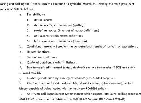
Macro Assembler (MACRO-9)With the Macro Assembler, PDP-9 users are able to utilize highly sophisticated macro
gen-erating and calling facilities within the context of a symbolic assembler. Among the more prominent
features of MACRO-9 are:
a. The abil ity to
1 • defi ne macros
2. define macros within macros (nesting)
3. re-define macros (in or out of macro aefinitions)
4. call macros within macro definitions
5. have macros call themselves (recursion)
b. Conditional assembly based on the computational results of symbols or expressions.
c. Repeat functions.
d. Boolean manipulation.
e. Optional octal and symbolic listings.
f. Two forms of radix control (octal, decimal) and two text modes (ASCII and 6-bit trimmed ASCII).
g. Global symbols for easy linking of separately assembled programs.
h. Choice of output format: relocatable, absolute binary (check summed); or full
binary capable of being loaded via the hardware READIN switch.
i.
Ability to call input/output system macros which expand into lOPS calling sequences. [image:13.615.44.533.373.728.2]1 .4.3 Debugging System (DDT -9)
DDT-9 provides on-line debugging facilities within the PDP-9 ADVANCED software system.
With it, the user may load and operate his program in a real-time environment while maintaining strict
control over the running of each section. DDT -9 allows the operator to insert and delete breakpoints,
examine and change registers, patch programs, and search for specific constants or word formats.
The DDT -9 breakpoint feature allows for the insertion and simultaneous use of up to four
break-points, and anyone or all of which may be removed with a single keyboard command. The search
facility allows the operator to specify a search through any part 'of all of an object program with
print-out of the locations of all registers that are equal (or unequal) to a spec ified constant. This search
feature also works for portions of words as modified by a mask. With DDT -9, registers may be examined
and modified in either instruction format or octal code, and addresses may be specified in symbolic
rel-ative, octal relrel-ative, or octal absolute. Patches may be inserted in either source language or octal.
DDT-9 is described more f':Jlly in the PDP-9 Utility Programs Manual (DEC-9A-GUAB-D).
1
.4.4 Text Editor (EDIT -9)The Text Editor of the PDP-9 ADVANCED software system provides the ability to read
alpha-numeric text from any input device (paper tape reader, card reader, disk, drum, DECtape, magnetic
tape, etc.), to examine and correct it, and to write it on any output device. It can also be used to
creat~ new symbol ic programs.
The Editor operates on lines of symbolic text delimited by carriage return (CR) characters.
These
I
ines can be read into a buffer, selectively examined, deleted or modified, and written out. Newtext may be substituted, inserted, or appended.
For further details of EDIT-9 see PDP-9 Utility Programs Manual (DEC-9A-GUAB-D).
1 .4.5 Peripheral Interchange Program (PIP-9)
The primary function of PIP-9 is to facilitate the manipulation and transfer of data files from
any input device to any output device. It can be used to update file descriptions, delete, insert, or
combine fi les, perform code conversions, and rewind tapes.
Directions for the use of PIP-9 can be found in the PDP-9 Utility Programs Manual
(DEC-9A-GUAB-D).
1 .4.6 Linking Loader (UNK-9)
The Linking Loader loads any PDP-9 FORTRAN IV or MACRO-9 object program which exists
called subroutines, retrieval and loading of implied subroutines and lOPS routines, and building and
re location of the necessary symbol tables. Its operation is di scussed in the PDP-9 Uti I ity Program
Manual (DEC-9A-GUAB-D).
1 .4.7 PDP-7 Assembly Language to MACRO-9 Assembly Language Converter (CONV-9)
This system program converts source programs written in PDP-7 or basic PDP-9 assembly
lung-uage to a format acceptable to the MACRO-9 assembler.
CONV-9 is described more fully in the PDP-9 Utility Programs Manucd (DEC-9A-GUAB-D).
1 .4.8 System Generator (SGEN-9)
The System Generator is a standard system program used to create new system tapes. With it,
the user can tai lor his system to his installation's needs and spec ify standard inpul" and output devices,
memory size, and special I/O and central processor options present. A more complete description of
SGEN-9, and details of its use, are given in Section 3.4.4.7.
1.4.9 DUMP (DUMP-9)
This system program gives the user the ability to output on any listing device specified core
locations that had been preserved on a bulk storage file via the tQ (control key/Q) monitor dump
com-mand (see Section 3.2.3.5).
1 .4. 10 Library Update (UPDATE-9)
This system program gives the user the capability to examine and updaj"e the library files on
file-oriented devices. A more complete description of UPDATE-9, and details of its use, are given in
, CHAPTER 2
INPUT/OUTPUT MONITOR (Paper Tape Systems)
2.1 INPUT/OUTPUT MONITOR .. FUNCTIONS
The I/O Monitor of the PDP-9 ADVANCED software system simplifies the programming of
input and output functions and allows programs to operate, without modifications, in both the Keyboard
Monitor environment and the basic paper-tape' environment. It serves as an interface between the
system and user programs and the external world of device hardware, drawing upon the routines and
capabilities of the Input/Output Programming System (lOPS) to relieve the programmer of writing his
own device and data handling subroutines. The I/O Monitor allows simultaneous operation of many I/O
peripherals and overlapped computation.
The Input/Output Monitor is designed to take advantage of the automatic priority interrupt
(API) if it is present on the system. Both the I/O skip chain for the program interrupt control (PIC) and
the API channels are set up to handle all devices which have been requested by the user. All unused
channels are tied to an error routine to detect spurious interrupts.
2.1.1 Data Transmission Paths
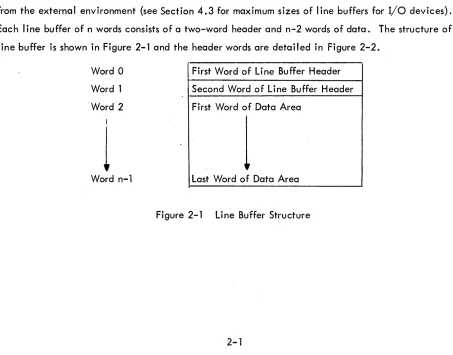
Each system or user program must internally set up line buffers for data transmission to or
from the external environment (see Section 4.3 for maximum sizes of
I
ine buffers for I/O devices).Each
I
ine buffer of n words consists of a two-word header and n-2 words of data. The structure of aline buffer is shown in Figure 2-1 and the header words are detailed in Figure 2-2.
Word 0
Word 1
'Word 2
I
1
Word n-l
First Word of Line Buffer Header
Second Word of Line Buffer Header
First Word of Data Area
1
Last Word of Data Area
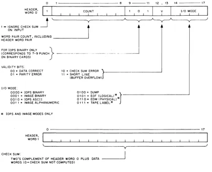
[image:16.612.96.549.399.754.2]HEADER, WORD 0
I = IGNORE CHECK SUM ON INPUT
o
WORD PAIR COUNT, INCLUDING HEADER WORD PAIR
FOR lOPS BINARY ONLY } (CORRESPONDS TO 7-9 PUNCH ON BINARY CARDS)
VALIDITY BITS:
00"' DATA CORRECT
01 = PARITY ERROR
I/O MODE:
0000" lOPS BINARY
000 I = IMAGE BINARY
0010= lOPS ASCII
00 I 1 .. IMAGE ALPHANUMERIC
*
lOPS AND IMAGE MODES ONLY- - - 8
10 = CHECK SUM ERROR
r
II = SHORT LINE(BUFFER OVERFLOW)
010 I = EOF (LOGICAL)
*
0100 = DUMP
J
011 0" EOM (PHYSICAL)
*
011 1 = TAPE LABEL
*
9 - - - 1 1
o
12 ,13 14 - - - 17
V I
I/O MODE I
0---17
CHECK SUM:
HEADER, WORD 1
TWO'S COMPLEMENT OF HEADER WORD 0 PLUS DATA WORDS (0= CHECK SUM NOT COMPUTED)
y
[image:17.613.73.493.171.511.2]For output, the program must set the appropriate word pair count in bits 1-8 of word 0 of the
I
ine buffer header. This count overrides, the one passed on to lOPS by the. WRITE command to theMon itor. In lOPS binary mode, bits 9-11 should be set to 101 to indicate binary mode if the output
de-vice is a card punch. The checksum word (header word 1) may be left blank,since checksums are
com-puted by lOPS.
For input, the user should check the validity bits (bits 12 and 13)of word 0 of the line buffer
header to determine if the data was read without error. (lOPS sets the appropriate bits if it senses an
error. If multiple errors are detected, priority will be given to parity error then to checksum error. It
wi
II
ignore checksum errors on binary input if bit 0 of word 0 of theI
ine buffer header, contained on the input medium, is set to 1.) lOPS will set the I/O mode bits (bits 14-17 of word 0 of the line bufferheader) to
6
(01102) if it senses a physical end-of-medium (such as end-of-tape in the paper-tape reader). The Monitor accepts commands from the system or user program to initiate input to the line
buffers and to write out the contents of the
I
ine buffers. A fuII I
ist of these commands is given inSec-tion 2.2.
2.1.2 Data Modes
The Input and Output Programming System (lOPS) will allow data transmission to or from a
PDP-9 ADVANCED software system program in one of five general forms:
Code
a. lOPS Binary Mode 0
b. Image Binary Mode 1
c. lOPS ASCII Mode 2
d. Image Alphanumeric Mode 3
e. Dump Mode 4
2.1.2.1 lOPS Modes - 7-bit ASCII is used throughout the lOPS system to accommodate the entire
128-character revised ASCII set. In lOPS ASCII, all alphanumeric data, whatever, its original form on
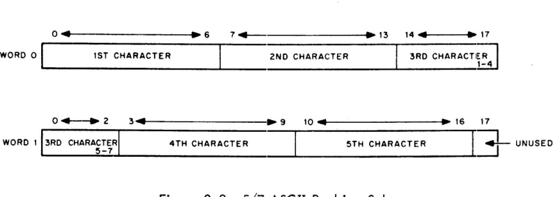
input (ASCII, Hollerith, etc.) or final form on output, is converted and stored as "5/7 ASCII."
5/7 ASCII refers to the internal packing and storage scheme for ASCII data. Five 7-bit
ASCII characters are packed into two consecutive 18-bit binary words, as shown in Figure 2-3. They
are stored as binary data on any bulk storage device.
It is recommended that a" input requests in lOPS ASCII mode be made with an even word
0 ... t---l.~6 7 + - .13 14" ~ 17
WORD 0 1ST CHARACTER 2ND CHARACTER 3RD CHARACTI;;l
~---~---~---~
o + - - . 2 3 ...
4 . - - - . 9
10 .. ~ 16 17WORD 113RD
CHARA~~~RI
4TH CHARACTER 5TH CHARACTER I ..l
UNUSEDFigure 2-3 5/7 ASCII Packing Scheme
ASCII data is input to or output from lOPS, ordinarily, via the TeletYlpe or paper tape,
al-though it may exist in 5/7 ASCII form on any mass storage device. lOPS ASCII is normally defined as
a 7-bit ASCII character with even parity in the eighth (high order) bit, in keeping with USA standards.
lOPS performs a parity check on input of lOPS ASCII data prior to the 5/7 packing. On output, lOPS
generates the correct parity. (See Appendices I, II.)
Non-lOPS ASCII occurs in data originating at a Model 33, 35, or 37 Teletype, without the
parity option. This data always appears with the eighth (high order) bit set to 1. Apart from parity
checking, the lOPS routines handle lOPS ASCII and non-lOPS ASCII data identically.
An alphanumeric line consists of an initial form control character, the body of the line, and
a carriage return (CR) or ALT mode. CR (or ALT mode) is a required line terminator in lOPS ASCII mode.
Control character scanning is performed for editing or control purposes (see Section 4.6 for affects of
control characters on specific devices).
lOPS Binary data is blocked in an even number of words, with each block preceded by a
two-word header. On paper tape, lOPS binary util izes six bits per frame, with the eighth channel always
set to 1, and the seventh channel containing the parity bit (odd parity) for the olrher seven channels.
The parity feature supplements the checksumming as a data validity provision in paper tape lOPS binary.
Mixed data {both 5/7 ASCII and lOPS Binary} can be accepted as input (generated as output)
by adjacent lOPS ASCII and lOPS binary ·READ's (.WRITE's.)
2. 1 .2.2 Dump Mode - Dump Mode data is always binary and is the mode used lro output from or load
directly into any core memory area, bypassing use of line buffers. Each dump mode statement has
argu-ments defining the core memory area to be dumped. Although dump mode is normally used with bulk
storage devices, it is also possible to use it with paper tape output and input.
2. 1 .2.3 Image Modes - Image Mode data is read, written, and stored in the binary or alphanumeric
form of the source or terminal device, one character per word. No conversion, checking, or packing
[image:19.612.77.474.71.213.2]2.1.3 Device Assignment Tables
Both FORTRAN and MACRO-9· coded user programs, as well as the system programs, specify
their input and output operations in terms of I/O commands to logical I/O units. One of the Monitor's
functions is relating logical units to actual hardware devices. To do so, the I/O Monitor contains a
device assignment table (. DAT) whose slot numbers correspond to logical I/O units.
Each. DAT slot referenced contains the device unit number (if applicable) and a pointer to
the device handler for this device (see Section 2.3 and Figure 2.4).
All communications between programs, their line buffers and the actual device handlers are
accomplished via. DAT slot numbers.
2.2 USER PROGRAM COMMANDS
Requests to the I/O Monitor for input or output functions are initiated by the system or user
programs. In FORTRAN IV, these requests are in the form of READ (u); WRITE (U}i READ (u, f)i and
WRITE (u, f) statements which are translated by the compiler into the proper calling sequences for the
FORTRAN Object-Time System. The FORTRAN Object-Time System, in turn, executes the required
Monitor calls. In MACRO-9, these requests are in the form of I/O macros which are written as part
of the program and which expand into the proper Monitor calling sequences.
User commands available in MACRO-9 programs include:
Name .
. INIT
. READ
. WRITE
• WAIT
.CLOSE
. TIMER
. EXIT
.SEEK
. ENTER
. CLEAR
. MTAPE
.TRAN
• DLETE
. RENAM
• FSTAT
Purpose
Initializes the device and device handler .
Transfers data from the device to the line buffer .
Transfers data from the I ine buffer to the device .
Detects avai lab i I ity of the user's I ine buffer .
Terminates use of a file.
Calls and util izes real-time clock .
Returns control to the Monitor .
Finds file on file-oriented device and begins data input.
Primes file-oriented device for file ou!put.
Initializes file structure on file-oriented device •
Provides special commands for IBM-compatible magnetic tape .
Reads or records user-specified blocks on bulk storage devices, providing the user with the capability to determine the structure of the fi les on the device.
Deletes file from file-oriented device .
Renames file on file-oriented device .
A complete discussion of these macros, and their expansions, is given in Sections 2.2.1 and 2.2.2.
2.2.1 General Commands
The following commands can be used on all devices, whether file-oriented or not.
2.2.1.1 .INIT (Initialize)
FORM: .INIT ... a, F, R
VARIABLES: a = Device Assignment Table (.DAT) slot number (in octal radix)
EXPANSION:
{
o
= Input Fi Ie
F
=
File Type: 1=
Output FileR
=
User Restart Address*LOC
LOC + 1
CAL + F 7-8 + a9-17
.1
LOC + 2 R
LOC + 3 n
/The CAL handller will place the unit /number (if applicable) associated with /. DAT slot ~ into bits 0-2 of this word. **
/Maximum size of line buffer associated /with • DAT slojt ~; i. e., 225
10 for DEC-/tape (see Section 4.2)***
DESCRIPTION: The macro .INIT causes the device and device handler associated with. DAT slot a
to be initialized • • INIT must be given prior to any I/O commands referencing .DAT slot~; a
separate.INIT command must be given for each. DAT slot referenced by the pr09ram. **** Since a
. DAT slot may refer to only one type of file (input or output), only one file type specification (0 or 1)
may be made in an .INIT statement. If a • DAT slot first references an input file, then an output file (or vice versa), a second. INIT command must be executed to change the transfer direction prior to
the actual data transfer command.
* Has meaning only for. INIT commands referencing slots used by Teletype (the last. INIT command en-countered for any slot referencing the keyboard or teleprinter takes precedence). When the user types tP, control is transferred to R. For example, the Linking Loader takes advantage of this feature to re-start the system when a new medium has been placed in the input device.
**Has no direct effect upon the user1s program, but should be noted so that no atl'empt will be made to use LOC + 1 as a constant.
***Size is returned by the handler so that the program, in a device-independent environment, can use it to properly set up I ine buffers.
2.2.1.2
.READFORM:
VARIABLES:
EXPANSION:
. READ ... a, M, L, W
a
= .
DAT slot number (octal radix)M = Data mode
L = Line bu ffer address
o
=
lOPS Binary 1=
Image Binary2
= lOPS ASCII3
=
Image Alphanumeric4
=
Dump ModeW = Line buffer word count (decimal radix), including the two-word header
LOC
LOC + 1
CAL + M
6_8 + a9--17 10
LOC + 2 L .DEC
LOC +
3
-W
/CAL Handler will place unit number /(if applicable) into bits 0-2.
/Decimal radix
DESCRIPTION: The. READ command is used to transfer the next
I
ine of data from the deviceassigned to • DAT slot ~ to the line buffer in the user's program. In this operation, M defines the
mode of the data to be transferred (see Section
2.
1.2
for a discussion of data modes); L is theaddress of the line buffer; and W is the count of the number of words in the line buffer ( including the
two-word header).
Since I/O operations and internal data transfers may proceed asynchronously with
computa-tion, a . WAIT command (see Section
2.2.·j .4)
must be used after a .READ command before the userattempts to use the data in the line buffer or to read another line into it.
When a . READ (non-dump mode) has been completed, the program should interrogate bits
12-13 of the first word of the I ine buffer header to ascertain that the line was read without error. Bits
14-17 should be checked for end-of-medium and end-of-file conditions.
2 . 2. 1 . 3
.
WR IT EFORM: .WRITE ... a, M, L, W
VARIABLES: a
=
.DAT slot number (octal radix)M = Data Mode
0= lOPS Binary 1
=
Image Binary 2 = lOPS ASCIIEXPANSION:
L = Line buffer address
W:::: Line buffer word count (decimal radix), includinSI the two-word header
LaC
LaC + 1
CAL + M
6_8 + a9-17 11
LaC + 2 L
.DEC
LaC + 3 -W
/The CAL Handler will place the unit /number (if applicable) associated with / . DAT slot ~ into bits 0-2
/Decimal radix
DESCRIPTION: • WRITE is used to transfer a line of data from the user's line buffer to the device
associated with. DAT slot a •
. WAIT must be used after a • WRITE command, before the I ine buffer is; used again, to insure
that the tranfer to the device has been completed.
Only in the lOPS binary mode are headers output with the data (bits 9 and 11 of header word
o
shou Id be set to 1). In image modes the header space cannot be used for data, even though the headersare not written out. The word pair count in the header takes precedence in all modes and must be
in-serted by the user.
For both • READ and • WRITE macros, dump mode causes the transfer of the spec ified core
area to or from one record on magnetic or paper tape. One or more blocks on DECtape, disc or drum
may be occupied by a single dump command. A subsequent. WRITE in DUMP mode will utilize the
un-fi II ed portion of the last block.
2.2.1.4 . WAIT
FORM: • WAIT ' - I a
VARIABLES:
EXPANSION:
a = • DAT s lot number (octal radix)
LaC
LaC + 1
CAL + a 9-17
12 /The CAL Handler will place the unit
/number (if applicable) associated with /. DAT slot ~ int'o bits 0-2.
DESCRIPTION: • WAIT is used to detect the availability of the user's line buffer (being filled by
2.2.1.5 .CLOSE
FORM: .CLOSEL...Ia
VARIABLES:
EXPANSION:
a = • DAT slot number (octal radix)
LaC
. LaC
+
1CAL + a9-17
6 /The CAL Handler will place the unit
/(if applicable) associated with. DAT /slot.2 into bits 0-2
DESCRIPTION: Whenever action has been initiated (.INIT or .SEEK or .ENTER) on a file {whether
the device is file-oriented or not} this action must be terminated by a • CLOSE command.
On input, it is assumed that the user is finished with the file when the .CLOSE macro is used,
so the file is closed. On output, all associated output is allowed to finish, and then an EOF I ine is output before the file is finally closed. If ~ refers to a file-oriented device, earlier files of the same name and extension, as currently referenced, will be deleted from its directory providing automatic
storage retrieval.
2.2.1.6 . TIMER
FORM: . TIMER n,
C
n = number of clock increments (decimal radix)
C
=
address of subroutine to handle interrupt at end of interval.EXPANSION: LaC CAL
LaC
+
1 14LaC
+
2 C• DEC /Decimal radix
LaC
+ #
-nDESCRIPTION: • TIMER is used to set the real-time clock to n and to start it. Each clock increment
represents 1/60 sec for 60 cycle systems and 1/50 sec for 50 cycle systems.
C
+
1 is the location to which control will be returned when the Monitor has finishedser-vicing the clock interrupt. The coding at C should be in subroutine form; i.e.,
C
XIT
o
DAC SAVEAC
LAC C
RAL
LAC SAVEAC
JMP* C
/C + 1 IS REACHED VIA JMS
so that control will return to the originally-interrupted sequence when the intervc:ll-handling routine has
been completed. The Monitor automatically re-enables the interrupt system before transferring control
to C
+
1.2.2.1.7 .EXIT
FORM: • EXIT
EXPANSION: LOC CAL
LOC + 1 15
DESCRIPTION: • EXIT provides the standard method for returning to the Monitor after completion
of a system or· user pr ogram. In the I/O Monitor environment I it causes a program halt; in the
Keyboard Monitor environment, it causes the Keyboard Monitor to be reloaded. When the reloading
process has been completed, the Monitor types
MONITOR
$
on the teleprinter, indicating that it is ready to accept the next command.
2.2.2 Mass Storage Dev i ce Commands
The macros
· SEEK
• ENTER
.CLEAR
.TRAN
• DLETE
.RENAM
• FSTAT
normally apply to the file-oriented devices DECtape (DT), disc (OK), drum (DR), and magnetic tape
(MT)i they are ignored by non-file-oriented devices.
Another macro, .MTAPE, handles the none-file-oriented functions of magnetic tape (REWIND,
BAC KSPACE, etc). If these non-file-oriented commands are given to fi Ie-oriented devices, they are
generally ignored by the device-handling routines.
Two of the .MTAPE commands (REWIND TO LOAD POINT, BACKSPACE RECORD), however,
are bulk storage device independent if encountered prior to a • SEEK or • ENTER command for the
Non-File Oriented DECtape
The terms fi Ie oriented and non-file oriented seem to evoke considerable confusion. A
DEC-tape is said to be non-file oriented when it is treated as magnetic DEC-tape by issuing the MTAPE commands:
REWIND, BAC KSPACE, followed by READ or WRITE. No directory or identifying information of any
kind is recorded on the tape. A block of data (255
10 word maximum), exactly as presented by the user program, is transferred into the handler buffer and recorded at each WRITE command, where the
final (256th) word is the "data link" to the next DECtape block of data. A CLOSE terminates recording
with a simulated end-of-file consisting of two words: 1005, 776773. The data link of this EOF
DEC-tape block is 777777. Note that the simulated end-of-file is identical whether executing a CLOSE in a
file oriented or non-file oriented environment. (See Figure 2-2).
Because braking on DECtape allows for tape roll, staggered recording of blocks is employed
in the PDP-9 ADVANCED Software System to avoid the constant turn-around or time consuming back
and forth motion of sequential block recording. When recorded as a non-file oriented DECtape, block
° is the first recorded in the forward direction. Thereafter, every fourth block is recorded until the end
of the tape is reached, at which time recording, also staggered, begins in the reverse direction. Four
passes over the tape are required to record 576
10 blocks (0-1077a).
Just as a REWIND or BACKSPACE command declare a DECtape to be non-file oriented, a
SEEK or ENTER implies that a DECtape is to be considered file oriented. The term file oriented means
simply that a directory exists on the DECtape to identify as to name and location the files which are
recorded on this DECtape. A directory listing of any DECtape so recorded is available via the (L)ist
command in PIP-9 or the (D)irect command in KM-9. A fresh directory may be recorded via the
(N)ew-dir in KM-9 or Z switch in PIP.
The directory occupies the first 200a locations of DECtape block 1008. It is divided into two
sections: (1) a 408 word ,Directory Bit Map; and (2) a 1408 word Directory Entry Section.
The Directory Bit Map defines block avai labil ity. One bit is allocated for eac h DECtape
block (576
10 bits
=
3210 words). When set to 1, the bit indicates that the DECtape block is occupied and may not be used to record new information.The Directory Entry Section provides for a maximum of 24
10 files on a DECtape. A four word entry exists for each file on DECtape, where each entry includes the 6-bit trimmed ASCII file name
(6 characters maximum), and file name extension (3 characters maximum), a pointer to the first DECtape
block of the file, and a file active or present bit.
The second 2008 words of DECtape block 10°
8 contain basic directory information (blocks occupied by system programs), used by KM-9, PIP-9 and SGEN-9.
1
37
40
177
DECTAPE DIRECTORY
~
~Block
0I k ... I---Directory Bit Map B oc 1 077
----".r-Entry 0
I-- - - _. - - - --t.~,...--Directory Entry Section
~---Wd. 0
2
3
Entry 24 10
A DIRECTORY ENTRY
0 56 11 12 17
FILE
NAME
FILE NAME EXTEN SION
1 Data Link (Next File Block) Sign Bit: 1
=
File ActiveNote: Nulls (0) fill in short file names. A file name extension is not required.
Additional file information is stored in blocks 71, 72 and 73 of every file oriented DECtape. These are the File Bit Map Blocks. For each file in the Directory a 32
10 word File Bit Map is reserved in block 71, 72 or 73 as a function of file name position in the Directory Entry Section of block 100. Each block (71, 72, 73) is divided into eight File Bit Map Blocks. A File Bit Map specifies the blocks occupied by that particular file and provides a rapid, convenient method to perform DECtape storage retrieval for deleted or replaced files. Note that a file is ~ deleted until the new one of the same name is completely recorded, i.e., on the CLOSE of the new file.
FILE BIT MAP BLOC KS
Bloci( 71 Fi Ie Bit Map for Fi Ie 0
Block 72 File 810
File 15 10
Block 73 File 16
10
File 23 10
When a fresh Directory is written on DECtape, blocks 100, 71, 72 and 73 are always
indi-cated as occupied in the Directory Bit Map.
Staggered recording (at least every fourth block) is used on file oriented DECtapes, where
the first block to be recorded is determined by examination of the Directory Bit Map for a free block.
The first block is always recorded in the forward direction. Thereafter, free blocks are chosen which
are at least four beyond the last one recorded. When turnaround is necessary, recording proceeds in
the same manner in the opposite direction. When reading, turnaround is determined by examining the
data link. If reading has thus far been in the forward direction, and the data link is smaller than the last block read, turnaround is required. If reverse, a block number greater than the last block read impl ies turnaround.
A simulated end-of-file terminates every file and consists of a two word header (1 005, 7~773)
as the last line recorded. The data link of this final block is 777777.
Sections 2.1.1 and 2.1.2 of this manual discuss lOPS data modes. Data organization for
each I/O medium is a function of these data modes. On file oriented DECtape there are two forms in
which data is recorded: (1) packed lines - lOPS ASCII, lOPS binary, Image ASCII and Image binary; (2) dump mode data - Dump Mode.
In lOPS or image modes, each I ine (inc luding header) is packed into the DECtape buffer. A 2s complement checksum is computed and stored for each line of information. When a line is
en-countered which will exceed the remaining buffer capacity, the buffer is output, after which the new
I
ine is placed in the empty buffer. NoI
ine may exceed 25410 words, inc luding header, because of the data link and even word requirement of the header word pair count. An end··of-file is recorded on
a CLOSE. It is packed in the same manner as any other line, i.e., if the buffer will contain it, fine.
Otherwise, it goes into the next free block chosen.
In dump mode, the word count is always taken from the I/O macro. If a word count is
spec-ified, which is greater than 255
10 (note that space for the data link must be allowed for again), the DECtape handler wi
II
transfer 255If some number of words less than 255
10 remain as the final element of the dump mode WRITE, they will
be stored in the OECtape buffer, which will then be filled on the next WRITE, or with an EOF if the
next command is CLOSE. DECtape storage use is thus optimized in dump mode, since data is stored
back to back without headers.
2.2.2.1 .SEEK
FORM: . SEE KL...Ja, D
VARIABLES:
EXPANSION:
a = .DATslot number (octal radix)
D
=
Address of user directory entry blockLaC
LaC + 1
CAL + 09-17 3
LaC + 2 D
/The CAL Handler will place unit /number (if applicable) into bits 0-2
DESCRIPTION: • SEE K is used to search the directory of file-oriented device 2...for a desired file and to
begin input for subsequent .READ commands. D is a pointer to (i.e., the address of) a three-word entry
in the user's program containing the file name and extension information. The device's file directory
block is searched for a matching entry and if found, input of the file into the handler's internal buffer begins. If no matching entry is found, control is transferred to an error-handling routine in the Monitor, an error message is printed on the teleprinter and the Monitor resumes control. Execution of the. FSTAT
command (2.2.2.8) allows the user to c heck the directory for a named fi Ie and to retain control if it is not found.
The entry format in the user's file directory entry block (in core) is as follows:
0 5 6
D N A
0+1 E 0
0+2 E X
11 12 M
0
T 17
File Name: up to six 6-bit trimmed ASCII characters, padded, if necessary, with zero bits.
File Name Extension: Up to three 6-bit trimmed ASCII characters, padded with zero bits.
The file name is essentially nine characters (six of file name and three of file name
exten-sion); the file-searching of the. SEEK command takes into account all nine characters.
System programs use predetermined filename extensions in their operation. For example, if
FORTRAN IV or MACRO-9 wishes to . SEEK program ABCDEF as source input, it :searches for ABCDEF SRC
(ABCOEF, Source). The binary output produced would be named ABCDEF BIN (ABCDEF, Relocatable
Binary), while the listings produced would be named ABCDEF LST (ABCDEF, Listing). The Linking Loader,
2.2.2.2 .ENTER
FORM: .ENTER ... a, D
VARIABLES:
EXPANSION:
a
= .
DAT slot number (octal radix)D
=
Address of user directory entry blockLOC
LOC + 1 LOC
+
2CAL
+
a 9-174
D
/The CAL Handler will place the unit /number (if applicable) associated with /.DAT slot ~ into bits 0-2.
DESCRIPTION: • ENTER is used to examine the directory of the device referenced by • DAT slot ~, to find
a free four-word directory entry block in which to place the three-word block at D and one word of
re-trieval information when .CLOSE is later issued. Deletion of earlier files with the same name and
ex-tension is performed by the .CLOSE macro. Control is transferred to the error handling routine in the
Monitor to output an appropriate error message if there is no available space in the file directory at the time when. ENTER is executed.
2.2.2.3 .CLEAR
FORM: .CLEAR ... a
VARIABLES:
EXPANSION:
a = • DAT slot number (octal radix)
LOC
LOC
+
1CAL
+
a 9-175
/The CAL Handler will place the unit/number (if applicable) associated with /.DAT slot a into bits 0-2.
DESCRIPTION: .CLEAR is used to initiate the lOPS file structuring of the device referenced by . DAT
slot
2.
or to re-initialize its existing directory. The directory area and file bit map blocks on the file-structured device are set to O.In order to avoid clearing a directory when its files are still in use, the directory is checked
for open fi les. If there are no open files, the directory is cleared; if not, control is transferred to the monitor error handling routine to output an appropriate error message.
2.2.2.4 .MTAPE
FORM: .MTAPE ... a, XX
VARIABLES: a == • OAT slot number (octal radix)
XX = Number of a magnetic tape function
Rewind to load point = 00
Backspace record
=
02Backspace fi
I
e=
03Write end-of-file
=
04EXPANSION:
Skip file = 06
Skip to logical end-of-tape = 07
Describe tape configuration = 10
--+
16LOC
LOC + 1
7-channel, even parity, 200 BPI
=
10 7-channel, even parity, 556 BPI = 11 7-channel, even parity, 800 BPI = 12 9-channel, even parity, 800 BPI = 13 7-channel, odd parity, 200 BPI=
14 7-channel, odd parity, 556 BPI = 15 7-channel, odd parity, 800 BPI == 16 9-channel, odd parity, 800 BPI = 17CAL + XX
5_8
+
a9-17/The CAL Handler wi" place the unit /number (if apl:>licable) associated with / . DAT slot ~ into bits 0-2.
DESCRIPTION: .MTAPE is used to perform functions unique to non-file-oriented bulk storage devices.
In general, these functions are device dependent for non-fi Ie-oriented magnetic: tape. However, two
of the functions, REWIND TO LOAD POINT and BAC KSPACE RECORD may be used with any bulk
storage device that is to be employed in a non··file-oriented manner. For example, the DECtape
Handler is directed to work in a file-oriented mode for a particular. DAT slot if it encounters a • SEEK
or . ENTER as the next command after the .INIT command for that • DAT slot. If it encounters . MT APE REWIND or BACKSPACE as the first command after .INIT, it sets up to work in non-file-oriented modes
and interprets subsequent . READ and . WRITE commands appropriately. After the mode is establ ished,
commands in the other mode must not be executed.
2.2.2.5 .TRAN
FORM:
VARIABLES:
*DECtape on!y
. TRAN ... a, D, B, L1• W
a = . DAT slot number (octal radix)
D
=
Transfer directionInput Forward = 0
Output Forward =1 *Input Reverse = 2
* Output Reverse = 3
B = Device address e. g., block number (octal radix) for DECtape
L = Core starting address
EXPANSION: LOC
LOC + 1
CAL
+
D7_8
+
a9-1713
LOC
+
2 BLOC
+
3 L.DEC
LOC
+
4 -W/The CAL Handler wi" place the unit / number (if appl icabl e) assoc iated with / . DAT slot ~ into bits 0-2.
/Decimal radix
DESCRIPTION: . TRAN is employed when the user desires total freedom in data structuring of random
access bulk storage devices. It provides the facility to read or record user specified areas on the
de-vice. . TRAN should be followed by a . WAIT macro to ensure that the transfer has been completed.
2.2.2.6 .DLETE
FORM:
VARIABLES:
EXPANSION:
. DLETE'-Ia, D
a
= .
DAT slot number (octal radix)D
=
Starting address of three-word block of storage in user area containingthe file name and extension of the file to be deleted from the device
associ-ated with. DAT slot a.
LOC
LOC
+
1LOC
+
2CAL + 1000 + a 9-17
2
D
/The CAL Handler wi" place the unit /number associated with. DAT slot a . /into bits 0-2 of LOC + 1 .
-DESCRIPTION: • DLETE deletes the file specified by the file entry block at D from the device
associ-ated with. DAT slot ~ and retrieves the storage blocks released by that file. The contents of the AC
wi" be 0 on return if the specified file could not be found.
2.2.2.7 . RENAM
FORM:
VARIABLES:
. RENAM '-la, D
a = • DAT slot number (octal radix)
D
=
Starting address of two 3-word blocks of storage in user area containingthe file names and extensions of the file to be renamed and the new name,
EXPANSION:
DESCRIPTION:
LOC
LOC + 1
LOC + 2
CAL
+
2000+
a9~172
D
/The CAL handler wi II place the unit number /assoc iated with. DA T slot a into bits 0-2
/of LOC + 1
-.RENAM renames the file specified by the file entry block at D with the name in j"he
fi Ie entry block at D + 3 on the device assoc iated with . DA T slot 2. The contents of the AC wi II be zero on return, if the file specified at D could not be found.
2.2.2.8 . FSTAT
FORM: . F S TAT L....I a, D
VARIABLES:
EXPANSION:
DESCRI PTI ON:
a
= .
DA T slot number (octal radix)D =-Starti ng address of three-word block of storage in user area conta i ning the fi Ie
name and extension of the file whose presence on the device associated with .DAT
slot a is to be examined.
LOC
LOC + 1
LOC + 2
CAL + 3000 + a 9-17
2
D*
/The CAL handler will place the unit number /associated with. DAT slot a into bits 0-2
/of LOC + 1
-.FSAT checks the status of the file specified by the file enj'ry block at D on the
device assoc iated with. DAT slot ~. On return, the AC will contain the first block number of the fi Ie
if found. The contents of the AC will be zero on return, if the specified file is not on the device. It
is recommended that .FSTAT be used prior to .SEEK, if the user prefers to retain program control when a
fi Ie is not found in the Directory. Otherwise, control is automatically returned to the Monitor.
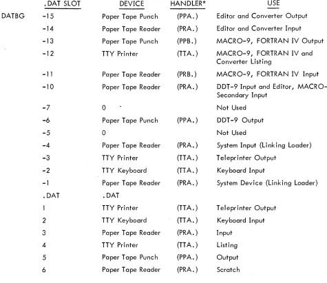
2.3 DEVICE ASSIGNMENTS
The device assignment table used by the I/O Monitor is fixed both in length and in the
as-signments it conta ins. I t is composed of two sections: the .upper section is for use by system programs;
the lower section is referenced by all user programs.
The upper portion of the . DA T conto ins 13 slots, referenced as -1 through -15
8, The lower section has 8 slots numbered 1 through 10
8, The fixed assignments for the device assignment table are shown in Figure 2-4.
*Bits 0-2 of LOC + 2 must be set to zero prior to the execution of the CAL at LOC. On return, bits 0-2 of LOC
+
2 wi II contain a code indicating the type of device associated with. DAT slot a.0= Non-file-oriented devices
1
=
DECtapeThese assignments will be changed by Digital as additional peripherals are added to a PDP-9 system. For example, .DAT slot 3 might be associated with a card reader, while .DAT slot 4 could be assigned to a line printer.
2.4
PROGRAMMING WITH USER PROGRAM COMMANDSIn the FORTRAN IV system, I/O commands, READ (u), WRITE (u), READ (u, f), WRITE (u, f), automatically generate cal~s to the FORTRAN IV Object-Time System, which performs data level I/O via .DATslotu. In MACRO-9 programs, the user program commands (discussed above) must be used expl ic itly.
• DAT SLOT DEVICE HANDLER* USE
. DATBG
-15
Paper Tape Punch (PPA. ) Editor and Converter Output-14
Paper Tape Reader (PRA. ) Editor and Converter Input-13
Paper Tape Punch (PPB. ) MACR 0-9, FORTRAN IV Output-12
TTY Printer (TTA. ) MACRO-9, FORTRAN IV andConverter Listi ng
-11
Paper Tape Reader (PRB. ) MACRO-9, FORTRAN IV Input-10
Paper Tape Reader (PRA. ) DDT -9 Input and Editor, MACRO-9 Secondary Input-7
0 Not Used-6
Paper Tape Punch (PPA.) DDT -9 Output-5
0
Not Used-4
Paper Tape Reader (PRA. ) System Input (Li nk i ng Loader)-3
TTY Printer (TTA. ) Teleprinter Output-2
TTY Keyboard (TT A.) Keyboard Input-1
Paper Tape Reader (PRA. ) System Device (Linking Loader).DAT .DAT
TTY Printer (TTA. ) Teleprinter Output
2
TTY Keyboard (TT A.) Keyboard Input3
Paper Tape Reader (PRA. ) Input4
TTY Printer (TTA. ) Listi ng5
Paper Tape Punch (PPA. ) Output [image:34.612.98.573.260.671.2]6
Paper Tape Reader (PRA. ) ScratchFigure