DIGITAL Facility, Parker Street, Maynard, Massachusetts
CORPORATE PROFILE
Copyright© 1981 Digital Equipment Corporation. All Rights Reserved.
Digital Equipment Corporation makes no representation that the in-terconnection of its products in the manner described herein will not infringe on existing or future patent rights, nor do the descrip-tions contained herein imply the granting of license to make, use, or sell equipment constructed in accordance with this description. The information in this document is subject to change without notice and should not be construed as a commitment by Digital Equipment Corporation. Digital Equipment Corporation assumes no responsi-bility for any errors that may appear in this manual.
DEC, DECnet, DECsystem-10, DECSYSTEM-20, DECtape DECUS, DECwriter, DIBOL, Digital logo, lAS, MASSBUS, OMNIBUS
PDP, PDT, RSTS, RSX, SBI, UNIBUS, VAX, VMS, VT are trademarks of
Digital Equipment Corporation
This handbook was designed, produced, and typeset by DIGITAL's New Products Marketing Group
using an in-house text-processing system.
CHAPTER 1 INTRODUCTION ... 1
CHAPTER 2 DISK DRIVES RX211 ... 4
RL01/02 ... 14
RK07 ... 24
RM02/03 ... 34
RM60 ... 46
RP06 ... 56
RM05 ... 70
RP07 ... 62
DISK DRIVE COMPARISON CHART ... 91
CHAPTER 3 MAGNETIC TAPES TU56 ... 92
TS11 ... 106
TE16 ... 120
TU77 ... 134
TU76 ... 146
MAGNETIC TAPE COMPARISON CHART ... 159
CHAPTER 4 LlNEPRINTERS LXY11/21 ... 160
LP11 SERIES ... 172
LINEPRINTER COMPARISON CHART ... 169
CHAPTER 5 CARD READERS CR11 SERIES ... 190
CMS11-K/CME11-K ... 202
CARD READER COMPARISON CHART ... 212
CHAPTER 6 SENSOR
I/O
DEVICES AA11-K ... 214AD11-K ... 220
AM11-K ... 226
DR11-C ... 233
DR11-K ... 236
1811 ... 251
KWll-K ... 256
LPAll-K ... 262
CHAPTER 7 REGISTER DIAGRAMS AND BIT DEFINITIONS DISK REGISTERS ... 275
MAGNETIC TAPE REGISTERS ... 368
LINEPRINTER REGISTERS ... 439
CARD READER REGiSTERS ... 442
SENSOR I/O DEVICE REGISTERS ... 446
APPENDIX A STANDARD AND COMPRESSED HOLLERITH CODE CHART . ... A 1 APPENDIX B EXAMPLES OF LXY11/LXY21 PRINT COPY AND GRAPHICS . ... 81
INTRODUCTION
DIGITAL's family of computer peripherals is continually growing to provide you with the hardware that most precisely meets your needs. Cost effectiveness, capacity, ease of use, reliability, maintainability, and serviceability are constantly being upgraded.
The two most recent additions to DIGITAL's family of computer peri-pherals supported by VAX systems are the RP07 disk drive, utilizing Winchester fixed-media technology, and the TU78 magnetic tape transport, using Group Coded Recording (GCR) technology. These new peripherals combine state-of-the-art microprocessor control, large capacity, high speed, and self-test diagnostics. Other new disk drives include the RM80 and RM05. The RM80 disk drive, which also utilizes Winchester fixed-media technology and advanced microproc-essor control, is supported on VAX systems. The RM05 is supported on both VAX-11 /780 and PDP-11/70 systems. The latest lineprinters include the high-speed LP11-E band lineprinter with 64- and 96-char-acter sets and the high-speed LXY21 printer/plotter, both supported by UNIBUS PDP-11 systems and VAX systems.
With the purchase of one of DIGITAL's peripherals, you will receive detailed user and maintenance documentation. This information may be supplemented by the excellent tutorial guides to DIGITAL's soft-ware languages and operating systems and by other volumes in the Handbook series. DIGITAL's Educational Services group offers a wide range of hardware and software courses specifically designed to ad-dress customers' needs.
In addition, DIGITAL's Computer Special Systems (CSS) group pro-vides customers with design service and products to complement the corporation's high volume offerings. CSS products address the cus-tomers' needs in the process I/O, graphics, networks products, and special terminals marketplaces.
INTRODUCTION
This book is divided into chapters by device type. Each chapter is further subdivided into sections by device. Each section contains the following:
• an introduction • a list of features • a general description • packaging information
• data formats and data organization information (where applicable) • operation description
• interrupt information
• reliability/maintainability features
• controls and indicators (where applicable) • specifications
At the end of the disk, magnetic tape, lineprinter, and card reader chapters is a comparison chart of the peripherals in that chapter. This allows easy comparison among like devices to ensure the best selec-tion for your needs. The specificaselec-tion informaselec-tion is subject to change without notice, and should be considered as a guide only. For specific site preparation information, please consult your local DIGITAL sales office.
Chapter 7 contains the register diagrams and bit definitions for all the peripherals described in this book. The appendices contain addition-al, relevant information including an ASCII code chart, a standard and compressed Hollerith code chart, and UNIBUS addresses and vector assignments for DIGITAL'S peripherals.
In addition to the Peripherals Handbook, DIGITAL's series of handbooks includes the Terminals and Communications Handbook, the PDP-11 Processor and Software Handbooks, the Microcomputer Processor, Microcomputer Interfaces, and Microcomputers and Memories Handbooks, and the VAX Hardware, Software, and Archi-tecture Handbooks.
-2-RX211
CHAPTER 2
DISK DRIVES
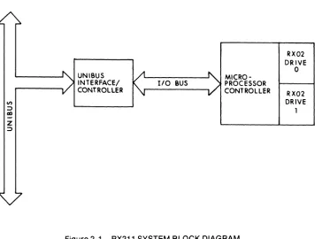
The RX211 is a dual-drive, double density, floppy disk subsystem connected to the UNIBUS via an interface/controller. The RX211-BA(BD) subsystems are supported by UNIBUS PDP-11 systems.
VAX-11/750 systems also support the RX211-BA(BD) subsytems, but only
as a data file resident device for transport of data to and from other DIGITAL systems. The low cost of the RX211 subsystem makes it ideal for archive storage, diagnostic loading, or software updates.
FEATURES
• Double density recording provides greater data storage capacity • Program-selectable single density mode provides compatibility with
other floppy disk subsystems
• 0.5 MB of formatted data storage capacity per diskette (1 MB total per RX211 subsystem)
• Direct Memory Access (DMA) data transfers • Microprocessor controller
• Compact, removable diskettes
DESCRIPTION
The RX211-BA(BB) floppy disk subsystems consist of two RX02 floppy disk drives, a microprocessor controller, an interface/controller, and a 15 ft (4.6 m) I/O cable. Up to two RX211 subsystems (a total of four RX02 floppy disk drives) are supported by UNIBUS PDP-11 systems and VAX-11 /750 systems.
The RX211 floppy disk subsystems use industry standard diskettes. They are thin, flexible disks similar in size to a 45-rpm phonograph record. These diskettes are recorded on one side only. In double density mode, each diskette can store 0.5 MB of data. The program-selectable single density mode provides compatibility with other flop-py disk subsystems, such as the RX11.
RECORDING METHODS
I en I
<II ;:)
cD
z
;:)
UNIBUS INTERFACE/ CONTROLLER
[image:12.568.118.482.58.328.2]110 BUS PROCESSOR MICRO-CONTROLLER
Figure 2-1 RX211 SYSTEM BLOCK DIAGRAM
RX02 DRIVE
o
RX02 DRIVE 1
S2
~
o
:Xl
compatability with other floppy disk subsystems. Data is written on the diskette by magnetizing small sections (bit cells) of the oxide on the diskette in different directions, i.e. either positively or negatively. A change in the direction of magnetization (flux tranSition) in the clock i1flla or data area of a bit cell indicates whether the bit represented is a
lor a O.
DATA ORGANIZATION
The RX211 has one read/write head that is used to both read and write data. The diskette surface is divided into 77 tracks. Each track is divided into 26 sectors with a data storage capacity of 2048 bits (256 bytes). Each sector is divided into a header field and a data field. The header field consists of a header preamble, a 56-bit header that con-tains the track and sector addresses, and a 16-bit header CRC (Cyclic Redundancy Check). The data field consists of a data preamble, an 8-bit code specifying the recording density, 2048 8-bits (256 bytes) of data, and a 16-bit data CRC. The header field is permanently recorded and can not be written by the RX211.
OPERATION
The RX211 controller has two registers: the Command and Status register and the Data Buffer register. The Data Buffer register is used to perform five different functions. When used to specify the diskette track, it is called the Track Address register. When used to specify the diskette sector, it is called the Sector Address register. When used to specify the number of data words to be transferred, i.e. the word count, it is called the Word Count register. When used to specify the starting memory address of the data to be transferred to or from memory, it is called the Bus Address register. When used to provide status information and specify errors, it is called the Error and Status register. When an error is detected, a READ ERROR CODE command will cause the controller to write four extended status words into mem-ory. These extended status words contain detailed error and status information. (Refer to the register section at the back of this book for register and extended status word diagrams and bit definitions.)
DISK DRIVES
The microprocessor controller positions the RX211 head to the track specified and reads each sector address from the sector header as it passes by on the rotating diskette until the specified sector is reached. The 2048 bits of data are then read and stored in the microprocessor's internal data buffer. When the data buffer is full, the microprocessor generates an interrupt to alert the processor that the data has been read off the diskette.
To transfer the data read off the diskette into memory, the processor loads the command and status register with an EMPTY BUFFER com-mand. The microprocessor controller responds with a request for the number of data words to be transferred by setting TRANSFER RE-QUEST <07> in the command and status register. The processor then loads the word count into the data buffer register. The microproc-essor next requests the starting memory address where the data read off the diskette is to be stored in memory by again setting TRANSFER REQUEST <07>, and the processor responds by loading the bus address into the data buffer register.
The microprocessor controller assembles the 2048 bits of data in its internal data buffer into 16-bit words and generates a parity bit for each word. Each 16-bit word plus parity is written into the memory location specified. This process continues until the proper word count is reached. Finally, the microprocessor generates an interrupt to alert the processor that the data read off the diskette has been stored in memory.
To begin a WRITE operation, the processor loads the command and status register with a FILL BUFFER command. The microprocessor controller responds with a request for the number of data words to be transferred by setting TRANSFER REQUEST <07>. The processor then loads the word count into the data buffer register. The microproc-essor next requests the starting memory address of the data to be written onto the diskette by again setting TRANSFER REQUEST <07>, and the processor responds by loading the bus address into the data buffer register. The WRITE operation has now been initiated.
The microprocessor controller transfers the 16-bit words of data from memory, one by one, into its internal data buffer. This process contin-ues until the proper word count is reached. The microprocessor gen-erates an interrupt to alert the processor that the internal data buffer has been loaded.
sector address into the data buffer register. The microprocessor next requests the track address by again setting TRANSFER REQUEST <07>, and the processor responds by loading the track address into the data buffer register.
The microprocessor controller positions the RX211 head to the track specified and reads each sector address from the sector header as it passes by on the rotating diskette until the specified sector is reached. The microprocessor then serially writes the 2048 bits of data into the sector and generates an interrupt to alert the processor that the data has been written onto the diskette.
DATA INTEGRITY
Several error checking and correction features of the RX211 ensure that the data is correct.
The RX211 locates the specified track and then reads the header information to verify that it is the specified track. The header CRC is used to ensure that the header field has been read correctly. The header bits are used to generate a second CRC, which is then com-pared to the CRC read from the end of the header field on the diskette. If there is a discrepancy between the two CRCs, the microprocessor controller alerts the processor via an error code in the extended status word 1.
The data CRC is used to ensure that the data field has been read correctly. The data bits are used to generate a second CRC, which is then compared to the CRC read from the end of the data field on the diskette. If there is a discrepancy between the two CRCs, the microprocessor controller alerts the processor by setting a bit in the error and status register.
INTERRUPTS
The RX211 floppy disk subsystem microprocessor controller uses a vectored interrupt to cause the program to branch to an interrupt service routine. An interrupt can occur only if the INTERRUPT EN-ABLE bit in the command and status register is set. Once the INTER-RUPT ENABLE bit is set, an interrupt request is generated whenever either the ERROR or DONE bit in the command and status register is also set.
pro-DISK DRIVES
gram can branch to an interrupt service routine.
The interrupt priority level is 5 and the interrupt vector address is 264. Note that the priority level can be changed with a priority plug and the vector address can be changed by switches in the interrupt control logic. However, any DIGITAL programs or other software referring to the priority level or interrupt vector address must also be changed if the priority plug or the vector address is changed.
RELIABILITY/MAINTAINABILITY
Reliability means long life expectancy and uninterrupted processing of the floppy disk subsystem. Special design features of the RX211 subsystems provide these qualities of high reliability as well as ease of maintenance .
• Modular construction of the RX211 enables parts to be quickly re-moved and replaced during routine servicing and maintenance . • Long head and diskette life due to minimal contact since the head
only touches the diskette during an operation.
SPECIFICATIONS
MECHANICAL Cabinet
Controller mounting code
Height
Width
Depth
Weight
PERFORMANCE
Cabinet-mountable
One quad slot
10.5 in (26.7 cm)
19 in (48.3 cm)
17 in (43.2 cm)
60 Ibs (27 kg)
Drives per controller 2
Formatted capacity per diskette 0.5 MB
Peak transfer speed 61 KB/s
Average access time* 262 ms
* Average access time is defined as the sum of the average seek time, the settling time, and the average latency (rotational) time.
-10-Average seek time
Average latency (rotational) time
Settling time
Track-to-track seek
Rotational speed
Data surfaces per diskette
Tracks per diskette
Sectors per track
Bytes per sector
Tracks per inch
Bits per inch
ELECTRICAL Operating current
Interface (controller) current
Power Consumption Heat dissipation Operating voltage Phase Line frequency Receptacles
Line cord length
ENVIRONMENTAL Operating temperature Storagl3 temperature 154 ms 83ms 25 ms 6ms 360 rpm 1 77 26
256 (8-bit format)
48
3200
4Aat120Vac 2 A at 240 Vac
1.5 A at +5 Vdc
500 Watts
1700 Btus/hr
120Vac ± 10% 240 Vac
±
10%1-Phase
60 Hz ± 0.5 Hz 50 Hz ± 0.5 Hz
NEMA #5-15R (120 Vac), NEMA #6-15R (240 Vac)
9ft
59°F-90°F (15°C-32°C)
DISK DRIVES
Operating relative humidity 20%-80%
(non-condensing)
Storage relative humidity 5%-98%
(non-condensing)
Maximum wet bulb temperature 78°F (26°C)
Maximum operating altitude 8,000 ft (2440 m) above sea level
RL01/02
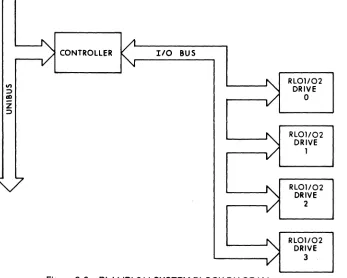
The RL01/02 is a random-access, cartridge disk storage system which connects to the UNIBUS via the controller. The RL 11-AK and RL211-AK subsystems are supported by UNIBUS PDP-11 systems. VAX-11/750 systems also support the RL211-AK subsytems, but only as a data file resident device for transport of data to and from other DIGITAL systems. The RL01/02 was designed to operate at medium speeds in moderate usage environments in a wide range of commer-cial, engineering, laboratory, educational, and even some industrial and military applications.
FEATURES
• Formatted capacity of 10.4 MB (RL02) and 5.2 MB (RL01) • Removable disk cartridge provides unlimited off-line storage • Overlapped seeks optimize seek time and provide increased system
throughput on multidrive systems
• Direct Memory Access (DMA) data transfers
• Expandable up to a total of 4 disk drives per subsystem
DESCRIPTION
The RL 11-AK subsystem consists of a toploading, RL01 cartridge disk drive, a controller, an I/O cable, and a disk cartridge. Up to three more add-on RL01-AK cartridge disk drives may be added to this subsys-tem. Each processor will support a maximum of two controllers. The RL211-AK subsystem consists of a toploading, RL02 cartridge disk drive, a controller, an I/O cable, and a disk cartridge. Up to three more add-on RL02-AK cartridge disk drives may be added to this subsys-tem. Each processor will support a maximum of two controllers.
RECORDING METHOD
The RL01/02 utilizes Modified Frequency Modulation (MFM) to read and write data. Data is written on the disk by magnetizing small sec-tions (bit cells) of the oxide on the disk in different direcsec-tions, i.e. either positively or negatively. A change in the direction of magnetization (flux transition) in the clock area or the data area of a bit cell indicates whether the bit represented is a 1 or a O.
DATA ORGANIZATION
I
....
0) I
I/) : )
ell
Z
: )
[image:22.568.125.472.47.325.2]CONTROLLER I/O BUS
Figure 2-2 RL 11/RL211 SYSTEM BLOCK DIAGRAM
RL01/02 DRIVE
o
RL01/02
DRIVE 1
RL01/02 DRIVE
2
RL01/02
DRIVE 3
o
~
o
~bytes). Each sector is divided into a servo field, a header field, and a data field. The header field consists of a 16-bit header that contains the cylinder, track, and sector addresses and a 16-bit header CRC (Cyclic Redundancy Check). The data field consists of 2048 bits (256 byles) of data and a 16-bit data CRC. The sector field and the header field are permanently recorded and can not be rewritten by the disk drive.
OPERATION
The RL1l1RL211 subsystems have the following four registers: the Control and Status Register, the Bus Address Register, the Disk Address Register, and the Multipurpose Register. (Refer to the regis-ler section at the back of this book for register diagrams and bit definitions.)
Before a READ or a WRITE operation can begin, the processor must issue a SEEK command unless the heads are already positioned at the desired cylinder. To initiate a SEEK command, the processor loads the disk address register with the number of cylinders the heads are to be moved, the direction they are to be moved (toward or away from the spindle), and the head to be used (track 0 or 1). The control and status register is then loaded to select the drive number (0-3) and specify the SEEK command. The drive moves the heads the number of cylinders specified and generates an interrupt when the SEEK opera-tion has been completed.
Once the heads are positioned at the desired cylinder, the processor loads the multipurpose, bus address, and disk address registers re-spectively. The multipurpose register specifies the number of words to be transferred between the disk and memory. The bus address regis-ter specifies the starting memory address of the location for the data to be read from or written onto the disk. The disk address register specifies the sector of the disk to be read or written.
After the multipurpose, bus address, and disk address registers have been loaded, the control and status register is loaded to specify the drive number (0-3) and whether this is to be a READ or WRITE operation. The READ or WRITE command is then executed. The spec-ified head then reads the sector header fields to locate the specspec-ified sector on the rotating disk.
DISK DRIVES
end of the current track, whichever comes first. When the READ oper-ation has been completed, an interrupt is generated to alert the proc-essor that the data has been read off the disk and is stored in the specified memory location.
During a WRITE operation, the controller reads each 16-bit parallel word from the specified memory location and generates a parity bit for each 16-bit word. The controller then transfers each 16-bit word plus parity to the drive. The drive serially writes the bits onto the disk. This process continues until the specified number of words is reached or until the end of the current track, whichever comes first. When the WRITE operation has been completed, an interrupt is generated to alert the processor that the data has been written onto the disk.
DATA INTEGRITY
Several error checking and correction features of the RL01/02 ensure that the data is correct.
During a data transfer operation, the RL01/02 reads the sector header field to verify that it has reached the specified cylinder, traCk, and sector. The header CRC is used to ensure that the header field has been read correctly. The header bits are used to generate a second CRC, which is then compared to the CRC read from the end of the header field on the disk. If there is a discrepancy between the two CRCs, the controller alerts the processor by setting a bit in the control and status register.
The data CRC is used to ensure that the data field has been read correctly. The data bits are used to generate a second CRC, which is then compared to the CRC read from the end of the data field on the disk. If there is a discrepancy between the two CRCs, the controller alerts the processor by setting a bit in the control and status register. If a sector contains an error, the processor issues a RETRY command.
To ensure that data is written correctly, a WRITE CHECK command may be issued by the software. This causes the RL01/02 to read the data just written and the RL01/02 controller to compare it to the data stored in memory.
INTERRUPTS
When the COMPOSITE ERROR bit is set in addition to the DRIVE READY bit, it indicates that some error or unusual condition exists and an interrupt is generated to cause the program to branch to an error handling routine. When the CONTROLLER READY bit is set, the con-troller has successfully completed the operation and is ready to accept a command. An interrupt request is made so that the program can branch to an interrupt service routine.
The interrupt priority level is 5 and the interrupt vector address is 160. Note that the priority level can be changed with a priority plug and the vector address can be changed by jumpers in the interrupt control logic. However, any DIGITAL programs or other software referring to the priority level or interrupt vector address must also be changed if the priority plug or the vector address is changed.
RELIABILITY /MAINT AINABILITY
Reliability means long life expectancy and uninterrupted processing of the disk system. Special design features of the RL01/02 disk systems provide these qualities of high reliability as well as ease of mainte-nance .
• Modular construction of the RL01/02 enables parts to be quickly removed and replaced during routine servicing and maintenance. • Easy access from the top of the drive to the subassemblies and
heads .
• Track-following embedded servo system minimizes maintenance by eliminating drive head alignment.
WRITE PROT
DISK DRIVES
PANEL CONTROLS AND INDICATORS
The front panel controls allow the operator to control the disk drive manually. The indicator lights provide drive status information. • LOAD switch (alternate-action pushbutton/white light indicator on
front panel)
Depressing this switch causes the indicator light to go out and the drive to accelerate the disk up to speed. Once the disk is up to speed, the READY indicator will light. Depressing the switch again causes the drive to stop the disk and the LOAD indicator to light. • DRIVE NUMBER receptacle/READY indicator (unlabeled
recepta-cle/white light indicator on front panel)
Each drive comes with four numbered (0-3) plugs. The drive num-ber is set by inserting one of the numnum-bered plugs into the recepta-cle. If no plug is in the receptacle, the drive cannot be selected by the processor. Note that drive number units cannot be duplicated. When lit, the disk is up to speed and the drive is ready to execute a command.
• FAULT indicator (white light indicator on front panel)
When lit, the drive has detected a hardware fault such as write current failure or loss of system clock.
• WRITE PROTECT switch (alternate-action pushbutton/white light in-dicator on front panel)
Depressing this switch causes the indicator to light and prevents the processor from writing on the disk cartridge. Depressing this switch again causes the indicator light to go out and enables WRITE operations.
SPECIFICATIONS
MECHANICAL Cabinet
Controller mounting code
Height
Width
Depth
Weight
Cabinet-mountable
One hex slot
10.5 in (26.7 cm)
19 in (48.3 cm)
25 in (63.5 cm)
PERFORMANCE Drives per controller
Formatted capacity per disk cartridge
RL01
RL02
Peak transfer speed
Average access time·
Average seek time
Average latency (rotational) time
Track-to-track seek
Rotational Speed
Surfaces per disk cartridge
Tracks per surface
RL01
RL02
Sectors per track
Bytes per sector
Tracks per inch
Bits per inch
ELECTRICAL
Starting (surge) current
Surge duration
Operating current
4
5.2MB
10.4 MB
512 KB/s
67.5 ms
55ms
12.5 ms
15ms
2400 rpm
2
256
512
40
256
250
3725
5 A at 120 Vac 2.5 A at 240 Vac
10
s
1.5 A at 120 Vac 0.8 A at 240 Vac
DISK DRIVES
Controller (Interface) current
Power consumption
Heat dissipation
Operating voltage
Phase
line frequency
Receptacles
line cord length
ENVIRONMENTAL
5 A at 5 Vdc, 0.5 A at +15 Vdc, 0.5 A at -15 Vdc
150 Watts
600 Btus/hr
120Vac ± 10% 240 Vac ± 10%
1-Phase
60 Hz ± 3 Hz 50 Hz ± 2.5 Hz
NEMA #5-15R (120 Vac), NEMA #6-15R (240 Vac)
10ft(3m)
Operating temperature 50°F-104°F (10°C-40°C)
Storage temperature -40°F-151°F (-40°C-66°C)
Operating relative humidity 10%-90% (non-condensing)
Storage relative humidity 10%-95% (non-condensing)
Maximum wet bulb temperature 82°F (28°C)
-RK07
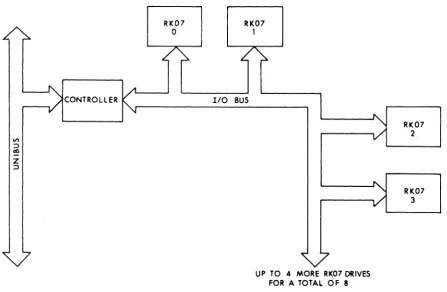
The RK07 is a freestanding, random-access, disk storage system which connects to the UNIBUS via the controller. The RK711 subsys-tems are supported by UNIBUS PDP-11 syssubsys-tems and VAX-111780 systems. The RK07 was designed to operate at medium speeds in moderate usage environments in a variety of commercial and scientif-ic applscientif-ications.
FEATURES
• Formatted capacity of 28 M B
• Removable disk cartridge provides unlimited off-line storage • Overlapped seeks optimize seek time and provide increased system
throughput on multidrive systems • Static dual-access capability
• Direct Memory Access (DMA) data transfers
• Expandable up to a total of 8 disk drives per subsystem
DESCRIPTION
The RK711-EA(ED) and RK711-PA(PD) disk storage subsystems con-sist of a single-access, freestanding RK07 disk drive, a controller, an I/O cable, and a disk cartridge. Up to seven more add-on RK07 drives (single- or dual-access) may be added to these subsystems. The RK711-EA(ED) subsystems and the RK07-EA(ED) add-on drives are compatible with UNIBUS PDP-11 and VAX-111780 systems configured in H960 and H9600 series cabinets. The RK711-PA(PD) subsytems and the RK07-PA(PD) add-on drives are compatible with UNIBUS PDP-11 systems configured in H9640 series cabinets. The RK07-PA(PD) add-on drive may also be added to VAX-111750 systems con-fiugred with an RK711 subsystem.
I
I\)
en I
I/) :::>
011
Z
:::>
CONTROLLER
RK07
o
RK07 1110 BUS
[image:32.569.71.518.29.320.2]UP TO 4 MORE RK07 DRIVES FOR A TOTAL OF 8
Figure 2-4 RK711 SYSTEM BLOCK DIAGRAM
RK07 2
RK07 3
~
RECORDING METHOD
The RKO? utilizes Modified Frequency Modulation (MFM) to read and write data. Data is written on the disk by magnetizing small sections (bit cells) of the oxide on the disk in different directions, i.e. either positively or negatively. A change in the direction of magnetization (flux transition) clock area or the data area of a bit cell indicates wheth-er the bit represented is a 1 or a O.
DATA ORGANIZATION
The RKO? disk cartridge consists of 2 disk platters, each recorded on both sides, enclosed in a protective cover. Each disk cartridge con-tains a total of 4 surfaces: 3 data surfaces for recording and 1 servo surface permanently recorded with information used to position the read/write heads at the specified cylinder. The RKO? has 4 heads-3 are read/write heads which correspond to the 3 data surfaces and the additional head is the servo read head, which corresponds to the servo surface. The disk cartridge is divided into 815 cylinders. Each cylinder is divided into 3 tracks, corresponding to the 3 data surfaces. Each track is divided into 22 sectors with a data storage capacity of 4096 bits (512 bytes). Each sector is divided into a preamble, a header field, and a data field. The header field consists of a 32-bit header that contains the cylinder, track, and sector addresses and a 16-bit header check word. The data field consists of 4096 bits (512 bytes) of data and a 32-bit data ECC (Error Correcting Code). The preamble and the header field can only be written by the utility program that formats these disk cartridges.
OPERATION
The RK?11 subsystems have 15 registers. (Refer to the register sec-tion at the back of this book for register diagrams and bit definisec-tions).
Before a READ or a WRITE operation can begin, the processor loads the bus address, word count, control and status 2, desired cylinder, disk address, and control and status 1 registers respectively.
The bus address register specifies the starting memory address of the location for the data to be read from or written onto the disk. The word count register specifies the number of words to be transferred between the disk and memory. The control and status 2 register se-lects which of the disk drives (up to 8 per controller) is to perform the operation. The desired cylinder register and the disk flddress register specify the sector of the disk to be read or written.
DISK DRIVES
processor. The command is then executed. If the heads are not cur-rently positioned at the specified cylinder, the drive will do an implied SEEK, which moves the heads to the correct cylinder. The read/write data heads then begin reading the headers on the specified track to locate the specified sector.
During a READ operation, data bits are read from the disk serially. The controller assembles the bits into 16-bit parallel words and generates a parity bit for each bit word. The controller then transfers each 16-bit word plus parity to the specified memory location. This process continues until the proper word count is reached. When the READ operation has been completed, an interrupt is generated to alert the processor that the data has been read off the disk and is stored in the specified memory location.
During a WRITE operation, the controller reads each 16-bit parallel word from the specified memory location and generates a parity bit for each 16-bit word. The controller then transfers each 16-bit word plus parity to the drive. The drive serially writes the bits onto the disk. This process continues until the proper word count is reached. When the WRITE operation has been completed, an interrupt is generated to alert the processor that the data has been written onto the disk.
DATA INTEGRITY
Several error checking and correction features of the RK07 ensure that the data is correct.
The RK07 uses the servo disk surface to position the read/write heads at the specified cylinder. The sector header field is read to verify that it is the specified cylinder, track, and sector. The header check word is used to ensure that the header field has been read correctly. The header bits are used to generate a second header check word, which is then compared to the word read from the end of the header field on the disk. If there is a discrepancy between the two header check words, the controller alerts the processor by setting a bit in the error register.
To ensure that data is written correctly, a WRITE CHECK command may be issued by the software. This causes the RK07 to read the data just written and the RK07 controller to compare it to the data stored in memory.
The ECC (Error Correction Code) logic is used to ensure that the data field has been read correctly. The data bits are used to generate a second ECC, which is then compared to the ECC read from the end of the data field on the disk. If there is a discrepancy between the two ECCs, the processor uses them to determine which bits are in error
-28-and to reconstruct the correct data. One error of up to 11 incorrect bits In a row can be reconstructed in a sector. The controller reports the position of the error to the processor and sends the processor an error burst pattern and an error correction pattern to allow the software to correct the error in memory. If a sector containing more than one error is reported to the procesor by the controller as an incorrectable error, the processor may invoke a suitable error recovery procedure consist-ing of OFFSET positionconsist-ing, RECALIBRATION, and REREAD opera-tions.
INTERRUPTS
The RKO? disk system controller uses a vectored interrupt to cause the program to branch to an interrupt service routine. An interrupt can occur only if the INTERRUPT ENABLE bit in the control and status 1 register is set. Once the INTERRUPT ENABLE bit is set, an interrupt request is generated whenever either the COMBINED ERROR, DRIVE INTERRUPT, or CONTROLLER READY bit in the control and status 1 register is also set.
When the COMBINED ERROR or DRIVE INTERRUPT bits are set, they indicate that some error or unusual condition exists and an interrupt is generated to cause the program to branch to an error handling rou-tine. When the READY bit is set, the controller has successfully com-pleted the operation and is ready to accept a command. An interrupt request is made so that the program can branch to an interrupt service routine.
The interrupt priority level is 5 and the interrupt vector address is 210. Note that the priority level can be changed with a priority plug and the vector address can be changed by switches in the interrupt control logic. However, any DIGITAL programs or other software referring to the priority level or interrupt vector address must also be changed if the priority plug or the vector address is changed.
RELIABILITY/MAINTAINABILITY
Reliability means long life expectancy and uninterrupted processing of the disk system. Special design features of the RKO? disk systems provide these qualities of high reliability as well as ease of maintenance.
• Modular construction and easy access to the subassemblies and heads of the RKO? enables parts to be quickly removed and re-placed during routine servicing and maintenance.
• Off-line tester allows the RK07 to be serviced independent of the host processor.
DISK DRIVES
~
I I I
r::l
I
WRITEI
~A
InIB
~
~
L:J
PROTL.J
~
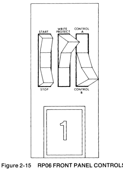
Figure 2-5 RK07 FRONT PANEL CONTROLS AND INDICATORS
PANEL CONTROLS AND INDICATORS
The front panel controls allow the operator to control the disk drive manually. The indicator lights provide drive status information. • RUN/STOP switch (alternate-action pushbutton/yellow light
indica-tor on front panel)
Depressing this switch causes the indicator to light and the drive to accelerate the disk cartridge up to speed. Once the disk cartridge is up to speed, the READY indicator will light. Depressing the switch again causes the drive to stop the disk cartridge and the START indicator light to go out.
• DRIVE NUMBER receptacle/READY indicator (unlabeled recepta-cle/white light indicator on front panel)
Each drive comes with eight numbered (0-7) plugs. The drive number is set by inserting one of the numbered plugs into the re-ceptacle. If no plug is in the receptacle, the drive cannot be selected by the processor. Note that drive number units cannot be duplicat-ed.
When this READY indicator is lit, the disk cartridge is up to speed and the drive is ready to execute a command.
• FAULT indicator (red light indicator on front panel)
When lit, the drive has detected a hardware fault such as write current failure or a dc power supply failure.
• WRITE PROTECT switch (alternate-action pushbutton/yellow light indicator on front panel)
Depressing this switch causes the indicator to light and prevents the processor from writing on the disk cartridge. Depressing this switch again causes the indicator light to go out and enables WRITE opera-tions.
• A and B switches (alternate-action push buttons/white light indica-tors on front panel)
Depressing switch A enables port A. Depressing switch B enables port B. When both switches are depressed both ports are enabled. The A indicator lights when the drive is being accessed by port A and the B indicator lights when the drive is being accessed by port
SPECIFICATIONS MECHANICAL Cabinet
Controller mounting code
Height RK07-EA(ED, RK07-FA(FD) RK07-PA(PD) Width RK07-EA(ED), RK07-FA(FD) RK07-PA(PD) Depth RK07-EA(ED), RK07-FA(FD) RK07-PA(PD) Weight RK07-EA(ED), RK07-FA(FD) RK07-PA(PD) PERFORMANCE Drives per controller
Formatted capacity per disk cartridge
Peak transfer speed
Average access time·
Average seek time
Average latency (rotational) time
Track-to-track seek
Rotational Speed
Surfaces per disk cartridge
Tracks per surface
Freestanding
2Sus
39 in (99cm)
41.75in(106cm)
21.7 in (55.2 cm)
21.25 in (54.1 cm)
30 in (76.2 cm)
30 in (76.2 cm)
3261bs (148 kg)
3391bs (153.9 kg)
8 28MB 538 KB/s 49ms 36.5 ms 12.5 ms 6.5ms 2400 rpm
3 data, 1 servo
815
Sectors per track
Bytes per sector
Tracks per inch
Bits per inch
ELECTRICAL
Operating current
Controller (Interface) current
Power Consumption
Heat dissipation
Operating voltage
Phase
Line frequency
RecElPtacles
Line cord length
ENVIRONMENTAL
DISK DRIVES
22 (16-bit format)
512
384
4040
4 A at 120 Vac 2 A at 120 Vac
12Aat5Vdc, .18 A at +15 Vdc, .40 A at -15 Vdc
500 Watts maximum (60 Hz) 550 Watts maximum (50 Hz)
1700 Btus/hr maximum (60 Hz) 1900 Btus/hr maximum (50 Hz)
120 Vac ± 10% 240 Vac ± 10%
1-Phase
60 Hz ± 3 Hz 50 Hz ± 3 Hz
NEMA #5-15R (120 Vac), NEMA #6-15R (240 Vac)
9 ft (2.7 m)
Operating temperature 50°F-104°F (10°C-40°C)
Storage temperature -40°F-151°F (-40°C-66°C)
Operating relative humidity 10%-90% (non-condensing)
Storage relative humidity 10%-95%
(non-condensing)
Maximum wet bulb temperature 82°F (28°C)
RM02/03
-RM02/03
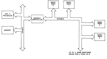
The RM02/03 is a freestanding, random-access, disk storage system which connects to the processor via the MASSBUS controll-er/adapter. The RJM02 subsystems are supported by UNIBUS PDP-11 systems except the PDP-PDP-11170, the RWM03 subsystems are sup-ported by PDP-11170 systems, the REM03 subsystems are supsup-ported by VAX-11 /780 systems, and the RGM03 subsystems are supported by VAX-11 /750 systems. The RM02/03 was designed to operate at high speeds in high usage environments in a variety of applications.
FEATURES
• Formatted capacity of 67 MB
• Removable disk pack provides unlimited off-line storage
• Overlapped seeks optimize seek time and provide increased system throughput on multidrive systems
• Static dual-access capability
• Direct Memory Access (DMA) data transfers
• Expandable up to a total of 8 disk drives per subsystem DESCRIPTION
The RJM02-AA(AD) disk storage subsystems consist of a single-ac-cess, freestanding RM02 disk drive, a MASS BUS controller, a MASS-BUS cable, and a disk pack. Up to seven more add-on RM02 disk drives (single- or dual-access) may be added to these subsystems. The RWM03-AA(AD), REM03-AA(AD), and RGM03-AA(AD) disk storage subsystems consist of a single-access, freestanding RM03 disk drive, a MASSBUS controller/adapter, a MASSBUS cable, and a disk pack. Up to seven more add-on RM03 disk drives (single- or dual-access) may be added to these subsystems.
I
I CJ.) 0) I
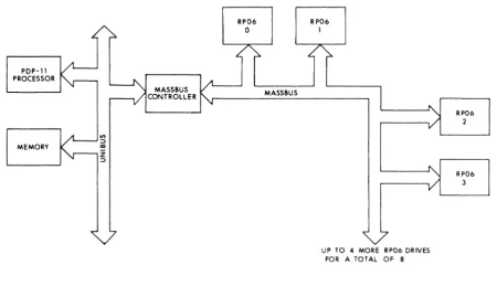
PDP-11 PROCESSOR I "
l . . . - - - J .... I
MASS8US
CONTROLLER I ....
MEMORY
~il
RM021 RM03
o
RM021 RM03
1
I I
[image:42.568.64.516.56.306.2]UP TO 4 MORE RM02/RM03 DRIVES FOR A TOTAL OF II
Figure 2-6 RJM02 SYSTEM BLOCK DIAGRAM
RM021
RM03 I:)
2
~
I:)~
~
RM021 C/)
I
Co) ...."
I
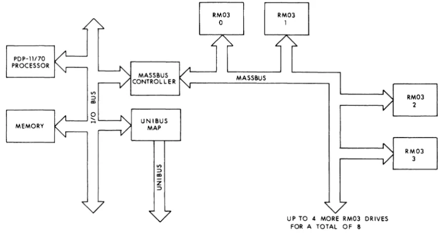
PDP-1l170 PROCESSOR
MEMORY
MASSBUS CONTROLLER
UNIBUS MAP
on
:::>
II)
z
:::>
[image:43.569.63.509.51.289.2]UP TO 4 MORE RM03 DR IVES FOR A TOTAL OF 8
Figure 2-7 RWM03 SYSTEM BLOCK DIAGRAM
RM03 2
RM03 3
o
~
o
~~
I w
(»
I
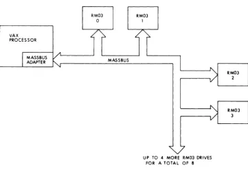
VAX PROCESSOR
RM03
o RM03 1
I I
[image:44.572.119.481.45.299.2]UP TO 4 MORE RM03 DRIVES FOR A TOTAL OF 8
Figure 2-8 REM03/RGM03 SYSTEM BLOCK DIAGRAM
RM03 2
0
Ci5
'"
0
~
RM03 ~
RECORDING METHOD
The RM02/03 utilizes Modified Frequency Modulation (MFM) to read and write data. Data is written on the disk by magnetizing small sec-tions (bit cells) of the oxide on the disk in different direcsec-tions, i.e. either positively or negatively. A change in the direction of magnetization (flux transition) in the clock area of a bit cell indicates whether the bit represented is a 1 or a O.
DATA ORGANIZATION
The RM02/03 disk pack consists of 3 disk platters, each recorded on both sides, enclosed between two outside platters for protection of the pack. Each disk pack contains a total of 6 surfaces: 5 data surfaces for recording and 1 servo surface permanently recorded with information used to position the read/write heads at the specified cylinder. The RM02/03 has 6 heads-5 are read/write heads which correspond to the 5 data surfaces and the additional head is the servo read head, which corresponds to the servo surface. The disk pack is divided into 823 cylinders. Each cylinder is divided into 5 tracks, corresponding to the 5 data surfaces. Each track is divided into 32 sectors with a data storage capacity of 4096 bits (512 bytes). Each sector is divided into a header field and a data field. The header field consists of an 48-bit header that contains the cylinder, track, and sector addresses and a l6-bit header CRC (Cyclic Redundancy Check). The data field con-sists of 4096 bits (512 bytes) of data and a 32-bit data ECC (Error Correction Code). The preamble and the header field can only be written by the utility program that formats these disk packs.
OPERATION
The RJM02 subsystems have 20 registers, the RWM03 subsystems have 22 registers, and the REM03 and RGM03 subsystems have 16 registers plus the MASSBUS adapter registers. (Refer to the register section at the back of this book for register diagrams and bit definitions).
Before a READ or a WRITE operation can begin, the processor loads the bus address, word count, control and status 2, desired cylinder, desired sector/track address, and control and status 1 registers re-spectively.
DISK DRIVES
After the bus address, word count, control and status 2, desired cylin-der, and desired sector/track address registers have been loaded, the control and status 1 register is loaded with the READ or WRITE com-mand from the processor. The comcom-mand is tnen executed. If the heads are not currently positioned at the specified cylinder, the drive will do an implied SEEK, which moves the heads to the correct cylin-der. The read/write heads then read the headers on the specified track to locate the specified sector.
During a READ operation, data bits are read from the disk serially. The controller/adapter assembles the bits into 16-bit parallel words and generates a parity bit for each 16-bit word. The controller/adapter then transfers each 16-bit word plus parity to the specified memory location. This process continues until the proper word count is reached. When the READ operation has been completed, an interrupt is generated to alert the processor that the data has been read off the disk and is stored in the specified memory location.
During a WRITE operation, the controller/adapter reads each 16-bit parallel word from the specified memory location and generates a parity bit for each. The controller/adapter transfers each 16-bit word plus parity to the drive. The drive then serially writes the bits onto the disk. This process continues until the proper word count is reached. When the WRITE operation has been completed, an interrupt is gener-ated to alert the processor that the data has been written onto the disk.
DATA INTEGRITY
Several error checking and correction features of the RM02/03 ensure that the data is correct.
The RM02/03 uses the servo disk surface to position the read/write heads at the specified cylinder. The sector header field is read to verify that it is the specified cylinder, track, and sector. The header CRC is used to ensure that the header field has been read correctly. The header bits are used to generate a second CRC, which is then com-pared to the CRC read from the end of the header field on the disk. If there is a discrepancy between the two CRCs, the controller/adapter alerts the processor by setting a bit in the error 1 register.
To ensure that data is written correctly, a WRITE CHECK command may be issued by the software. This causes the RM02/03 to read the data just written and the controller/adapter to compare it to the data stored in memory.
The ECC (Error Correction Code) logic is used to ensure that the data field has been read correctly. The data bits are used to generate a second ECC, which is then compared to the ECC read from the end of
-40-the data field on -40-the disk. If -40-there is a discrepancy between -40-the two ECCs, the processor uses them to determine which bits are in error and to reconstruct the correct data. One error of up to 11 incorrect bits
In a row can be reconstructed in a sector. The controller/adapter
reports the position of the error to the processor and sends the proc-essor an error burst pattern and an error correction pattern to allow the software to correct the error in memory. If a sector containing more than one error is reported to the procesor by the controll-er/adapter as an incorrectable error, the processor may invoke a suitable error recovery procedure consisting of OFFSET positioning, RECALIBRATION, and REREAD operations.
INTERRUPTS
The RM02/03 disk system controller/adapter uses a vectored inter-rupt to cause the program to branch to an interinter-rupt service routine. An interrupt can occur only if the INTERRUPT ENABLE bit in the control and status 1 register is set. Once the INTERRUPT ENABLE bit is set, an interrupt request is generated whenever either the SPECIAL CON-DITION or READY bit in the control and status 1 register is also set.
When the SPECIAL CONDITION bit is set, it indicates that some error or unusual condition exists and an interrupt is generated to cause the program to branch to an error handling routine. When the READY bit is set, the controller/adapter has successfully completed the opera-tion and is ready to accept a command. An interrupt request is made so that the program can branch to an interrupt service routine.
The interrupt priority level is 5 and the interrupt vector address is 254. Note that the priority level can be changed with a priority plug and the vector address can be changed by jumpers in the interrupt control logic. However, any DIGITAL programs or other software referring to the priority level or interrupt vector address must also be changed if the priority plug or the vector address is changed.
RELIABILITY/MAINT AI NABILITY
Reliability means long life expectancy and uninterrupted processing of the disk system. Special design features of the RM02/03 disk systems provide these qualities of high reliability as well as ease of mainte-nance.
• Modular construction of the RM02/03 enables parts to be quickly removed and replaced during routine servicing and maintenance. • Off-line tester allows the RM02/03 to be serviced independent of the
host processor.
DISK DRIVES
START READY FAULT PROTECT
o
o
o
DODD
FRONT PANEL CONTROLS AND INDICATORSA B
DO
DRIVE CABINET SWITCHES
Figure 2-9 RM02/03 CONTROLS AND INDICATORS
CONTROLS AND INDICATORS
The front panel controls allow the operator to control the disk drive manually and the indicator lights provide drive status information. The A and B swtiches located on the drive cabinet door allow the operator to enable different MASS BUS ports.
-42-• START switch and associated lamp (alternate-action pushbutton and associated red light indicator on front panel)
Depressing this switch causes the START indicator light to come on and the drive to accelerate the disk pack up to speed. Once the disk pack is up to speed, the READY indicator will light. Depressing the switch again causes the drive to stop the disk pack and the START indicator light to go out.
• READY lamp (red light indicator on front panel)
When lit, indicates that the disk pack is up to speed and the drive is ready to execute a command. This lamp will blink during start/stop sequences .
• DRIVE NUMBER receptacle (unlabeled receptacle on front panel)
Each drive comes with eight numbered (0-7) plugs. The drive num-ber is set by inserting one of the numnum-bered plugs into the recepta-cle. If no plug is in the receptacle, the drive cannot be selected by the processor. Note that drive number units cannot be duplicated.
• FAULT CLEAR switch and associated lamp (momentary pushbutton and associated red light indicator on front panel)
Depressing this switch causes the indicator light to go out if the fault condition has been corrected.
When lit, the drive has detected a hardware fault such as write current failure or a dc power supply failure.
• WRITE PROTECT switch and associated lamp (alternate-action pushbutton and associated red light indicator on front panel)
Depressing this switch causes the associated indicator to light and prevents the processor from writing on the disk pack. Depressing this switch again causes the indicator light to go out and enables WRITE operations.
• A and B switches/lamps (alternate-action pushbuttons/red light in-dicators on drive cabinet door)
Depressing the A switch enables MASSBUS port A. Depressing the B switch enables MASSBUS port B. When both switches are de-pressed or when neither switch is dede-pressed, both MASSBUS ports are enabled.
SPECIFICATIONS
MECHANICAL Cabinet
Controller/adapter mounting code
RJM02
RWM03
REM03
RGM03
Height
Width
Depth
Weight
PERFORMANCE
Drives per controller/adapter
Formatted capacity per disk pack
Peak transfer speed
RM02
RM03
Average access time·
RM02
RM03
Average seek time
Average latency (rotational) time
RM02
DISK DRIVES
Freestanding
2SUs
MASSBUS port
Option panel space
MBA slot
39 in (99 em)
21.7 in (55.1 em)
31 in (79 em)
430 Ibs (195 kg)
8
67MB
806 KB/s
1200 KB/s
42.5 ms
38.3 ms
30ms
12.5 ms
RM03
Track-to-track seek
Rotational speed
RM02
RM03
Surfaces per disk pack
Tracks per surface
Sectors per track
Bytes per sector
Tracks per inch
Bits per inch
ELECTRICAL
Starting (surge) current
Surge duration
Drive operating current
Power consumption
Heat dissipation
Drive operating voltage
Phase
Line frequency
Drive receptacles
Line cord length
ENVIRONMENTAL Operating temperature Storage temperature 8.3ms 6ms 2400 rpm 3600 rpm
5 data, 1 servo
823
32 (16-bit format)
512
384
6038
30 A at 120 Vac 22 A at 240 Vac
10-12 s
11 A at 120 Vac 5.3 A at 240 Vac
1050 Watts maximum
4128 Btus/hr maximum
120 Vac +8, -18 240 Vac +17, -27
1-phase
60 Hz +0.6,-1 50 Hz +0.5,-1
NEMA #5-15R (120 Vac), NEMA #6-15R (240 Vac)
6ft
59°F-90°F (15°C-32°C)
DISK DRIVES
Operating relative humidity 20%-80% (non-condensing)
Storage relative humidity 5%-95%
(non-condensing)
Maximum wet bulb temperature 78°F (26°C)
Maximum operating altitude 6500 ft (2000 m) above sea level
-46-~
\. ''',"0 I~~-I"I[
I~III
:
::J
-48-RMBO
The RM80 is a freestanding, random-access, disk storage system which connects to the processor via the MASSBUS adapter (MBA). The REM80 subsystems are supported by VAX-11 1780 systems and the RGM80 subsystems are supported by VAX-11/7S0 systems. The RM80 was designed to operate at very high speeds in high usage environments in a wide range of applications.
FEATURES
• Formatted capacity of 124 MB • Winchester fixed-media technology • Sealed Head Disk Assembly (HDA)
• Internal microprocessor-controlled diagnostics
• Overlapped seeks optimize seek time and provide increased system throughput on multidrive systems
• Static dual-access capability
• Direct Memory Access (DMA) data transfers
• Expandable up to a total of 8 disk drives per subsystem
DESCRIPTION
The REM80-AA(AD) and RGM80-AA(AD) disk storage subsystems consist of a single-access, freestanding RM80 disk drive with non-removable head disk assembly, a MASSBUS adapter (MBA), and a MASSBUS cable. Up to seven more add-on RM80 disk drives (single-or dual-access) may be added to these subsystems.
The REM80-BA(BD) and RGM80-BA(BD) disk storage subsystems consist of a dual-access, freestanding RM80 disk drive with non-re-movable head disk assembly, two MASSBUS adapters (MBAs), and two MASSBUS cables. Up to seven more add-on RM80 disk drives (single- or dual-access) may be added to these subsystems. Note that dynamic (simultaneous access) dual-port capability of disk subsys-tems is not supported by DIGITAL operating system software or diag-nostics. However, the REM80-BA(BD) and RGM80-BA(BD) subsys-tems can be statically shared by two processors or connected to one processor through two MBAs for maximum system availability.
RECORDING METHOD
I c.n o I
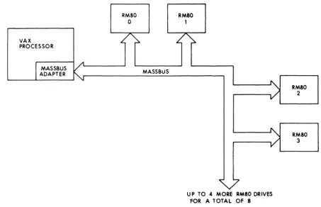
VAX PROCESSOR
I
MASSBUS ADAPTERRM80 0
~
~
MASSBUSRM80 1
A
1\,
V
I
)
UP TO 4 MORE AM80 DRIVES FOR A TOTAL OF 8
Figure 2-10 REM80/RGM80 SYSTEM BLOCK DIAGRAM
RM80
2
RM80 3
I:)
~
g
[image:56.569.56.509.33.324.2]DATA ORGANIZATION
The RM80 head disk assembly consists of 4 disk platters, each record-tld on both sides. Each head disk assembly contains a total of 8 sur-laces: 7 data surfaces for recording and 1 servo surface permanently recorded with information used to position the read/write heads at the specified cylinder. The RM80 has 15 heads-14 are read/write heads (two per data surface) and the additional head is the servo read head, which corresponds to the servo surface. The head disk assembly is divided into 561 cylinders: 559 are used for data and 2 are used for diagnostics. Each cylinder is divided into 14 tracks (two per data sur-lace). Each track is divided into 32 sectors: 31 data sectors and one additional sector used when one of the sectors on that track is bad. Each sector has a data storage capacity of 4096 bits (512 bytes). Each sector is divided into a header field and a data field. The header field consists of a 48-bit header that contains the cylinder, track, and sector addresses and a 16-bit header CRC (Cyclic Redundancy Check). The data field consists of 4096 bits (512 bytes) of data and a 32-bit data ECC (Error Correction Code). The header field can only be written by the utility program that formats these head disk assemblies.
OPERATION
The REM80 and the RGM80 subsystems have sixteen registers plus the MASSBUS adapter registers. (Refer to the register section at the back of this book for register diagrams and bit definitions).
Before a READ or WRITE operation can begin, the processor loads the MBA virtual address, MBA byte counter, desired cylinder, desired sector/track address, and control and status 1 registers respectively.
The MBA virtual address register specifies the starting memory ad-dress of the storage location for the data to be read from or written onto the disk. The MBA byte counter register specifies the total number of bytes to be transfered between the disk and memory. The desired cylinder register and the desired sector/track address register specify the sector of the disk to be read or written.
DISK DRIVES
During a READ operation, data bits serially read from the disk are assembled into 16-bit parallel words and a parity bit is generated for each 16-bit word. Every 16-bit word plus parity is then transferred to the MBA. The MBA combines two 16-bit words into a 32-bit memory word and generates a parity bit for each 32-bit word. Every 32-bit word plus parity is then transferred into the memory location specified. This process continues until the byte count in the MBA virtual address register is reached. When the READ operation is completed, an inter-rupt is set to alert the processor that the data has been read off the disk and stored in the specified memory location.
During a WRITE operation, each 32-bit word of data is read from memory and transferred to the MBA, which divides the 32-bit word into two 16-bit parallel words and generates a parity bit for each 16-bit word. The MBA then transfers the two 16-bit words plus parity to the drive. The drive checks the parity and then serially writes the bits onto the disk one by one. This process continues until the proper word count is reached. When the WRITE operation has been completed, an interrupt is generated to alert the processor that the data has been written onto the disk.
DATA INTEGRITY
Several error checking and correction features of the RM80 ensure that the data is correct.
The RM80 uses the servo disk surface to position the read/write heads at the specified cylinder. The sector header field is read to verify that it is the specified cylinder, track, and sector. The header CRC is used to ensure that the header field has been read correctly. The header bits are used to generate a second CRC, which is then compared to the CRC read from the end of the header field on the disk. If there is a discrepancy between the two CRCs, the MBA alerts the processor by setting a bit in the error 1 register.
To ensure that data is written correctly, a WRITE CHECK command may be issued by the software. This causes the RM80 to read the data just written and the MBA to compare it to the data stored in memory.
The ECC (Error Correction Code) logic is used to ensure that the data field has been read correctly. The data bits are used to generate a second ECC, which is then compared to the ECC read from the end of the data field on the disk. If there is a discrepancy between the two ECCs, the processor uses them to determine which bits are in error and to reconstruct the correct data. One error of up to 11 incorrect bits in a row can be reconstructed in a sector. The MBA reports the posi-tion of the error to the processor and sends the processor an error
-52-burst pattern and an error correction pattern to allow the software to correct the error. If a sector contains more that one error, the MBA ulerts the processor by setting a bit in the error 1 register.
INTERRUPTS
The RM80 disk system MBA uses a vectored interrupt to cause the program to branch to an interrupt service routine. The RM80 gener-ales an interrupt at the completion of an operation, when a error has been detected, or when a drive comes on-line.
RELIABILITY/MAINTAINABILITY
Reliability means long life expectancy and uninterrupted processing of the disk system. Special design features of the RM80 disk systems provide these qualities of high reliability as well as ease of maintenance.
• Hinge-mounted modules for easy access.
• Winchester technology (Sealed Head Disk Assembly) requires no alignment of the heads.
• Modular construction of the RM80 enables parts to be quickly re-moved and replaced during routine servicing and maintenance. • On-line microprocessor-controlled diagnostic capability allows
faults to be quickly isolated and corrected.
I::lEJI2l
~ FAULT ~
WRITE PROT
FRONT PANEL CONTROLS AND INDICATORS