2019 International Conference on Computer Science, Communications and Big Data (CSCBD 2019) ISBN: 978-1-60595-626-8
Three-Dimensional Reconstruction Method with Parameter Optimization
for Point Cloud Based on Kinect v2
Kai-zhang WANG
1, Tong-kai LU
1, Qi-hang YANG
1, Xi-hao FU
1,
Ze-hong LU
1,2,3,4, Bo-lun WANG
1,2,3and Xin JIANG
1,2,3,* 1Key Laboratory of Mathematics, Informatics and Behavioral Semantics and School of Mathematics and Systems Science, Beihang University, Beijing, China
2Peng Cheng Laboratory, Shenzhen, Guangdong, China, 518055 3
Beijing Advanced Innovation Center for Big Data and Brain Computing (BDBC), Beijing, 100191, China
4
School of Mathematical Science, Peking University, Beijing, China
*Corresponding author
Keywords: 3D Reconstruction, Parameter optimization, Kinect v2.
Abstract: Three-Dimensional (3D) reconstruction is a significant part in the field of computer vision. In this paper, we use Kinect v2 to obtain the 3D point cloud. As a consumer used 3D sensor, Kinect has numerous advantages such as low price, relative high dot per inch (DPI) and frames per second (FPS) and strong robustness. During the experiment, the object was placed on a turntable spinning and stop for every 12°, collecting 30 images of point cloud in total. Then we used Iterated Closest Points (ICP) algorithm to calculate the optimal rotation matrix and translation matrix to match all point cloud into the same coordinate. After that, three algorithms including Statistical Outlier Removal, Movement Least Squares (MLS) and Voxelgrid were used to reduce the noise. At last, we applied greedy projection algorithm to generate the triangulate mesh. During the procession, we observed the relationship between parameters and outcome and drew pictures to have the data more visible, which gave out the optimal parameters in return.
Introduction
Three-Dimensional (3D) reconstruction play a vital role in computer vision, which is the basis of numerous fields, including computer-aided geometric design, computer animation, reverse engineering, medical diagnosis, video entertainment and others. In recent years, 3D point cloud reconstruction technology has developed rapidly, including semi-global matching technology like StereoCBinocular Matching [2], Binocular Stereo Vision [3], Structure From Motion technology (SFM) [4], progressive reconstruction technology (or Depth Filtering) like SVO (Fast Semi-Direct Monocular Visual Odometry) [5] or REMODE (Probabilistic, monocular dense reconstruction in real time) [6] and Direct Reconstruction technology [7].
Traditional 3D reconstruction relies heavily on expensive 3D scanning equipment and requires the scanned target to keep still for a period of time. In recent years, the development of large-scale computing power of computer hardware, especially the development of GPU and distributed computing, realize some real-time and efficient solutions. Currently, the mainstream methods are mainly divided into two categories: depth camera-based 3D reconstruction and Image-based 3D reconstruction. Kinect is the representative of the depth camera who has many advantages, including low price, relative high DPI and FPS, and strong robustness.
reconstruction [11]. Qualcomm's open source project kfusion is also aiming to solve relative problems [12]. All above, Kinect 3D reconstruction technology has wide application prospect.
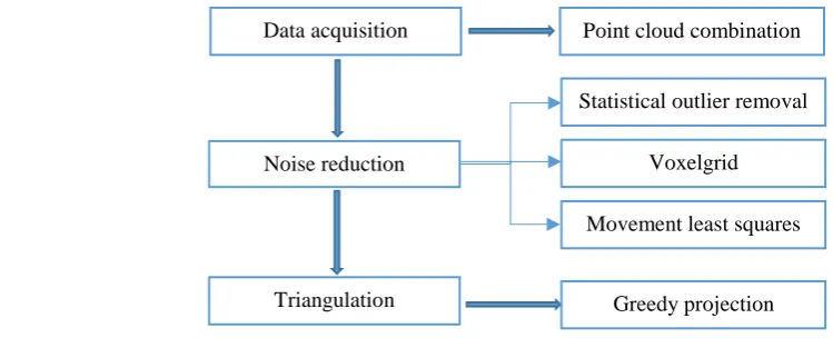
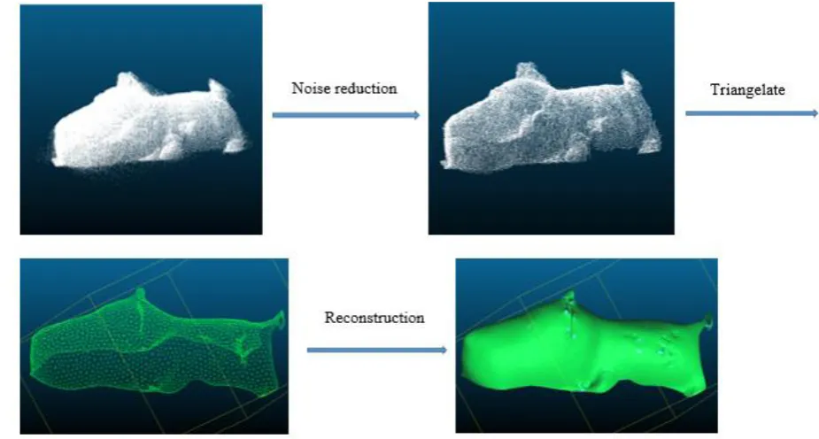
[image:2.595.65.440.166.318.2]The major contribution of this paper are as follows. First, a 3D reconstruction process is realized based on a low-cost sensor, and have an acceptable result. Second, a series of methods are mixed to finish the reduction process, during which the parameters are adjusted to be optimal. Besides, the whole process shows good robustness and have a good value of application.
Figure 1. The general procession of our work.
Data Acquisition
We have a turntable with a remote control and a Kinect v2 sensor which is linked to a computer to receive and save the pictures of point cloud. The object we get is a dog shaped toy. Sitting on the turntable, the object spin and stop every 12° while the computer capturing the point cloud from Kinect, collecting 30 times per round. The suitable distance between Kinect and the object is about 0.5m for the reason that the images will be vague if either too far or close.
Combination
We should tackle with the point cloud images first considering that they are in the different coordinate. In our paper, we decide to use the Iterated Closest Points Algorithm (ICP), which was firstly proposed by Besl PG and Mckay ND in 1987. Based on the optimal least squares principle, the method have gained vastly attention and application.
Suppose that we have too group of point, let P be the measured data point set and X be the targeted data point set, which satisfy two conditions: Firstly, the group P and X have same quantity, which means that Np = Nx. Secondly, every point in P has a corresponding point in X. It is our goal to find the
best rotation matrix R and translation vector 𝑞⃗𝑇for group P. Let 𝑞⃗𝑅 = [𝑞0𝑞1𝑞2𝑞3]𝑡, where 𝑞0 ≥ 0, and 𝑞02 + 𝑞12+ 𝑞22+ 𝑞32 = 1, and 𝑞⃗𝑇 = [𝑞4𝑞5𝑞6]𝑡.The mean square objective function to be minimized is
𝑓(𝑞⃗) =𝑁1
𝑝∑ ‖
𝑁𝑝
𝑖=1 𝑥⃗𝑖− 𝑅(𝑞⃗𝑅)𝑝⃗𝑖 − 𝑞⃗𝑇‖2. (1)
The center of mass 𝜇⃗𝑝 of the point cloud 𝑃 and the center of mass 𝜇⃗𝑥 for the point cloud X are given by
𝜇⃗𝑝 =𝑁1
𝑝∑ 𝑝⃗𝑖
𝑁𝑝
𝑖=1 and 𝜇⃗𝑥 = 1
𝑁𝑥∑ 𝑥⃗
𝑁𝑥
𝑖=1 . (2)
The cross-covariance matrix 𝛴𝑝𝑥 of the group P and 𝑋 is given by Data acquisition
Noise reduction
Triangulation
Point cloud combination
Statistical outlier removal
Voxelgrid
Movement least squares
𝛴𝑝𝑥 =𝑁1
𝑝∑ [
𝑁𝑝
𝑖=1 (𝑝⃗𝑖 − 𝜇⃗𝑝)(𝑥⃗𝑖− 𝜇⃗𝑥)𝑡] = 1 𝑁𝑝∑ [
𝑁𝑝
𝑖=1 𝑝⃗𝑖𝑥⃗𝑖𝑡] − 𝜇⃗𝑝𝜇⃗𝑥𝑡. (3)
The column vector 𝛥 =[𝐴23 𝐴31 𝐴12]𝑇 where 𝐴𝑖𝑗 =(𝛴𝑝𝑥− 𝛴𝑝𝑥𝑇 )𝑖𝑗. This vector is used to form the symmetric 4 × 4 matrix 𝑄(𝛴𝑝𝑥)
𝑄(𝛴𝑝𝑥) = [
𝑡𝑟(𝛴𝑝𝑥) △ 𝑇 △ 𝛴𝑝𝑥+ 𝛴𝑝𝑥𝑇 − 𝑡𝑟(𝛴
𝑝𝑥)𝐼3
]. (4)
I3 is the 3 × 3 identity matrix. The unit eigenvector 𝑞⃗𝑅 = [𝑞0 𝑞1 𝑞2 𝑞3]𝑡 is corresponding to the
maximum eigenvalue of the matrix 𝑄(𝛴𝑝𝑥). Then we have the rotation matrix
R = [ 𝑞02+ 𝑞
12− 𝑞22− 𝑞32 2(𝑞1𝑞2− 𝑞0𝑞3) 2(𝑞1𝑞3+ 𝑞0𝑞2) 2(𝑞1𝑞2+ 𝑞0𝑞3) 𝑞02+ 𝑞
22− 𝑞12 − 𝑞32 2(𝑞2𝑞3− 𝑞0𝑞1) 2(𝑞1𝑞3− 𝑞0𝑞2) 2(𝑞2𝑞3+ 𝑞0𝑞1) 𝑞02+ 𝑞32 − 𝑞12− 𝑞22
] . (5)
The optimal translation vector is given by
𝑞⃗𝑇 = 𝜇⃗𝑥− 𝑅( 𝑞⃗𝑅) 𝜇⃗𝑝. (6)
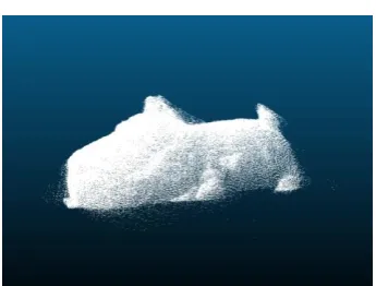
[image:3.595.211.384.310.441.2]The result shows as below.
Figure 2. The combined point cloud scanned by Kinect.
Point Cloud Processing
Noise Reduction
After the point cloud has been reverting to the same coordinate, further procession like noise reduction and triangulation could be done. In this part, we will introduce three mixed algorithms as they work together to finish the noise reduction. Meantime, the parameters in those algorithms will be optimize.
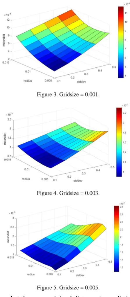
To figure out the optimal parameter, we take a point cloud of bunny from Stanford for example. We add some random noise which follow the distribution of N(0,1) as our experimental group. In order to estimate the result of noise reduction, we use k-d tree to traverse all the points in bunny and take down the maximal minimal distance and the mean minimal distance of the denoising point cloud. The parameters are initiated as num = 10, stddev = 0.1~0.5(jump by 0.1), gridsize = 0.001~0.005(jump by 0.002), radius = 0.005~0.014(jump by 0.001) and the outcomes are followed:
Figure 3. Gridsize = 0.001.
[image:4.595.180.404.156.666.2]Figure 4. Gridsize = 0.003.
Figure 5. Gridsize = 0.005.
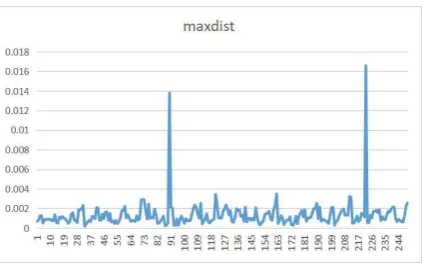
Figure 6. The change of maximal minimal distance.
The figure show us that the change of maximal minimal distance (maxdist) is quiet random.
Improvement
[image:5.595.183.406.301.436.2]Some isolate point is remained after the MLS reduction, so we add another Statistical Outlier Removal after the MLS while fixing the gridsize at 0.003, num = 20 and stddev = 2.
[image:5.595.208.390.451.615.2]Figure 7. Meandist after improvement.
Figure 8. Maxdist after improvement.
The maxdist still distribute randomly and meandist follow the same trend as before. The minimal value of meandist is about 0.006 when radius = 0.005 and stddev = 0.06.
Figure 9. The general procession of noise reduction.
Conclusion
In the paper we propose a way to acquire the point cloud based on Kinect. We use the ICP algorithm to calculate the best rotation matrix and translation matrix to have all the point cloud into the same coordinate. Then a series algorithm of noise reduction are proposed, including the statistical outlier removal, voxelgrid and movement least squares. At first, we try 250 group of data to optimal the parameter. Afterwards, we find that some isolate point still remained so another statistical outlier removal is added to the last MLS. This time we have a good result and calculate the minimal value of meandist is about 0.006.
Acknowledgement
This work is supported by National Key Research and Development Program of China (Grants No. 2018YFB1107402, No. 2017YFB0701702.) and NSFC (Grants No. 11290141, No. 11571028).
References
[1] Hirschmüller H. Accurate and efficient stereo processing by semi-global matching and mutual information[C]//null. IEEE, 2005: 807-814.
[2] Hirschmuller H. Stereo processing by semi-global matching and mutual information [J]. IEEE Transactions on pattern analysis and machine intelligence, 2008, 30(2): 328-341.
[3] Moreau J, Ambellouis S, Ruichek Y. 3D reconstruction of urban environments based on fisheye stereovision[C]//2012 Eighth International Conference on Signal Image Technology and Internet Based Systems. IEEE, 2012: 36-41.
[4] Koenderink J J, Van Doorn A J. Affine structure from motion [J]. JOSA A, 1991, 8(2): 377-385.
[6] V. Usenko, J. Engel, J. Stuckler, and D. Cremers. Reconstructing Street-Scenes in Real-Time From a Driving Car.
[7] Ra´ul Mur-Artal and Juan D. Tard´os Probabilistic Semi-Dense Mapping from Highly Accurate Feature-Based Monocular SLAM, 2015.
[8] Vollmer, J. and Mencl, R. and Mueller, H. Improved Laplacian smoothing of noisy surface meshes [J].Wiley Online Library, 1999, 10.
[9] Newcombe R A, Izadi S, Hilliges O, et al. Kinect Fusion: Real-time dense surface mapping and tracking[C]//2011 IEEE International Symposium on Mixed and Augmented Reality. IEEE, 2011: 127-136.
[10] Izadi S, Kim D, Hilliges O, et al. Kinect Fusion: real-time 3D reconstruction and interaction using a moving depth camera[C]//Proceedings of the 24th annual ACM symposium on User interface software and technology. ACM, 2011: 559-568.
[11] Pirovano M. Kinfu–an open source implementation of Kinect Fusion+ case study: implementing a 3D scanner with PCL [J]. Project Assignment, 2012.
[12] Whelan T, Kaess M, Fallon M, et al. Kintinuous: Spatially extended kinectfusion [J]. 2012.
[13] Xia L, Chen C C, Aggarwal J K . Human detection using depth information by Kinect[C]// CVPR 2011 WORKSHOPS. IEEE, 2011.
[14] Khoshelham K, Elberink S O. Accuracy and resolution of kinect depth data for indoor mapping applications [J]. Sensors, 2012, 12(2): 1437-1454.
[15] Xia L, Chen C C, Aggarwal J K. Human detection using depth information by Kinect[C]// Computer Vision & Pattern Recognition Workshops. 2011.
[16] Biswas K K, Basu S K. Gesture recognition using microsoft kinect®[C]//The 5th international conference on automation, robotics and applications. IEEE, 2011: 100-103.
[17] Chang Y J, Chen S F, Huang J D. A Kinect-based system for physical rehabilitation: A pilot study for young adults with motor disabilities[J]. Research in developmental disabilities, 2011, 32(6): 2566-2570.
[18] Yang Hu 1, Le Wang 1, Lirong Xiang 1, Qian Wu 1 and Huanyu Jiang, Automatic Non-Destructive Growth Measurement of Leafy Vegetables Based on Kinect, Sensors 2018, 18, 806.