2019 2nd International Conference on Informatics, Control and Automation (ICA 2019) ISBN: 978-1-60595-637-4
Research and Application of Sensor Detection Technology for UHF
Partial Discharge Tester
Guang-ke XU
*, Ling-ying CHEN, Wei-wei ZHANG, Xing LI,
Yu-xin YUN and Fu-chun SUN
State Grid Shandong Electric Power Research Institute, Jinan, 250002, China
*Corresponding author
Keywords: Sensor detection technology, UHF partial discharge tester, Sensitivity, Equivalent altitude.
Abstract. UHF partial discharge tester can detect the hidden insulation problems and locate the defects as early as possible. At present, there are more and more manufacturers and kinds of species, and product quality is difficult to guarantee. The application unit is not able to effectively test the UHF partial discharge tester, and the accuracy of test data cannot be guaranteed. The faulty tester may cause missed or wrong test and cause immeasurable loss to the power system. Based on the reality, this paper studies the detection technology of UHF sensor, and applies it in the laboratory to effectively trace the source of the sensor to ensure the accuracy of the data of the tester.
Introduction
With the development of power industry in China, the requirements for power quality and reliability are increasingly highly. GIS with its advantages of compact structure and high reliability, has been widely used in power system. However, due to its complex structure, it is difficult to judge and eliminate insulation faults once they occur. Partial discharge is not only the symptom and manifestation of insulation degradation, but also the cause of further insulation degradation. Therefore, partial discharge detection in GIS can detect early insulation defects and avoid their development, which is very important for the safe operation of GIS [1].
In the early 1980s, the British central electricity authority laboratory proposed the UHF partial discharge test technology. Partial discharge pulse time is very short (nanoseconds), so the frequency range of discharge signal generated by the included is from dc to several GHz. However, the common interference signal frequency is below 500 MHz, so the UHF method has less interference and can realize fault location and insulation defect pattern recognition. It has been widely used in the current GIS partial discharge detection. The research work of Strathclyde university in the UK, Stuttgart university in Germany, Delft university in the Netherlands and Nagoya university in Japan is the most outstanding. The research on UHF detection in China started late, but at present, Chongqing university [2] and Xi'an jiaotong university have made some progress.
However, there is no perfect sensor detection method for UHF partial discharge tester, which cannot guarantee the accuracy of measurement data and is difficult to effectively evaluate the state of GIS.In this paper, the detection technology of UHF sensor is studied based on the reality, and it is applied in the laboratory to trace the source of the sensor effectively.
Testing Principle of Partial Discharge Tester
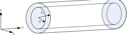
GIS can be seen as a waveguide system with two coaxial conductors according to its construction (shown in Fig. 1). The inner conductor is HV conductor and the outer conductor is the metal shell. The electric potential of the outer conductor is zero. The space between the two conductors is filled with SF6. The dielectric constant of SF6 is ε, and the magnetic permeability is μ.
H j E E j H
(1)
0 0 E H (2)
Solve the equations and (3) can be worked out as following.
0 0 2 2 2 2 H k H E k E (3)
Where, k and it is the phase constant.
The electromagnetic waves radiated by PD in GIS consist of transverse electromagnetic waves (TEM), transverse electric waves (TE) and transverse magnetic waves (TM).
TEM is a non-dispersive wave. It has no cut-off frequencies and can pass through the waveguide with all the frequencies. TE and TM are dispersive waves and they have respective cut-off frequencies. Therefore, the TE and TM waves can pass through the waveguide only when their frequencies are larger than the cut-off frequencies.
a b
x y
[image:2.595.194.405.317.378.2]z
Figure 1. Coaxial waveguide structure.
The edge conditions of TEM are that when r=a, φ=u, and when r=b, φ=0. Thus, transmitted field quantity along Z axis can beworked out in (4) and (5).
) ( ) ln( kz t j r e a b r u
E (4)
0
Z E
H r
(5)
In the equations, u is the signal amplitude, ω is the signal angular frequency, and Z0 is the wave impedance.
In a single waveguide, the electromagnetic field equations of TE and TM waves can be solved as following. ) ( 1 2
z z
c r H r r E k j
E (6)
) ( 1 2 r H E r k j
E z z
c
(7)
) ( 1 2 r H E r k j
H z z
c r
(8)
)
z z
c H r r E k j
H 12( (9)
Where 2k2kc2, and β is the propagation constant. kcmeansthe phase constant according to the cut-off wavelength.
When Ez=0, Hz≠0, the electric field of TE has only the transverse component. Therefore Hz can be
) (
} sin cos )]{ ( ) (
[ n c n c j t z
z e
n n r k BN r k AJ
H
(10)
When Hz =0, Ez≠0, the magnetic field of TM has only the transverse component. Therefore Ez can
be solved in (11).
) ( } sin cos )]{ ( ) (
[ j t z
c n c n
z e
n n r k DN r k CJ
E
(11)
Where, Jn (kcr) and Nn (kcr) are the Bessel function of the first kind and second kind respectively. A,
B, C and D are all the constants.
When the wave frequency is high enough, k>kc, and β is a real number. Then e -jβz
is the propagation factor and the electromagnetic waves propagate along the Z axis.
When the wave frequency is smaller, k<kc, and β is an imaginary number. Then e|β|z is the
attenuation factor and the electromagnetic waves attenuate quickly along the Z axis.
Detection Device and Method
Principle of UHF Sensor Detection
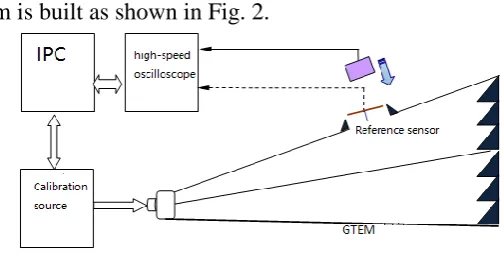
[image:3.595.161.413.315.445.2]The detection platform is built as shown in Fig. 2.
Figure 2. The detection platform. Equivalent Height Detection
The calibration source injected a calibration pulse signal with a voltage amplitude of 20V into the GTEM chamber, and established a pulse electromagnetic field covering 300M~1500MHz frequency band in the GTEM chamber. The reference sensor is placed at the GTEM chamber opening, and the voltage response VMr of the reference sensor was obtained through the measurement system.[5][6]
The voltage response VMs of the sensor under test are obtained by placing the sensor in a GTEM
chamber with an open hole. The effective height of the sensor under test can be calculated according
to Hsens=(VMs/VMr)*Href, using the known reference sensor Href. Then the average effective height of the
sensor under test is calculated within 300M~1500MHz frequency band. Detection Sensitivity Test
The reference sensor is placed at the opening of the GTEM chamber, and the output voltage amplitude Vi of the calibration source is continuously adjusted from 0V to 1V within the output range of 0 ~ 100V of the calibration source. The voltage response VMr of the reference sensor under the
output voltage amplitude of the calibration source is obtained. According to Ei=VMr/Href, the electric
field intensity Eiat the opening of GTEM cell under the output voltage amplitude of source was
calculated and calibrated. Converse Ei to time domain Ei(t) and pick the maximum value Eitmax on the
curve Ei(t). Draw the corresponding relation curve between the amplitude Vi of the calibrated source
output voltage and the Eitmax of the time domain maximum electric field intensity at the GTEM cell
opening.
maximum time domain electric field Eitmax1intensity corresponding to the calibration source output
voltage amplitude Vi1 is obtained. Eitmax1 is the detection sensitivity of the detector.
Dynamic Range Test
Place the sensor under test at the opening of GTEM chamber, connect the sensor under test with the detector, and adjust the output voltage amplitude of the calibration source to make the detector reach its full range. Record the output voltage amplitude of the calibration source at this time Vi2. The
corresponding curve of the time domain maximum electric field intensity Eitmax at the hole opening of
GTEM chamber with the calibrated source output voltage amplitude Vi is used to obtain Eitmax2. The
electric field intensity is the maximum measurable transient field intensityEitmax2.
According to F=Eitmax2/Eitmin1 calculate the multiple relationship between the maximum
measurable transient electric field intensity and the device sensitivity, and F is dynamic range.
Detecting Devices
Calibration Source
The range of output amplitude is recommended to be from 0 to 100V, with adjustable amplitude function. If the output amplitude is less than the recommended value, the rising time should be reduced to meet the need of dynamic range test. The output waveform is square wave or double exponential pulse. Pulse rising edge is (20%~80%)≤300ps and the half-wave time is within the range of 4ns ~ 100ns.
High-speed Oscilloscope
Analog bandwidth is no less than 2GHz and sampling rate is no less than 10GS/s. GTEM Cell
The frequency domain is 0~2GHz, input impedance is 50Ω±2Ω, and voltage standing wave ratio is ≤1.5.
Unipolar Probe Reference Sensor
The recommended dimensions for a unipolar probe are: radius r=0.65mm, height h=25mm. The monopole probe shall be calibrated by the metrological verification institution.
Laboratory Validation Results
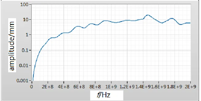
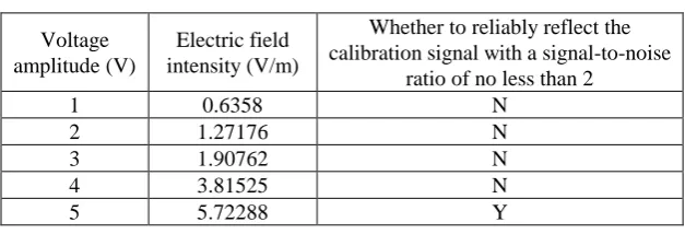
[image:4.595.133.464.555.722.2]An UHF partial discharge tester was randomly selected and tested in the laboratory using the above method. The equivalent height is detected 8.231mm, as shown in Fig. 3 and sensitivity test records are shown in Table 1. It can be seen the basic technical parameters of the tester can be mastered through testing to ensure the accuracy and reliability of the measurement.
Table 1. Sensitivity test record sheet. Voltage
amplitude (V)
Electric field intensity (V/m)
Whether to reliably reflect the calibration signal with a signal-to-noise
ratio of no less than 2
1 0.6358 N
2 1.27176 N
3 1.90762 N
4 3.81525 N
5 5.72288 Y
Summary
In this paper, the detection technology of UHF partial discharge tester is studied and verified in the laboratory from three aspects including equivalent height, sensitivity and dynamic range by using GTEM chamber. Through experiments, it is found that this method can basically master the performance parameters of the tester, which provides strong support for ensuring the accuracy and reliability of field measurement data and ensuring the safe and stable operation of the power grid.
References
[1] Y. Cheng, X. Xie, Y. Chen, X. Hu and Z. Zhu: Study on fractal characteristics of ultra-wideband partial discharge in gas-insulated system with typical defects, Proceedings of the CSEE, Vol. 20, pp. 99-102, 2004.
[2] C. Qiu and N. Wang: Electrical equipment partial discharge and testing techniques, Beijing: Machinery Industry Press, 1994.
[3] X. Li, C. Li, Y. Li, W. Wang and H. Li: Analysis on partial discharge in GIS by FDTD method, Proceedings of the CSEE, Vol. 25, pp. 150-155, 2005.
[4] C. Feng and X. Ma: Introduction to Engineering Electromagnetic Fields, Beijing: Higher Education Press, 2000.
[5] Y. Cheng, X. Xie, Y. Chen, X. Hu and Z. Zhu: Study on fractal characteristics of ultra-wideband partial discharge in gas-insulated system with typical defects, Proceedings of the CSEE, Vol. 20, pp. 99-102, 2004.