2019 International Conference on Artificial Intelligence, Control and Automation Engineering (AICAE 2019) ISBN: 978-1-60595-643-5
Vector Control Method for Induction Motor of Electric Vehicle under the
Constraint of Battery Output Power
Wei ZHANG, Zhan-feng YING
*and Xu-dong ZHANG
School of Energy and Power Engineering, Nanjing University of Science and Technology, Nanjing, China
*Corresponding author
Keywords: Electric vehicle, Induction motor, Vector control, Battery voltage.
Abstract. Vector control is a most widely used control method for induction motor (IM) of electric vehicle (EV). However, the EV battery voltage will rapidly drop to the under-voltage protection point, if the IM torque is output without any limited, especially when the EV battery level is insufficient. As a result, the under-voltage protection of IM driving system would be trigger in advance and the EV endurance will be seriously affected. To address this issue, a vector control method for EV under the constraint of battery output power is proposed. Based on the traditional vector control strategy, this method introduces the closed-loop control of battery output power and combines the power limit curve associated with motor speed and battery voltage to constrain the battery output power. The experimental results show that the proposed vector control method can effectively prevent premature under-voltage protection caused by excessive battery output current, and is helpful to improve the endurance of electric vehicles.
Introduction
In recent years, with the aggravation of energy crisis and environmental pollution, the electric vehicle industry has developed vigorously [1]. IM has become one of the most widely used driving motors of EV, especially for low-speed EV. It is of great significance to study the drive control method of IM for improving vehicle operation performance.
The most widely used algorithm in IM is magnetic field-oriented control (FOC). The core idea of FOC is to decompose the stator current into torque current and excitation current components that can be independently controlled by the means of coordinate transformation. As a result, the IM can obtain good dynamic characteristics that similar to the DC motor [2-4]. In order to further improve the control performance, the IM vector control method is being improved. As found in [5], an indirect vector control method of IM based on parameter online correction is proposed, which improved the torque control performance of the motor. The authors [6] apply single-neuron control to the IM vector control system, which improves the vector control performance of the IM and has strong adaptability and robustness.
The Proposed Vector Control Method
Ideal IM Model
The stator and rotor voltage equations of IM in synchronous rotating dp reference frame are shown in Equation (1).
1
0
0
sd
sd s sd e sq
sq
sq s sq e sd
r r rd
r rq s r d
u R i
dt d
u R i
dt d R i dt R i
. (1)
where symbols u, i, andR denote voltage, current, flux and resistance, subscripts s and r mean stator and rotor, d and q represent axes of rotating reference frame respectively, and e and s1 are
synchronous speed and slip speed, respectively.
In rotor flux orientation reference frame, rd is r and rqis zero. Therefore, the stator and rotor
flux equations are (2).
0
sd s sd m rd
sq s sq m rq
r m sd r rd
m sq r rq
L i L i
L i L i
L i L i
L i L i
. (2)
where Lm,LsandLr are mutual inductance, stator self-inductance and rotor self-inductance.
Combining (1) and (2), the slip speed s1 can be obtained as Equation (3).
1 m sq s r r L i T
. (3)
where Tr Lr /Rr is the rotor time constant, and isq is torque current.
The synchronous speed e is sum of rotor angular speed r and slip speeds1, which is
1
e r s
. (4) The electromagnetic torque Te of IM is calculated by3 2
m
e p sq r
r L
T n i
L
. (5)
where np is the number of pole pairs.
Torque Control Algorithm of EV
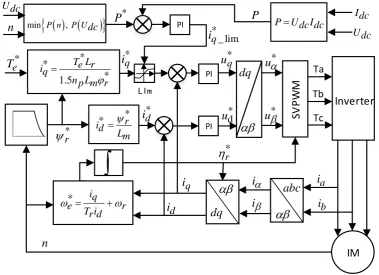
The proposed vector control algorithm for IM of EV is shown in Fig.1, where reference currents * q i
and * d
i are calculated from (2) and (3), and reference rotor flux angle * r
is the integration of * e
algorithm. The proposed vector control method introduces the closed-loop control of battery output power, where Pis the feedback value of the battery output power, which is obtained by multiplying the battery voltage Udc and battery currentIdc, and
*
P is the reference value of the battery output
power, which is obtained by the battery output power limit curve. The closed-loop control result of the battery output power is used to correct the limiting value of the reference torque current *
q
i , which
means that the motor output torque is limited by the battery output power limit curve. Under the closed-loop effect, the battery output power can be well restrained and will not be affected by the change of motor parameters or motor specifications.
PI SV P W M IM Ta Tb Tc * q i * d i
*rq i d i dq abc i i a i b i n dq PI * q u * d u * u * u * iq e r
T ir d
* *
* 1.5
T Le r iq
n Lp m r
Idc Udc LIm Udc n P * P PI * _ lim q i
PUdc dcI
* * r id Lm * r * e T Inverter
[image:3.595.109.489.197.472.2]min P n , P Udc
Figure 1. Vector control method for IM of EV under power constraint.
In practical engineering, the limit curve of battery output power can be obtained from the battery type and output characteristics. The battery output powers limit functionP n
and P U
dc can beexpressed as: 1 1 ( ) 0 Max s s Max Max
P n n
P n k n b n n n
n n
. (6)
Min
2 2 Min
0
( )
dc
dc dc s
Max dc s
U U
P U k U b U n U
P U U
. (7)
where PMax is maximum allowable output power, k1,b1,k2 and b2 are defined as:
1 Max/ Max s
k P n n . (8)
2 Max 2000 / s min
k P U U . (9)
1 2 Max s Max Max / s Max
2 2000 s Max min / s min
b U P U U U . (11) To ensure the effective limitation of battery output power, at a certain moment, the reference value of closed loop of battery output power *
P is defined as:
*
min , dc
P P n P U . (12)
Experimental Results
[image:4.595.178.421.329.443.2]To assess the performance of the proposed vector control method, experimental tests were carried out to verify the control quality, and the test bench is made up of an induction motor, a motor driver, a motor operation monitoring system, a DC stabilized power supply, and an electric eddy-current power tester. The machine specification is given in Table 1, and the motor driver is used to drive and control the experimental motor. The motor operation monitoring system is used to monitor the motor speed, torque, output power, battery voltage, bus current, output power and other related parameters of the driving system, and DC stabilized power supply is used to simulate the battery of EV to power the driving system.
Table 1. Parameters of IM.
Quantity Value
Rated voltage (V) 51
Rated power (kW) 4
Rated speed (r/min) 3000
Number of pole-pairs (P) 2
Stator resistance (mΩ) 20
Rotor resistance (mΩ) 20
Mutual inductance (mH) 1.2
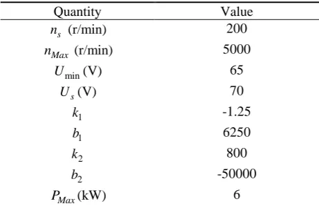
To highlight the advantages of the vector control method proposed in this paper, it is assumed that the EV operates at the following conditions. First, the torque demand *
e
T corresponding to the throttle opening is always kept at the maximum value, assumed that EV operate at the full of throttle. Secondly, the remaining battery level has been insufficient, and the battery voltage is easy to drop during the running of motor operation. The values of related parameters in the power limit curve are given in Table 2. During experiments, the initial voltage of the DC stabilized power supply is set at 72V, and the system under-voltage protection point is set at 65V. By adjusting the output voltage of the stabilized power supply, the running condition under the insufficient battery level state can be simulated. The load excitation value of the eddy current dynamometer is set at 400, the reference value of the torque current *
q
i is set at 380A, and the excitation current * d
i is set at 35A, and the
experimental results are shown in Fig. 2.
Table 2. Parameters of power limit curve.
Quantity Value
s
n (r/min) 200
Max
n (r/min) 5000
min
U (V) 65
s
U (V) 70
1
k -1.25
1
b 6250
2
k 800
2
b -50000
Max
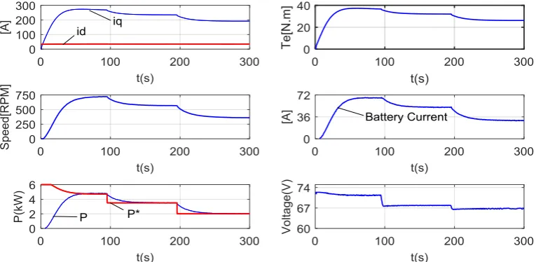
[image:4.595.182.413.630.779.2]Figure 2. Experimental results with the constraint of the battery output power.
As can be seen from the Fig2, at the first 95s, the battery output power limited by the motor speed state is verified. The value of the battery output power referenceP* is calculated from (6), (7) and
(12). As seen in the curve of *
P , the reference output power of the battery decreases with the increase
of the speed. Due to the closed-loop constraint of the battery output power, the battery output powerP is limited to the reference output power *
P , and the torque currentiq, motor torqueTe,
speedn, battery output currentIdc and battery output powerP are gradually stabilize. As shown in the
curves at 95-300s, the battery output power constrained by the battery voltage state is verified, and voltage drop is simulated by adjusting the output voltage of DC stabilized power supply. As seen in the curves, due to the drop of battery voltageUdc, the reference value of battery output power
*
P is
immediately reduced. The torque currentiq, motor torqueTe, speednand battery output currentIdc are
further reduced with the reduction of battery output power P .Figures show good dynamic performance between reference value of battery output power and battery output power. The experimental results effectively verify that the proposed method can quickly and accurately set a reasonable reference value of battery output power according to the motor speed and battery voltage state and constrain the battery output power, which is helpful to improve endurance of EV.
Conclusion
This paper proposes a vector control method for EV under the constraint of battery output power. Based on the traditional vector control strategy, this method introduces the closed-loop control of battery output power and combines the power limit curve associated with motor speed and battery voltage to constrain the battery output power. The experimental results show that the proposed method can effectively improve the endurance of EV.
Acknowledgement
This research was financially supported by the National Science Foundation (51607091).
References
[1] Ouyang Minggao. Development strategy and countermeasures of energy saving and new energy vehicles in China [J]. Automotive engineering, 2006, 28(4):317-321.
[3] Wang Chunming, Ji Yanju, Luan Hui, et al. MATLAB/SIMULINK PMSM vector control system simulation [J]. Journal of jilin university (information science edition), 2009, 27(1).
[4] Sun Danan, Liu Zhigang, Diao Lijun, et al. Accurate directional real-time correction strategy for rotor magnetic field controlled by traction motor vector [J]. Journal of electrotechnics, 2011, 26(9): 116-123.
[5] Zhang Jie, Chai Jianyun, Sun Xudong, et al. Indirect vector control of asynchronous motor of electric vehicle based on parameter online correction [J]. Journal of electrotechnics, 2014, 29(7):90-96.